HMC439QS16G / 439QS16GE
v02.0705
HBT DIGITAL PHASE-FREQUENCY
DETECTOR, 10 - 1300 MHz
FREQUENCY DIVIDERS & DETECTORS - SMT
6
Typical Applications
Features
This Phase Frequency Detector is a key component
in low phase noise frequency synthesis applications
such as:
• Point-to-Point Radios
Ultra Low SSB Phase Noise Floor:
-153 dBc/Hz @ 10 kHz offset @ 100 MHz
Input up to 1300 MHz Fin.
• Satellite Communication Systems
Open Collector Output Buffer Amplifiers
• Military Applications
QSOP16G SMT Package: 29.4 mm2
Differential Input/Single Ended Output
• Sonet Clock Generation
Functional Diagram
General Description
The HMC439QS16G & HMC439QS16GE are digital
phase-frequency detectors intended for use in low
noise phase-locked loop applications for inputs from
10 to 1300 MHz. Its combination of high frequency
of operation along with its ultra low phase noise
floor make possible synthesizers with wide loop
bandwidth and low N resulting in fast switching and
very low phase noise. When used in conjunction with
a differential loop amplifier, the HMC439QS16G &
HMC439QS16GE generate output voltages that can
be used to phase lock a VCO to a reference oscillator.
The device is packaged in a low cost, surface mount
16 lead QSOP package with an exposed base for
improved RF and thermal performance.
Electrical Specifi cations, TA = +25° C, Vcc= 5V
Parameter
Conditions
Maximum Input Frequency
Minimum Input Frequency
Input Power Range
@ 10 kHz Offset
with 100 MHz Input & Pin= 0 dBm
Supply Current (Icc)
6 - 96
Typ.
Max.
Units
MHz
Sine Wave Input
Fin= 10 to 1300 MHz
Output Voltage
SSB Phase Noise
Min.
1300
-10
10
MHz
+10
dBm
2000
mV,
Pk - Pk
-153
dBc/Hz
96
mA
For price,
delivery,
and to placeCorporation:
orders: Analog Devices, Inc.,
For price, delivery, and to place orders, please contact
Hittite
Microwave
One Technology Way, P.O. Box 9106, Norwood, MA 02062-9106
20 Alpha Road, Chelmsford, MA 01824 Phone: Phone:
978-250-3343
978-250-3373
781-329-4700Fax:
• Order
online at www.analog.com
Application Support: Phone: 1-800-ANALOG-D
Order On-line at www.hittite.com
Information furnished by Analog Devices is believed to be accurate and reliable. However, no
responsibility is assumed by Analog Devices for its use, nor for any infringements of patents or other
rights of third parties that may result from its use. Specifications subject to change without notice. No
license is granted by implication or otherwise under any patent or patent rights of Analog Devices.
Trademarks and registered trademarks are the property of their respective owners.
�HMC439QS16G / 439QS16GE
v02.0705
HBT DIGITAL PHASE-FREQUENCY
DETECTOR, 10 - 1300 MHz
0.8
0.8
0.4
0
-0.4
250MHz
800MHz
1.3GHz
0.4
0
-0.4
Vcc=4.75V
Vcc=5.0V
Vcc=5.25V
-0.8
-1.2
FREQUENCY DIVIDERS & DETECTORS - SMT
1.2
ERROR VOLTAGE (Vdc)
ERROR VOLTAGE (Vdc)
1.2
-0.8
6
Error Voltage vs. Supply Voltage,
Pin= 0 dBm, Fin= 250 MHz*
Error Voltage vs. Frequency, Pin= 0 dBm*
-1.2
-p
-p/2
0
p/2
p
-p
-p/2
PHASE DIFFERENCE (rad)
0
p/2
p
PHASE DIFFERENCE (rad)
Error Voltage vs. Temperature,
Pin= 0 dBm, Fin= 250 MHz*
ERROR VOLTAGE (Vdc)
1.2
0.8
0.4
0
-0.4
+25 C
+85 C
-40 C
-0.8
-1.2
-p
-p/2
0
p/2
p
PHASE DIFFERENCE (rad)
SSB Phase Noise Performance,
Pin= 0 dBm, Fin= 100 MHz
0
0
-30
-30
SSB PHASE NOISE (dBc/Hz)
SSB PHASE NOISE (dBc/Hz)
SSB Phase Noise Performance,
Pin= 0 dBm, T= 25 °C
-60
-90
-120
1280 MHz
-150
-180
2
10
3
10
4
10
5
10
6
10
OFFSET FREQUENCY (Hz)
-60
+25C
+85C
-40C
-90
-120
-150
-180
2
10
3
10
4
10
5
10
6
10
OFFSET FREQUENCY (Hz)
* See Gain & Error Voltage Test Circuit herein.
For price,
delivery,
and to placeCorporation:
orders: Analog Devices, Inc.,
For price, delivery, and to place orders, please contact
Hittite
Microwave
One Technology Way, P.O. Box 9106, Norwood, MA 02062-9106
20 Alpha Road, Chelmsford, MA 01824 Phone: Phone:
978-250-3343
978-250-3373
781-329-4700Fax:
• Order
online at www.analog.com
Application Support: Phone: 1-800-ANALOG-D
Order On-line at www.hittite.com
Information furnished by Analog Devices is believed to be accurate and reliable. However, no
responsibility is assumed by Analog Devices for its use, nor for any infringements of patents or other
rights of third parties that may result from its use. Specifications subject to change without notice. No
license is granted by implication or otherwise under any patent or patent rights of Analog Devices.
Trademarks and registered trademarks are the property of their respective owners.
6 - 97
�HMC439QS16G / 439QS16GE
v02.0705
HBT DIGITAL PHASE-FREQUENCY
DETECTOR, 10 - 1300 MHz
FREQUENCY DIVIDERS & DETECTORS - SMT
6
Absolute Maximum Ratings
RF Input (Vcc= +5V)
+13 dBm
Supply Voltage (Vcc)
+5.5V
Channel Temperature (Tc)
135 °C
Continuous Pdiss (T = 85 °C)
(derate 47.2 mW/° C above 85 °C)
4.25 W
Storage Temperature
-65 to +150 °C
Operating Temperature
-40 to +85 °C
Typical Supply Current vs. Vcc
Vcc (Vdc)
Icc (mA)
4.8
90
5.0
96
5.2
102
Note: Detector will work over full voltage range above.
Typical DC Characteristics @ Vcc = +5V
ELECTROSTATIC SENSITIVE DEVICE
OBSERVE HANDLING PRECAUTIONS
+25C
Symbol
Characteristics
Units
Min.
Typ.
Max.
Icc
Power Supply
Current
90
96
102
mA
Voh
Output High
Voltage
5.0
5.0
5.0
V
Vol
Output Low
Voltage
2.9
3
3.1
V
Outline Drawing
NOTES:
1. LEADFRAME MATERIAL: COPPER ALLOY
2. DIMENSIONS ARE IN INCHES [MILLIMETERS]
3. DIMENSION DOES NOT INCLUDE MOLDFLASH OF 0.15mm PER SIDE.
4. DIMENSION DOES NOT INCLUDE MOLDFLASH OF 0.25mm PER SIDE.
5. ALL GROUND LEADS AND GROUND PADDLE MUST BE SOLDERED TO
PCB RF GROUND.
Package Information
Part Number
Package Body Material
Lead Finish
MSL Rating
HMC439QS16G
Low Stress Injection Molded Plastic
Sn/Pb Solder
MSL1
HMC439QS16GE
RoHS-compliant Low Stress Injection Molded Plastic
100% matte Sn
MSL1
Package Marking [3]
[1]
H439
XXXX
[2]
H439
XXXX
[1] Max peak reflow temperature of 235 °C
[2] Max peak reflow temperature of 260 °C
[3] 4-Digit lot number XXXX
6 - 98
For price,
delivery,
and to placeCorporation:
orders: Analog Devices, Inc.,
For price, delivery, and to place orders, please contact
Hittite
Microwave
One Technology Way, P.O. Box 9106, Norwood, MA 02062-9106
20 Alpha Road, Chelmsford, MA 01824 Phone: Phone:
978-250-3343
978-250-3373
781-329-4700Fax:
• Order
online at www.analog.com
Application Support: Phone: 1-800-ANALOG-D
Order On-line at www.hittite.com
Information furnished by Analog Devices is believed to be accurate and reliable. However, no
responsibility is assumed by Analog Devices for its use, nor for any infringements of patents or other
rights of third parties that may result from its use. Specifications subject to change without notice. No
license is granted by implication or otherwise under any patent or patent rights of Analog Devices.
Trademarks and registered trademarks are the property of their respective owners.
�HMC439QS16G / 439QS16GE
v02.0705
HBT DIGITAL PHASE-FREQUENCY
DETECTOR, 10 - 1300 MHz
Pin Number
Function
Description
1
Vcc
Supply voltage 5V ± 0.2V
2, 8, 9, 11, 16
GND
All ground leads and ground paddle must be connected
to PCB RF/DC ground.
Interface Schematic
(These pins are AC coupled and must be DC blocked
externally.)
3
REF
Reference Input
4
NREF
Reference Input Compliment
5
N/C
Not Connected
(These pins are AC coupled and must be DC blocked
externally.)
6
VCO
VCO Input
7
NVCO
VCO Input Compliment
10
Vcc3V
3.0 Volt Reference Voltage for Internal
10mA Current Source
12
ND
Down Output Compliment
13
D
Down Output
NU
Up Output Compliment
U
Up Output
14
15
For price,
delivery,
and to placeCorporation:
orders: Analog Devices, Inc.,
For price, delivery, and to place orders, please contact
Hittite
Microwave
One Technology Way, P.O. Box 9106, Norwood, MA 02062-9106
20 Alpha Road, Chelmsford, MA 01824 Phone: Phone:
978-250-3343
978-250-3373
781-329-4700Fax:
• Order
online at www.analog.com
Application Support: Phone: 1-800-ANALOG-D
Order On-line at www.hittite.com
Information furnished by Analog Devices is believed to be accurate and reliable. However, no
responsibility is assumed by Analog Devices for its use, nor for any infringements of patents or other
rights of third parties that may result from its use. Specifications subject to change without notice. No
license is granted by implication or otherwise under any patent or patent rights of Analog Devices.
Trademarks and registered trademarks are the property of their respective owners.
FREQUENCY DIVIDERS & DETECTORS - SMT
6
Pin Description
6 - 99
�HMC439QS16G / 439QS16GE
v02.0705
HBT DIGITAL PHASE-FREQUENCY
DETECTOR, 10 - 1300 MHz
6
Gain & Error Voltage Test Circuit:
FREQUENCY DIVIDERS & DETECTORS - SMT
Gain & Error Voltage data taken using test circuit below. Loop filter gain has been subtracted from the result.
6 - 100
Typical PLL Application Circuit using HMC439QS16G
PLL application shown for a 12.8 GHz Fout. Contact HMC to discuss your specific application.
For price,
delivery,
and to placeCorporation:
orders: Analog Devices, Inc.,
For price, delivery, and to place orders, please contact
Hittite
Microwave
One Technology Way, P.O. Box 9106, Norwood, MA 02062-9106
20 Alpha Road, Chelmsford, MA 01824 Phone: Phone:
978-250-3343
978-250-3373
781-329-4700Fax:
• Order
online at www.analog.com
Application Support: Phone: 1-800-ANALOG-D
Order On-line at www.hittite.com
Information furnished by Analog Devices is believed to be accurate and reliable. However, no
responsibility is assumed by Analog Devices for its use, nor for any infringements of patents or other
rights of third parties that may result from its use. Specifications subject to change without notice. No
license is granted by implication or otherwise under any patent or patent rights of Analog Devices.
Trademarks and registered trademarks are the property of their respective owners.
�HMC439QS16G / 439QS16GE
v02.0705
HBT DIGITAL PHASE-FREQUENCY
DETECTOR, 10 - 1300 MHz
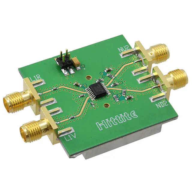
The circuit board used in the final application should use RF circuit design techniques. Signal lines should have 50
ohm impedance while the package ground leads and backside ground slug should be connected directly to the ground
plane similar to that shown. A sufficient number of via holes should be used to connect the top and bottom ground
planes. The evaluation circuit board shown is available from Hittite upon request.
List of Materials for
Evaluation PCB 105809 [1]
Item
Description
J1 - J4
PCB Mount SMA RF Connector
J5
2 mm DC Header
C1
4.7 μF Capacitor
C2, C5 - C7
100 pF Capacitor, 0402 Pkg.
C3, C4, C8
1000 pF Capacitor, 0603 Pkg.
R1[3], R2 [3]
4.3 Ohm Resistor, 0603 Pkg.
R3, R4, R5
200 Ohm Resistor, 0603 Pkg.
U1
HMC439QS16G / HMC439QS16GE
PCB [2]
105733 Eval Board
Evaluation PCB Circuit
FREQUENCY DIVIDERS & DETECTORS - SMT
6
Evaluation PCB
[1] Reference this number when ordering complete evaluation
PCB
[2] Circuit Board Material: Rogers 4350
[3] Choose values of R1 & R2 between 4.3 and 20 Ohms for
best noise performance
For price,
delivery,
and to placeCorporation:
orders: Analog Devices, Inc.,
For price, delivery, and to place orders, please contact
Hittite
Microwave
One Technology Way, P.O. Box 9106, Norwood, MA 02062-9106
20 Alpha Road, Chelmsford, MA 01824 Phone: Phone:
978-250-3343
978-250-3373
781-329-4700Fax:
• Order
online at www.analog.com
Application Support: Phone: 1-800-ANALOG-D
Order On-line at www.hittite.com
Information furnished by Analog Devices is believed to be accurate and reliable. However, no
responsibility is assumed by Analog Devices for its use, nor for any infringements of patents or other
rights of third parties that may result from its use. Specifications subject to change without notice. No
license is granted by implication or otherwise under any patent or patent rights of Analog Devices.
Trademarks and registered trademarks are the property of their respective owners.
6 - 101
�


 工商网监
湘ICP备2023018690号
工商网监
湘ICP备2023018690号
