ST3215SB32768H5HSZA1 数据手册
Specifications
Drawing No.
USY1N-H1-14429-00 1 / 9
Issued Date.
Dec,3,2014
Messrs: Digi-Key
Note: Part Number will be revised in case of specification change.
Product Type
Tuning Fork Crystal
Series
ST3215SB
Frequency
32.768 kHz
Customer Part Number
-
Customer Specification Number
-
ST3215SB32768H5HSZA1(CL=12.5pF)
ST3215SB32768E0HSZB1(CL=9.0pF)
KYOCERA Part Number
ST3215SB32768C0HSZA1(CL=7.0pF)
ST3215SB32768B0HSZA1(CL=6.0pF)
Remarks Pb-Free, RoHS Compliant, MSL 1 AEC Q200 conformity.
Customer Approval
Approval Signature
Approved Date
Department
Person in charge
Seller
KYOCERA Crystal Device Corporation
Manufacturer
KYOCERA Crystal Device Corporation
(Crystal Units Division)
(Sales Division)
6 Takeda Tobadono-cho, Fushimi-ku, Kyoto
612-8501 Japan
TEL. No. 075-604-3500
FAX. No. 075-604-3501
Design Department
KYOCERA Crystal Device Corporation
Crystal Unit Application Engineering Section
5850, Higashine-Koh, Higashine-Shi, Yamagata
999-3701 Japan
TEL. No. 0237-43-5611
FAX. No. 0237-43-5615
Quality Assurance
F.Mukae
Approved by
T.Soda
Checked by
A.Muraoka
Issued by
Y.Nozaki
Crystal Units Division
KYOCERA Crystal Device Corporation
KBS-5079F
�Drawing No.
USY1N-H1-14429-00
2/9
Revision History
Rev.No.
0
Description of revision
First Edition
Date
Approved by
Checked by
Issued by
Dec,3,2014
T.Soda
A.Muraoka
Y.Nozaki
KYOCERA Crystal Device Corporation
KBS-5079F
�Drawing No.
USY1N-H1-14429-00
3/9
1. APPLICATION
This specification sheet is applied to tuning fork crystal “ST3215SB”
for Automotive(Non-Safety Application).
2. PART NUMBER
ST3215SB32768H5HSZA1(CL=12.5pF)
ST3215SB32768E0HSZB1(CL=9.0pF)
ST3215SB32768C0HSZA1(CL=7.0pF)
ST3215SB32768B0HSZA1(CL=6.0pF)
3. RATINGS
Items
SYMB.
Rating
Unit
Operating Temperature range
Topr
-40~+125
deg. C
Storage Temperature range
Tstg
-55~+125
deg. C
4. CHARACTERISTICS
4-1 ELECTRICAL CHARACTERISTICS
Electrical Specification
Item
Symbol
Nominal Frequency
fo
Ta = 25 deg. C
Frequency Tolerance
df/fo
Ta = 25 deg.C
Condition
Min
Typ.
Max
Unit
20
ppm
32.768
-20
kHz
12.5
9.0
Load Capacitance
CL
Equivalent series resistance
R1
Q-Value
Q
13000
Motional capacitance
C1
Shunt capacitance
Turning point
pF
7.0
6.0
Secondary temperature
Coefficient
70
kΩ
3.0
4.4
fF
Co
0.6
1.2
pF
Tp
20
30
deg. C
K
-4.0
Aging
df/F
Drive level
DL
Insulation resistance
(between electrodes)
Ta = 25 deg. C
-8
-3
0.1
IR
500
2
10 /degC
3
ppm/year
0.5
µW
MΩ
4-2 MOISTURE SENSITIVITY LEVEL
Level 1
KYOCERA Crystal Device Corporation
KBS-5079F
�Drawing No.
USY1N-H1-14429-00
4/9
5. APPEARANCES, DIMENSIONS
OUTLINE DIMENSIONS (not to scale)
(TOP VIEW)
CONNECTION (TOP VIEW)
1.5± 0.1
3.2±0.10
4-(0.25)
(1)
(2)
0.8± 0.1
K925AA
(3) (4)
(Side View)
(Bottom View )
6-(0.1)
C0.25
4-(R0.15)
UNIT : mm
1.70
MARKING
(1) Identification
K
(2)
Date Code(3 Digits)
Last 1 digit of year and week Code.
(3)
Load Capacitance
(4)
Management number
(Example) 12.5pF A
9.0pF B
7.0pF C
6.0pF F
Alphabet or Number 1digit.
*The font of marking above is for reference purpose.
1.0
1.6
1.0
1.55
6. RECOMMENDED LAND PATTERN
3.6
KYOCERA Crystal Device Corporation
UNIT : mm
KBS-5079F
�Drawing No.
USY1N-H1-14429-00
5/9
7. TAPING
7.1 Specification
1. Material of the carrier tape is either polystyrene or A-PET (ESD).
2. Material of the cover tape is polyester (ESD).
3. The seal tape shall not cover the sprocket holes and not protrude from the carrier tape.
4. The R of the corner of each cavity is 0.2R MAX.
5. The alignment between centers of the cavities and sprocket holes is 0.05mm or less.
6. The orientation shall be checked from the top cover tape side.
7. Peeling force of the cover tape: 0.1 to 0.7N.
Leader and ending tape
SMD parts taped area
Empty compartment
Empty compartment
100mm min. sealed with
top cover tape
END
Top cover tape only
START
160mm min.
350mm min.
Leader
Ending
Direction (View from cover tape)
K925AA
K925AA
K925AA
K925AA
Feeding direction
Tensile strength
Peeling strength
Cover tape
Bending radius (50mm)
165 to 180˚
Feeding direction
Enboss tape
KYOCERA Crystal Device Corporation
KBS-5079F
�Drawing No.
7-2 Carrier tape specifications
USY1N-H1-14429-00
6/9
(Unit: mm)
B
H
C
J
E
G
F
A
L
Symbol
Dimension
A
B
2.0±0.1
4.0±0.1
G
H
12.0±0.3
1.0+0.1/-0
Symbol
Dimension
7-3 Reel specifications
N
T
D
C
D
E
F
4.0±0.1
5.5±0.1
1.75±0.1
J
L
N
T
3.6±0.1
1.8±0.1
1.0±0.1
0.3±0.05
1.5+0.1/-0
(Unit: mm)
W
R
S
U
Q
P
In the case of φ180 Reel
Symbol
P
φ180 +0/-1.5
Dimension
Symbol
S
φ21±0.8
Dimension
Q
φ60 +1.0/-0
U
2.0±0.5
R
φ13±0.2
W
13.0 +1.0/-0
KYOCERA Crystal Device Corporation
KBS-5079F
�Drawing No.
USY1N-H1-14429-00
7/9
8. RELIABILITY
(Reference: AEC-Q200 Rev. D. The solder used by examination is hereafter set to Sn-3Ag-0.5Cu.)
Frequency Stability and ESR Stability After stressing.
No
8.1
Stress
Reference
Additional Requirements
High Temperature Exposure MIL-STD-202
1000 hrs. at rated operating temperature (e.g. 85°C part can be stored for 1000 hrs
(Storage)
at 85°C. Same applies for 125°C). Unpowered.
Method 108
Measurement at 24±4 hours after test conclusion.
8.2
Temperature Cycling
JESD22
1000 cycles (-55°C to 125°C) Note: If -40°C , 85°C part the 1000 cycles will be at
Method JA-104
that temperature rating.
Measurement at 24±4 hours after test conclusion.
30min maximum dwell time at each temperature extreme. 1 min. maximum
transition time.
8.3
Biased Humidity
MIL-STD- 202
1000 hours 85°C/85%RH. Rated VDD applied with 1 MW and inverter in parallel,
Method 103
2X crystal CL capacitors between each crystal leg and GND.
Measurement at 24±4 hours after test conclusion.
8.4
Operational Life
MIL-STD- 202
Note: 1000 hrs @ 125°C. If 85°C part will be tested at that temperature. Rated
Method 108
VDD applied with 1 MW and inverter in parallel, 2X crystal CL capacitors between
each crystal leg and GND.
Measurement at 24±4 hours after test conclusion.
8.5
Terminal Strength (Leaded)
8.6
Resistance to Solvents
8.7
Mechanical Shock
MIL-STD- 202
Test leaded device lead integrity only. Conditions: A
Method 211
(227 g), C (227 g).
MIL-STD- 202
Note: Also aqueous wash chemical - OKEM clean or equivalent. Do not use
Method 215
banned solvents.
MIL-STD-202
Figure 1 of Method 213. Condition C
Method 213
8.8
Vibration
MIL-STD-202
5g's for 20 minutes 12 cycles each of 3 orientations.
Method 204
Note: Use 8"X5" PCB .031" thick with 7 secure points on one 8" side and 2 secure
points on corners of opposite sides. Parts mounted within 2" from any secure point.
Test from 10-2000 Hz.
8.9
Resistance to
MIL-STD-202
Condition B No pre-heat of samples. Note: Single Wave solder - Procedure 1 with
Soldering Heat
Method 210
solder within 1.5 mm of device body for Leaded. Procedure 1 except 230°C and
immerse only to level to cover terminals for SMD.
8.10 Solderability
J-STD-002
For both Leaded & SMD. Electrical Test not required. Magnification 50 X.
Conditions: Leaded: Method A @ 235°C, category 3.
SMD: a) Method B, 4 hrs @ 155°C dry heat @ 235°C
b) Method B @ 215°C category 3.
c) Method D category 3 @ 260°C.
8.11 Flammability
UL-94
V-0 or V-1 Acceptable
8.12 Board Flex
AEC Q200-005
60 sec minimum holding time.
8.13 Terminal Strength(SMD)
AEC Q200-006
The static load of 1.8Kg is added in the direction of the arrow and it maintains it in
the prime fields of parts for 60 sec with a scratch treatment device of R0.5.
KYOCERA Crystal Device Corporation
KBS-5079F
�Drawing No.
USY1N-H1-14429-00
8/9
9. REFLOW PROFILE
Pb-free reflow requirements for soldering heat resistance
KYOCERA Crystal Device Corporation
KBS-5079F
�Drawing No.
USY1N-H1-14429-00
9/9
10. Cautions for use
(1) Soldering upon mounting
Characteristics may be affected when Solder paste or conductive glue comes in contact with product lid or
surface.
(2) When using mounting machine
Please minimize the shock when using mounting machine to avoid any excess stress to the product.
(3) Conformity of a circuit
We strongly recommend to make sure that Negative resistance (Gain) of IC is designed to be 3 times the
ESR (Equivalent Series Resistance) of Crystal unit.
11. Storage conditions
Please store product in below conditions, and use within 6 months.
Temperature +18 to +30°C, and Humidity of 20 to 70 % in the packaging condition.
12. Manufacturing location
Kyocera Crystal Device Corporation Shiga Yohkaichi Plant
13. Quality Assurance
To be guaranteed by Kyocera Crystal Device Quality Assurance Division
14. Quality guarantee
When Kyocera Crystal Device Corporation rooted failure occurs within 1 year after its delivery, substitute product
will be arranged based on discussion. Quality guarantee of product after 1year of its delivery will be waivered.
15. Others
In case of any questions or opinions regarding the Specification, please have it in written manner
within 45 days after issued date.
KYOCERA Crystal Device Corporation
KBS-5079F
�
ST3215SB32768H5HSZA1 价格&库存
很抱歉,暂时无法提供与“ST3215SB32768H5HSZA1”相匹配的价格&库存,您可以联系我们找货
免费人工找货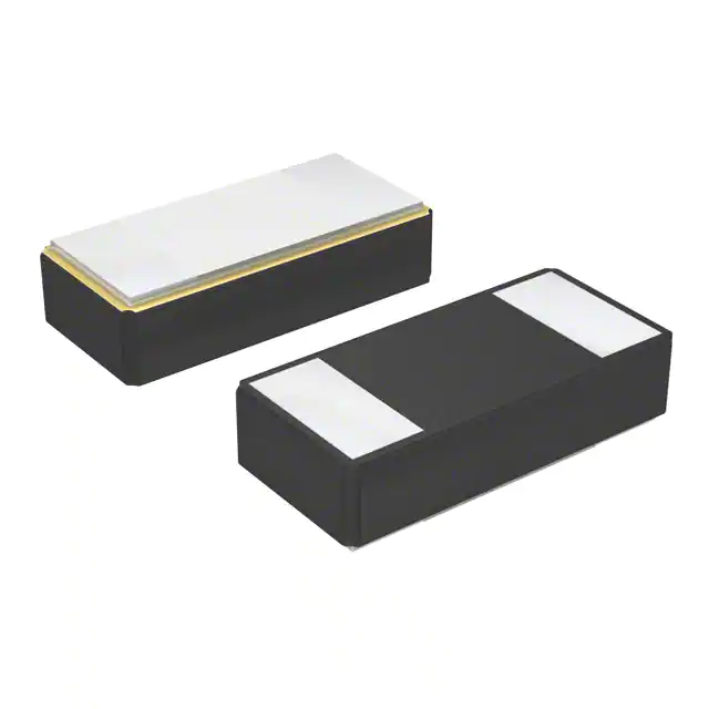


 工商网监
湘ICP备2023018690号
工商网监
湘ICP备2023018690号
