DAC5681
www.ti.com
SLLS864C – AUGUST 2007 – REVISED AUGUST 2012
16-BIT, 1.0 GSPS Digital-to-Analog Converter (DAC)
Check for Samples: DAC5681
FEATURES
DESCRIPTION
•
•
•
The DAC5681 is a 16-bit 1.0 GSPS digital-to-analog
converter (DAC) with wideband LVDS data input and
internal voltage reference. The DAC5681 offers
superior linearity and noise performance.
1
•
•
•
•
16-Bit Digital-to-Analog Converter (DAC)
1.0 GSPS Update Rate
16-Bit Wideband Input LVDS Data Bus
– 8 Sample Input FIFO
– On-Chip Delay Lock Loop
High Performance
– 73 dBc ACLR WCDMA TM1 at 180 MHz
On Chip 1.2 V Reference
Differential Scalable Output: 2 to 20 mA
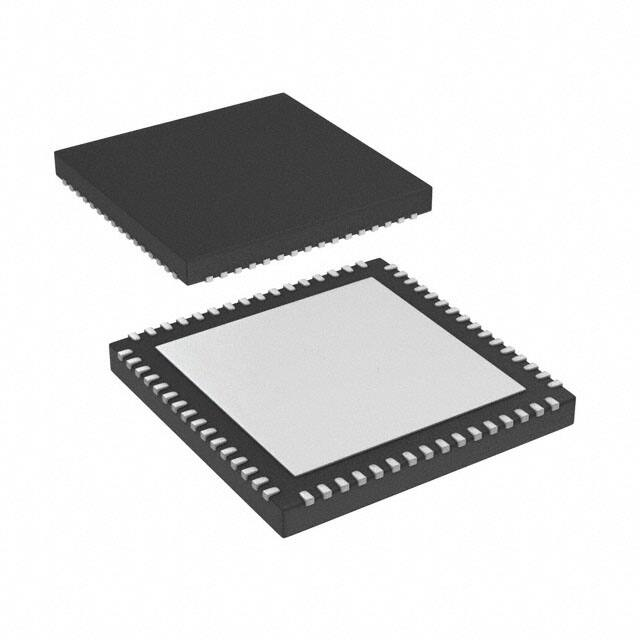
Package: 64-Pin 9 × 9 mm QFN
The DAC5681 integrates a wideband LVDS port with
on-chip termination, providing full 1.0 GSPS data
transfer into the DAC and lower EMI than traditional
CMOS data interfaces. An on-chip delay lock loop
(DLL) simplifies LVDS interfacing by providing skew
control for the LVDS input data clock.
The current-steering architecture of the DAC5681
consists of a segmented array of current sinking
switches directing up to 20mA of full-scale current to
complementary output nodes. An accurate on-chip
voltage reference is temperature-compensated and
delivers a stable 1.2-V reference voltage. Optionally,
an external reference may be used.
APPLICATIONS
•
•
•
•
•
•
•
Cellular Base Stations
Broadband Wireless Access (BWA)
WiMAX 802.16
Fixed Wireless Backhaul
Cable Modem Termination System (CMTS)
Medical / Test Instrumentation
Radar Systems
The DAC5681 is characterized for operation over the
industrial temperature range of –40°C to 85°C and is
available in a 64-pin QFN package. The device is pin
upgradeable to the other members of the family: the
DAC5681Z and DAC5682Z. The single-channel
DAC5681Z and dual-channel DAC5682Z both
provide optional 2x/4x interpolation and a clock
multiplying PLL.
ORDERING INFORMATION
TA
–40°C to 85°C
(1)
(2)
(3)
ORDER CODE
DAC5681IRGCT
DAC5681IRGCR
PACKAGE DRAWING/TYPE (1)
(2)
(3)
TRANSPORT MEDIA
QUANTITY
RGC / 64QFN Quad Flatpack NoLead
Tape and Reel
250
Tape and Reel
2000
Thermal Pad Size: 7,4 mm × 7,4 mm
MSL Peak Temperature: Level-3-260C-168 HR
For the most current package and ordering information, see the Package Option Addendum at the end of this document, or see the TI
website at www.ti.com.
1
Please be aware that an important notice concerning availability, standard warranty, and use in critical applications of
Texas Instruments semiconductor products and disclaimers thereto appears at the end of this data sheet.
PRODUCTION DATA information is current as of publication date.
Products conform to specifications per the terms of the Texas
Instruments standard warranty. Production processing does not
necessarily include testing of all parameters.
Copyright © 2007–2012, Texas Instruments Incorporated
�DAC5681
SLLS864C – AUGUST 2007 – REVISED AUGUST 2012
www.ti.com
These devices have limited built-in ESD protection. The leads should be shorted together or the device placed in conductive foam
during storage or handling to prevent electrostatic damage to the MOS gates.
CLKIN
Clock
Distribution
CLKINC
(3.3V)
AVDD
(1.8V)
VFUSE
(1.8V)
DVDD
(1.8V)
CLKVDD
FUNCTIONAL BLOCK DIAGRAM
EXTIO
1.2V
Reference
FDAC
EXTLO
BIASJ
DCLKP
Sync Disable
Delay Lock
Loop (DLL)
DCLKN
DLL Control
Mode Control
B
A
SYNCN
DAC Delay (0-3)
13
SYNC=’0->1'
(transition)
TXEnable=’1'
IOUTA1
16bit
DAC
IOUTA2
4
2
DAC Gain
100
SYNCP
16
16
Offset
D0N
DDR De-interleave
100
D0P
8 Sample FIFO
16
D15N
Delay Value
100
D15P
Sync & Control
SW_Sync
2
Submit Documentation Feedback
GND
(3.3V)
IOVDD
RESETB
SCLK
SDENB
SDO
SDIO
FIFO Sync Disable
Copyright © 2007–2012, Texas Instruments Incorporated
Product Folder Links: DAC5681
�DAC5681
www.ti.com
SLLS864C – AUGUST 2007 – REVISED AUGUST 2012
RESETB
AVDD
54
49
AVDD
DVDD
EXTIO
56
55
50
BIASJ
57
51
AVDD
EXTLO
IOUTA2
AVDD
60
59
IOUTA1
AVDD
AVDD
61
53
AVDD
62
52
DVDD
63
58
NC
64
DAC5681
RGC PACKAGE
(TOP VIEW)
CLKVDD
1
48
SDENB
CLKIN
2
47
SCLK
CLKINC
3
46
SDIO
GND
4
45
SDO
SYNCP
5
44
VFUSE
SYNCN
D15P
6
43
D0N
7
42
D0P
41
D1N
40
D1P
D15N
8
IOVDD
9
DVDD
10
39
DVDD
D14P
11
38
D2N
D14N
12
37
D2P
D13P
13
36
D3N
D13N
14
35
D3P
D12P
15
34
D4N
D12N
16
33
D4P
31
D5P
32
30
D6N
D5N
28
29
D6P
27
D7P
D7N
25
26
DCLKP
DCLKN
23
24
D8P
D8N
21
20
D10N
22
19
D10P
D9P
18
D11N
D9N
17
D11P
DAC5681
TERMINAL FUNCTIONS
TERMINAL
I/O
DESCRIPTION
NAME
NO.
AVDD
51, 54, 55,
59–62
I
BIASJ
57
O
Full-scale output current bias. For 20mA full-scale output current, connect a 960 Ω resistor to GND.
CLKIN
2
I
Positive external clock input with a self-bias of approximately CLKVDD/2.
CLKINC
3
I
Complementary external clock input. (See the CLKIN description)
CLKVDD
1
I
Internal clock buffer supply voltage. (1.8 V)
D[15..0]P
7, 11, 13,
15, 17, 19,
21, 23, 27,
29, 31, 33,
35, 37, 40,
42
I
LVDS positive input data bits 0 through 15. Each positive/negative LVDS pair has an internal 100 Ω
termination resistor. Order of bus can be reversed via rev_bus bit in CONFIG5 register. Data format
relative to DCLKP/N clock is Double Data Rate (DDR) with two data samples input per DCLKP/N clock. In
dual-channel mode, data for the A-channel is input while DCLKP is high.
D[15..0]N
8, 12, 14,
16, 18, 20,
22, 24, 28,
30, 32, 34,
36, 38, 41,
43
Analog supply voltage. (3.3V)
D15P is most significant data bit (MSB) – pin 7
D0P is least significant data bit (LSB) – pin 42
LVDS negative input data bits 0 through 15. (See D[15:0]P description above)
I
D15N is most significant data bit (MSB) – pin 8
D0N is least significant data bit (LSB) – pin 43
Submit Documentation Feedback
Copyright © 2007–2012, Texas Instruments Incorporated
Product Folder Links: DAC5681
3
�DAC5681
SLLS864C – AUGUST 2007 – REVISED AUGUST 2012
www.ti.com
TERMINAL FUNCTIONS (continued)
TERMINAL
NAME
NO.
I/O
DESCRIPTION
DCLKP
25
I
LVDS positive input clock. Unlike the other LVDS inputs, the DCLKP/N pair is self-biased to approximately
DVDD/2 and does not have an internal termination resistor in order to optimize operation of the DLL circuit.
See the “DLL Operation” section. For proper external termination, connect a 100 Ω resistor across LVDS
clock source lines followed by series 0.01 μF capacitors connected to each of DCLKP and DCLKN pins
(see Figure 17). For best performance, the resistor and capacitors should be placed as close as possible to
these pins.
DCLKN
26
I
LVDS negative input clock. (See the DCLKP description)
DVDD
10, 39, 50,
63
I
EXTIO
56
Used as external reference input when internal reference is disabled (i.e., EXTLO connected to AVDD).
I/O Used as 1.2V internal reference output when EXTLO = GND, requires a 0.1 μF decoupling capacitor to
AGND when used as reference output.
EXTLO
Digital supply voltage. (1.8 V)
58
O
Connect to GND for internal reference, or AVDD for external reference.
4, Thermal
Pad
I
Pin 4 and the Thermal Pad located on the bottom of the QFN package is ground for AVDD, DVDD and
IOVDD supplies.
IOUTA1
52
O
DAC current output. An offset binary data pattern of 0x0000 at the DAC input results in a full scale current
sink and the least positive voltage on the IOUTA1 pin. Similarly, a 0xFFFF data input results in a 0 mA
current sink and the most positive voltage on the IOUTA1 pin.
IOUTA2
53
O
DAC complementary current output. The IOUTA2 has the opposite behavior of the IOUTA1 described
above. An input data value of 0x0000 results in a 0mA sink and the most positive voltage on the IOUTA2
pin.
IOVDD
9
I
Digital I/O supply voltage (3.3V) for pins RESETB, SCLK, SDENB, SDIO, SDO.
NC
64
I
No Connect. Leave open for proper operation.
RESETB
49
I
Resets the chip when low. Internal pull-up.
SCLK
47
I
Serial interface clock. Internal pull-down.
SDENB
48
I
Active low serial data enable, always an input to the DAC5681. Internal pull-up.
SDIO
46
I/O
Bi-directional serial interface data in 3-pin mode (default). In 4-pin interface mode (CONFIG5 sif4), the
SDIO pin is an input only. Internal pull-down.
SDO
45
O
Uni-directional serial interface data in 4-pin mode (CONFIG5 sif4). The SDO pin is in high-impedance state
in 3-pin interface mode (default), but can optionally be used as a status output pin via CONFIG14
SDO_func_sel(2:0). Internal pull-down.
SYNCP
5
I
LVDS SYNC positive input data. The SYNCP/N LVDS pair has an internal 100 Ω termination resistor. By
default, the SYNCP/N input must be logic ‘1’ to enable a DAC analog output. See the LVDS SYNCP/N
Operation paragraph for a detailed description.
SYNCN
6
I
LVDS SYNC negative input data.
VFUSE
44
I
Digital supply voltage. (1.8V) Connect to DVDD pins for normal operation. This supply pin is also used
for factory fuse programming.
GND
4
Submit Documentation Feedback
Copyright © 2007–2012, Texas Instruments Incorporated
Product Folder Links: DAC5681
�DAC5681
www.ti.com
SLLS864C – AUGUST 2007 – REVISED AUGUST 2012
ABSOLUTE MAXIMUM RATINGS
over operating free-air temperature range (unless otherwise noted)
DVDD
Supply voltage range
(1)
(2)
VALUE
UNIT
–0.5 to 2.3
V
VFUSE (2)
–0.5 to 2.3
V
CLKVDD (2)
–0.5 to 2.3
V
–0.5 to 4
V
(2)
–0.5 to 4
V
AVDD to DVDD
–2 to 2.6
V
–0.5 to 0.5
V
AVDD (2)
IOVDD
CLKVDD to DVDD
IOVDD to AVDD
–0.5 to 0.5
V
–0.5 to DVDD + 0.5
V
–0.3 to 2.1
V
–0.5 to CLKVDD + 0.5
V
–0.5 to IOVDD + 0.5
V
–0.5 to AVDD + 0.5
V
–0.5 to AVDD + 0.5
V
Peak input current (any input)
20
mA
Peak total input current (all inputs)
–30
mA
Operating free-air temperature range, TA: DAC5681
–40 To 85
°C
Storage temperature range
–65 To 150
°C
D[15..0]P ,D[15..0]N, SYNCP, SYNCN
Terminal voltage range
(2)
DCLKP, DCLKN (2)
CLKIN, CLKINC
(2)
SDO, SDIO, SCLK, SDENB, RESETB
IOUTA1, IOUTA2
(2)
(2)
EXTIO, EXTLO, BIASJ (2)
(1)
(2)
Stresses beyond those listed under absolute maximum ratings may cause permanent damage to the device. These are stress ratings
only, and functional operation of these or any other conditions beyond those indicated under recommended operating conditions is not
implied. Exposure to absolute-maximum-rated conditions for extended periods may affect device reliability.
Measured with respect to GND.
THERMAL CHARACTERISTICS
over operating free-air temperature range (unless otherwise noted)
THERMAL CONDUCTIVITY
TJ
Maximum junction temperature
(1)
64ld QFN
UNIT
125
°C
Theta junction-to-ambient (still air)
20
Theta junction-to-ambient (150 lfm)
16
θJC
Theta junction-to-case
7
°C/W
θJP
Theta junction-to-pad
0.2
°C/W
θJA
(1)
°C/W
Air flow or heat sinking reduces θJA and may be required for sustained operation at 85° under maximum operating conditions.
Submit Documentation Feedback
Copyright © 2007–2012, Texas Instruments Incorporated
Product Folder Links: DAC5681
5
�DAC5681
SLLS864C – AUGUST 2007 – REVISED AUGUST 2012
www.ti.com
ELECTRICAL CHARACTERISTICS — DC SPECIFICATION
over operating free-air temperature range , AVDD = 3.3 V, CLKVDD = 1.8 V, IOVDD = 3.3 V, DVDD = 1.8 V, IoutFS = 20 mA
(unless otherwise noted)
PARAMETER
TEST CONDITIONS
RESOLUTION
DC ACCURACY
MIN
TYP
MAX
16
UNIT
Bits
(1)
INL
Integral nonlinearity
DNL
Differential nonlinearity
1 LSB = IOUTFS/216
±4
LSB
±2
ANALOG OUTPUT
Coarse gain linearity
±0.04
LSB
0.01
%FSR
With external reference
1
%FSR
With internal reference
0.7
%FSR
Offset error
Mid code offset
Gain error
Gain error
Minimum full scale output current (2)
2
Maximum full scale output current (2)
20
Output Compliance range (3)
IOUTFS = 20 mA
AVDD
–0.5V
Output resistance
Output capacitance
mA
AVDD
+ 0.5V
V
300
kΩ
5
pF
REFERENCE OUTPUT
Vref
Reference voltage
1.14
Reference output current (4)
1.2
1.26
100
V
nA
REFERENCE INPUT
VEXTIO
Input voltage range
0.1
Input resistance
Small signal bandwidth
1.25
1
CONFIG6: BiasLPF_A = 0
95
CONFIG6: BiasLPF_A = 1
472
Input capacitance
V
MΩ
kHz
100
pF
±1
ppm of
FSR/°C
TEMPERATURE COEFFICIENTS
Offset drift
Gain drift
With external reference
±15
With internal reference
±30
ppm of
FSR/°C
±8
ppm/°C
Reference voltage drift
POWER SUPPLY
Analog supply voltage, AVDD
3.0
3.3
3.6
V
Digital supply voltage, DVDD
1.71
1.8
2.15
V
Clock supply voltage, CLKVDD
1.71
1.8
2.15
V
3.0
3.3
3.6
V
I/O supply voltage, IOVDD
I(AVDD)
Analog supply current
67
mA
I(DVDD)
Digital supply current
191
mA
I(CLKVDD)
Clock supply current
15
mA
I(IOVDD)
IO supply current
4
mA
(1)
(2)
(3)
(4)
6
Mode 1 (below)
Measured differential across IOUTA1 and IOUTA2 with 25 Ω each to AVDD.
Nominal full-scale current, IoutFS, equals 16 × IBIAS current.
The lower limit of the output compliance is determined by the CMOS process. Exceeding this limit may result in transistor breakdown,
resulting in reduced reliability of the DAC5681 device. The upper limit of the output compliance is determined by the load resistors and
full-scale output current. Exceeding the upper limit adversely affects distortion performance and integral nonlinearity.
Use an external buffer amplifier with high impedance input to drive any external load.
Submit Documentation Feedback
Copyright © 2007–2012, Texas Instruments Incorporated
Product Folder Links: DAC5681
�DAC5681
www.ti.com
SLLS864C – AUGUST 2007 – REVISED AUGUST 2012
ELECTRICAL CHARACTERISTICS — DC SPECIFICATION (continued)
over operating free-air temperature range , AVDD = 3.3 V, CLKVDD = 1.8 V, IOVDD = 3.3 V, DVDD = 1.8 V, IoutFS = 20 mA
(unless otherwise noted)
PARAMETER
I(AVDD)
Sleep mode, AVDD supply current
I(DVDD)
Sleep mode, DVDD supply current
I(CLKVDD)
Sleep mode, CLKVDD supply current
I(IOVDD)
Sleep mode, IOVDD supply current
AVDD + IOVDD current, 3.3V
DVDD + CLKVDD current, 1.8V
TEST CONDITIONS
MIN
Mode 3 (below)
Mode 1: CLKIN = 1000 MHz
IF = 40 MHz
Single Tone, 0 dBFS
DVDD + CLKVDD current, 1.8V
P
DVDD + CLKVDD current, 1.8V
Mode 2: CLKIN = 500 MHz
IF = 40 MHz
Single Tone, 0 dBFS
DVDD + CLKVDD current, 1.8V
Mode 3: CLKIN = 1000 MHz
DAC on SLEEP, Static Data Pattern
Mode 4: CLKIN = OFF
DAC on SLEEP, Static Data Pattern
Power Dissipation
PSRR
Power supply rejection ratio
T
Operating range
91
mA
15
mA
1.5
mA
71
mA
mW
mA
111
mA
435
mW
3
mA
106
mA
200
mW
3
mA
6
mA
20
DC tested
mA
650
71
Power Dissipation
AVDD + IOVDD current, 3.3V
UNIT
mA
605
Power Dissipation
AVDD + IOVDD current, 3.3V
MAX
1.5
206
Power Dissipation
AVDD + IOVDD current, 3.3V
TYP
30
mW
–0.2
0.2
%FSR/V
–40
85
°C
Submit Documentation Feedback
Copyright © 2007–2012, Texas Instruments Incorporated
Product Folder Links: DAC5681
7
�DAC5681
SLLS864C – AUGUST 2007 – REVISED AUGUST 2012
www.ti.com
ELECTRICAL CHARACTERISTICS — AC SPECIFICATION (1)
Over recommended operating free-air temperature range, AVDD, IOVDD = 3.3 V, CLKVDD, DVDD = 1.8 V, IOUTFS = 20 mA,
4:1 transformer output termination, 50Ω doubly terminated load (unless otherwise noted)
PARAMETER
TEST CONDITIONS
MIN
TYP MAX
UNIT
ANALOG OUTPUT
fCLK
Maximum output update rate
ts(DAC)
Output settling time to 0.1%
Transition: Code 0x0000 to 0xFFFF
1000
tpd
Output propagation delay
DAC output is updated on falling edge of DAC clock.
Does not include Digital Latency (see below).
tr(IOUT)
tf(IOUT)
MSPS
10.4
ns
2.5
ns
Output rise time 10% to 90%
220
ps
Output fall time 90% to 10%
220
ps
76
DAC
clock
cycles
BiasLPF_A enabled; register 0x06, Bit 3 set to 1.
8
μs
BiasLPF_A disabled; register 0x06, Bit 3 set to 0.
80
μs
BiasLPF_A enabled; register 0x06, Bit 3 set to 1.
8
μs
BiasLPF_A disabled; register 0x06, Bit 3 set to 0.
80
μs
CLKIN = 500 MHz, IF = 5.1 MHz,
First Nyquist Zone < fDATA/2
81
CLKIN = 1000 MHz, IF = 5.1 MHz,
First Nyquist Zone < fDATA/2
80
CLKIN = 1000 MHz, IF = 20.1 MHz,
First Nyquist Zone < fDATA/2
77
CLKIN = 500 MHZ, Single tone, 0 dBFS,
IF = 20.1 MHz
75
CLKIN = 1000 MHZ, Single tone, 0 dBFS,
IF = 20.1 MHz
70
CLKIN = 1000 MHZ, Single tone, 0 dBFS,
IF = 70.1 MHz
66
CLKIN = 1000 MHZ, Single tone, 0 dBFS,
IF = 180 MHz
60
CLKIN = 1000 MHZ, Single tone, 0 dBFS,
IF = 300.2 MHz
60
CLKIN = 1000 MHZ, Four tone, each -12 dBFS,
IF = 24.7, 24.9, 25.1 and 25.3 MHz
73
CLKIN = 1000 MHZ, IF = 20.1 and 21.1 MHz
88
CLKIN = 1000 MHZ, IF = 70.1 and 71.1 MHz
75
CLKIN = 1000 MHZ, IF = 150.1 and 151.1 MHz
67
CLKIN = 1000 MHz, IF = 298.4, 299.2, 300.8 and 301.6 MHz
64
Digital Latency
DAC Wake-up Time (2)
Power-up
Time
DAC Sleep Time
(3)
AC PERFORMANCE
SFDR
Spurious free dynamic range
SNR
Signal-to-noise ratio
Third-order two-tone
intermodulation
(each tone at –6 dBFS)
IMD3
Four-tone intermodulation
(each tone at –12 dBFS)
IMD
dBc
Single carrier, baseband, CLKIN = 983.04 MHz
ACLR (4)
Adjacent channel leakage ratio
Noise floor (5)
(1)
(2)
(3)
(4)
(5)
8
dBc
80
dBc
dBc
83
Single carrier, IF = 180 MHz, CLKIN = 983.04 MHz
73
Four carrier, IF = 180 MHz, CLKIN = 983.04 MHz
68
Four carrier, IF = 275 MHz, CLKIN = 983.04 MHz
66
50-MHz offset, 1-MHz BW, Single Carrier, baseband,
CLKIN = 983.04
93
50-MHz offset, 1-MHz BW, Four Carrier, baseband,
CLKIN = 983.04
85
dBc
dBc
Measured single-ended into 50 Ω load.
IOUT current settling to 1% of IOUTFS. Measured from SDENB rising edge; Register 0x06, toggle Bit 4 from 1 to 0.
IOUT current settling to less than 1% of IOUTFS. Measured from SDENB rising edge; Register 0x06, toggle Bit 4 from 0 to 1.
W-CDMA with 3.84 MHz BW, 5-MHz spacing, centered at IF. TESTMODEL 1, 10 ms
Carrier power measured in 3.84 MHz BW.
Submit Documentation Feedback
Copyright © 2007–2012, Texas Instruments Incorporated
Product Folder Links: DAC5681
�DAC5681
www.ti.com
SLLS864C – AUGUST 2007 – REVISED AUGUST 2012
ELECTRICAL CHARACTERISTICS (DIGITAL SPECIFICATIONS)
over recommended operating free-air temperature range, AVDD, IOVDD = 3.3V, CLKVDD, DVDD = 1.8V.
PARAMETER
TEST CONDITIONS
LVDS INTERFACE: D[15:0]P/N, SYNCP/N, DCLKP/N
MIN
TYP MAX
UNIT
(1)
VA,B+
Logic high differential
input voltage threshold
175
mV
VA,B–
Logic low differential
input voltage threshold
–175
mV
VCOM1
Input Common Mode
VCOM2
Input Common Mode
ZT
Internal termination
CL
LVDS Input
capacitance
tS, tH
DCLK to Data
SYNCP/N, D[15:0]P/N only
1.0
DCLKP/N only
SYNCP/N, D[15:0]P/N only
85
DCLKP/N: 0 to 125MHz (see Figure 20) DLL
Disabled, CONFIG5 DLL_bypass = 1, CONFIG10
= '00000000'
DCLKP/N = 200 MHz
DCLKP/N = 250 MHz
DCLK to Data Skew (2)
DLL Enabled,
CONFIG5 DLL_bypass =
0,
DDR format
DCLKP/N = 300 MHz
DCLKP/N = 350 MHz
DCLKP/N = 400 MHz
DCLKP/N = 450 MHz
DCLKP/N = 500 MHz
fDATA
Input data rate
supported
DLL Operating
Frequency (DCLKP/N
Frequency)
(1)
(2)
110
V
Ω
135
2
DCLKP/N = 150 MHz
tSKEW(A),
tSKEW(B)
V
DVDD
÷2
Setup_min
1100
Hold_min
–600
Positive
1000
Negative
–1800
Positive
–1300
Positive
600
Negative
–1000
Positive
450
Negative
–800
Positive
400
Negative
–700
Positive
300
Negative
–600
Positive
300
Negative
–500
Positive
350
Negative
–300
DLL Disabled, CONFIG5 DLL_bypass = 1, DDR format,
DCLKP frequency:


 工商网监
湘ICP备2023018690号
工商网监
湘ICP备2023018690号
