CII Mid-Range Relays
FCA-210 Series, 10 Amperes, DPDT
Product Facts
n
Hermetically Sealed
n
All Welded Construction
n
Balanced Force
n
Permanent Magnet Drive
n
Contacts — Silver Cadmium
Oxide with Gold Plating
n
Coils for DC, 50 to 400Hz
and 400Hz AC
n
Weight 1.6 ounces max.
(45.4 grams)
n
manufacture other versions
of this relay:
The Series FCA-210 relay
is a polarized single-side
stable design, where the
flux from a permanent
magnet provides the
armature holding force in
the deactivated state, and
its flux path is switched and
combined with the coil flux
in the operated state.
This results in appreciably
increased contact pressure
in both states over that of a
spring return nonpolar
design. We also
FCA-410 — 10 Ampere
4PDT Relay
FCA-610 — 10 Ampere
6 PDT Relay
Available:
FCA-215 — 15 Ampere
DPDT Relay, Has the same
specifications as the
FCA-210 except is rated at
15 amps. (Commercial Only)
Contact Rating — Amperes
Ratings Are Continuous Duty
Qualified to M83536/9, /10
Type of
Load
Life (Min.)
Cycles x 103
28 VDC
115VAC
400Hz
Resistive
Inductive
Motor
Lamp
100
20
100
100
10
8
4
2
10
8
4
2
115/200VAC 3Ø
400Hz
60Hz*
10
2.5
8
2.5
4
2.0
2
1
*60 Hz loads rated for 10,000 operations
Overload Current — 40 AMPS DC, 60 AMPS 400Hz
Rupture Current — 50 AMPS DC, 80 AMPS 400Hz
Contact Make Bounce —1 MILLISECOND AT NOMINAL VOLTAGE
Max. Contact Drop at 10 Amps — INITIAL 0.100 VOLTS
End of Life — 0.125 VOLTS
General Specifications
Temperature Rating —
-70˚C TO + 125˚C
Altitude — 300,000 Feet
Shock* —
Z, Y, & X Enclosures —
200 g for 6 mS
W & M Enclosures (Stud Mtg.) —
100 g for 6 mS
Vibration, Sinusoidal* —
Z, Y, & X Enclosures —
30 g 33-3000Hz
W & M Enclosures (Stud Mtg.) —
20 g 33-3000Hz
Vibration, Random* —
Z, Y, & X Enclosures —
0.4 g2/Hz 50-2000Hz
W & M Enclosures (Stud Mtg.) —
0.2 g2/Hz 50-2000Hz
Dielectric Strength —
At Sea Level —
All circuits to ground and circuit to
circuit — 1250 V rms
Coil to ground — 1000 V rms
At 80,000 Feet — 350 V rms
Insulation Resistance —
Initial (500 VDC) — 100 MΩ Min.
After Life or Environmental Tests —
50 MΩ Min.
Operate Time at Nominal
Voltage —
DC Relays — 10 ms or less
AC Relays — 15 ms or less
Release Time at Nominal
Voltage —
DC Relays — 10 ms or less
AC Relays — 50 ms or less
* Max. contact opening under vibration
or shock 10 microseconds
Coil Data
Coil
Code
1
2
3
4 (A)
5
6
7
8
9
NOTE: Only DC Coil Models are
QPL Approved.
A.
B.
C.
D.
E.
Nominal
Voltages
Freq.
Hz
DC Res.
AC Amps (B)
6
12
28
28
48
28
28
115
115
DC
DC
DC
DC
DC
400Hz
50/400Hz
400 Hz
50/400 Hz
20 Ω
80 Ω
320 Ω
320 Ω
920 Ω
180 mA
100 mA
40 mA
30 mA
Over Temperature Range
Pickup or
Dropout or
Must Hold
Below Volts
Above Volts
Voltage (C)
4.5
0.3
2.5
9.0
0.75
4.5
18.0
1.5
7.0
18.0
1.5
7.0
32.0
2.5
14.0
22.0
1.25
10.0
22.0
1.25
10.0
90.0
5.0
40.0
95.0
5.0
40.0
CODE 4 COILS HAVE BACK EMF SUPPRESSION TO 42 VOLTS MAX.
DC COIL RESISTANCE ± 10% AT 25˚C; AC COIL MAX. CURRENT AT NOMINAL VOLTAGE.
RELAY WILL STAY IN PICKED-UP STATE DOWN TO MUST HOLD VOLTAGES SHOWN.
MAX. OVERVOLTAGE: 6 & 12 VDC COILS 120% OF NOMINAL; ALL OTHERS 110% OF NOMINAL.
COILS AVAILABLE FOR OTHER VOLTAGES AND FOR AC 50/60HZ.
5–12
Catalog 5-1773450-5
Revised 3-13
www.te.com
Dimensions are shown for
reference purposes only.
Specifications subject
to change.
Dimensions are in millimeters
unless otherwise specified.
USA: +1 800 522 6752
Asia Pacific: +86 0 400 820 6015
UK: +44 800 267 666
For additional support numbers
please visit www.te.com
�CII Mid-Range Relays
FCA-210 Series, 10 Amperes, DPDT (Continued)
Below are shown the standard terminal types and the enclosures available. Specify the assembly as indicated under How
To Order. Dimensions are shown in inches ± .010 and (Millimeters ± .25).
Enclosures
Terminals
SOCKET PINS ARE GOLD PLATED
POLARIZING PINS ARE TIN/LEAD PLATED
CIRCUIT BOARD PINS ARE TIN/LEAD PLATED
DIMENSIONS EXCEPT AS NOTED:
INCHES ± .010 (MILLIMETERS ± .25)
CODE
“A” Socket Pins - All DC Coils
.050 ± .005
(1.27 ± (.127)
Silicone
Rubber
Gasket
.270
(6.86)
.300
(7.62)
Socket Pins 115 VAC
CODE
“D”
.050 ± .005
(1.27 ± (13)
Silicone
Rubber
Gasket
.270
(6.86)
.330 ±.030
(8.83) ± (.76)
+.006
.115 - (.010)
(2.92) +(.152)
- (.254)
.070 (1.78)
.050 (1.27)
-X2
+X1
.525 Max.
(13.34)
Socket Pins 28 VAC Coils
Same as Code “D” Except polarizing
Pin turned 90˚ to this plane.
POLARIZING PIN
.062 ±.001 Dia. Pin
(1.57 ± .02) 8 Plcs
.270
(6.86)
“A”
Max.
1.025 Max.
(26.04)
.062 ± .001 Dia. Pin
(1.57 ± .02)
BLUE BEAD
CODE
“E”
CODE
“B”
Circuit Board Pins - All DC Coils
“A” AC Coils 1.125 in. (28.57) Max.
DC Coils 1.010 in. (25.65) Max.
.062
.027 ±.003
(1.57) (.69) ± (.08)
Dia.
Polar
(1.57 +.05
- .02) Pin
BLUE BEAD
Dimensions: Inches ± .010 (mm ± .25)
CODE
“Z”
.062 +.002
- .001 Dia.
-X2
All Enclosures have Cupro-Nickel
Cans bright acid tin/lead plated after
assembly to terminal headers.
CODE
“Y” “A”
MAX.
Circuit Board Pins
115 VAC Coils
CODE
“F”
.156
(3.96)
FULL R
4 PLCS
.270
(6.86)
-X2
.062 +.002 Dia.
- .001
(1.57 +.05) Polar
- .02 Pin
BLUE BEAD
Solder Hook Terminals
+.006
.115 - (.010)
(2.92) +(.152)
- (.254)
CODE
“X” “A”
-X2
.062 +002 Dia. Pin
-.001
Circuit Board Pins
28 VAC Coils
.550
(13.97)
AC Coils
1.025 Max.
(26.04)
1.396
(35.46)
1.446
(36.73)
FULL R
4 PLCS
.312
CODE
(7.92)
"W" 6-32 UNC-2A
.375
(9.52)
2 Studs *
-X2
0.80 DIA
(2.03)
+.002
.062 - .001 Dia. Term.
(1.57)+.05 8 Plcs
- .02
CODE
“H”
90˚ Solder Pins
All Pins Bright Acid Tin/lead
.400
(10.61)
.200
(5.08)
.200
BLUE BEAD
(5.08)
+.002
.062 - .001 Dia.
+X1
Catalog 5-1773450-5
Revised 3-13
www.te.com
Dimensions are shown for
reference purposes only.
Specifications subject
to change.
Dimensions are in millimeters
unless otherwise specified.
.031
(.787)
“A”
MAX.
1.025 Max.
(26.04)
.200
(5.08)
.257
(6.52)
.525 Max.
(13.34)
.100 R Typ.
BLUE BEAD
.040
(1.02)
1.718 Max.
(43.64)
POLARIZING PIN
.300 ± .020
(7.62)± .51
.500
(12.70)
DC Coils
.525 Max.
(13.34)
Same as Code “F” Except polarizing
Pin turned 90˚ to this plane.
HOOK TERMINALS TIN/LEAD PLATED
.150
(3.8)
.375
(9.52)
Max.
+X1
5
1.718 Max.
(43.64)
.062
.027 ±.003
(1.57) (.69) ± (.08)
Dia.
CODE
“G”
.375
(9.52)
.070 (1.78)
.050 (1.27)
BLUE BEAD
CODE
“C”
.150
(3.8)
.525 Max.
(13.34)
.330 ±.030
(8.83) ± (.76)
.062 ±.001 Dia. Pin
(1.57 ± .02) 8 Plcs
.040
(1.02)
.625
(5.88)
.200
(5.08)
*Metric threads available,To specify use M in place of W
USA: +1 800 522 6752
Asia Pacific: +86 0 400 820 6015
UK: +44 800 267 666
For additional support numbers
please visit www.te.com
5–13
CII Mid-Range Relays
.300
(7.62)
1.025 Max.
(26.04)
1.446
(36.73)
1.396
(35.46)
�CII Mid-Range Relays
FCA-210 Series, 10 Amperes, DPDT (Continued)
Terminal Wiring
DC Coils with
Transient Suppression
DC Coils
-
X2
2
1
3
B
+
X1
A
+
BLUE BEAD
-
X2
2
3
+
+
X1
AC Coils
28 VAC
POLARIZING
PIN
POLARIZING
PIN
POLARIZING
PIN
POLARIZING
PIN
1
AC Coils
115 VAC
1
B
A
BLUE BEAD
NOTE: Polarity must be observed with DC coil supply.
Relay is polarized with a permanent magnet and will not
operate or be damaged by reverse polarity.
Diodes used in transient suppression and in AC rectifier
circuits have peak inverse voltage rating of 600 VDC
minimum. Zener diodes have a minimum rating of 1 watt.
Terminal designations are for reference only and do not
appear on the header.
2
X2
1
3
2
X2
AC
X1
AC
X1
A
BLUE BEAD
BLUE BEAD
.100
(2.54)
.200
(5.08)
A1
-X2
A2
A3
B
A
.100
(2.54)
+X1
.100
(2.54)
.200
(5.08)
.400
(10.16)
.600
(15.24)
TERMINAL VIEW
HOW TO ORDER
FCA-215FCA-210-A Y 4
RELAY TYPE
TERMINALS (Socket Pins, DC Coil)
ENCLOSURE (With Flanges)
COIL (28 VDC With Transient Suppression).
NOTE: Only DC coil models are QPL Approved
* The part number example shown on this page is for catalog items. For a list of specific QPL part numbers, please see the index in Section 15.
5–14
Catalog 5-1773450-5
Revised 3-13
www.te.com
Dimensions are shown for
reference purposes only.
Specifications subject
to change.
Dimensions are in millimeters
unless otherwise specified.
USA: +1 800 522 6752
Asia Pacific: +86 0 400 820 6015
UK: +44 800 267 666
3
B
B
For additional support numbers
please visit www.te.com
A
�
很抱歉,暂时无法提供与“FCA-210-DY9”相匹配的价格&库存,您可以联系我们找货
免费人工找货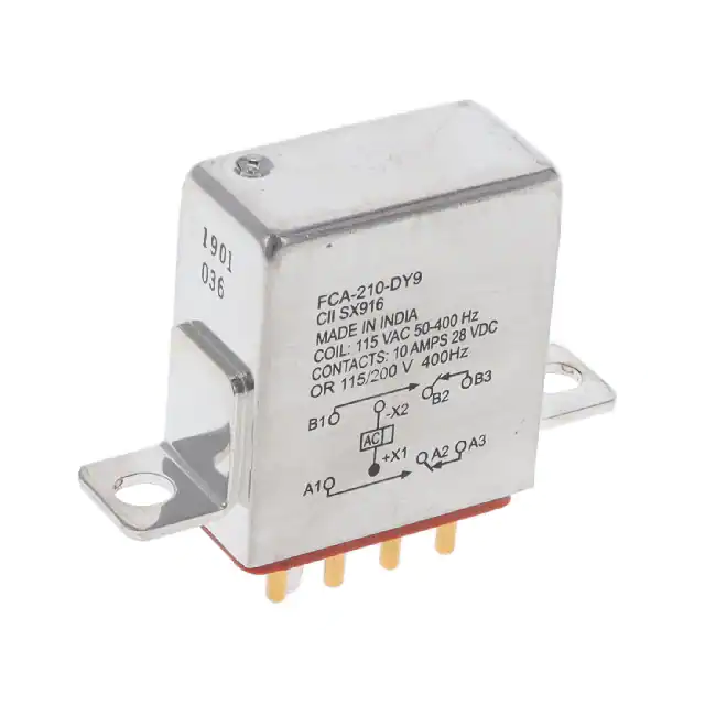


 工商网监
湘ICP备2023018690号
工商网监
湘ICP备2023018690号
