D1U3CS-W-1300F-12-HC4EC 数据手册
www.murata-ps.com
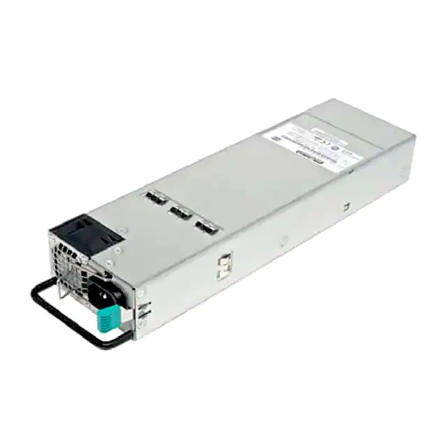
D1U3CS-W-1300F-12-Hx4EC Series
81mm Front End AC-DC Power Converter
PRODUCT OVERVIEW
The D1U3CS-W-1300F-12-Hx4EC are high efficiency 1300W power factor corrected front end supplies with a 12V main
output and a 5V or 3.3V (20W) standby. Active current sharing is provided to allow up to eight (8) supplies to be operated
in parallel. The supplies may be hot plugged and include integral isolation devices.
The power modules are fully protected from overload and overvoltage and are able to auto-recover from overtemperature
faults. Status LEDS are provided on the front panel and additional control and status reporting is provided by hardware
logic signals and via a PMBus™ digital interface.
A low profile sub 1U height enclosure provides a power density of >23W/in3 that is ideal for delivering reliable, efficient
power to servers, workstations, storage systems and other 12V distributed power systems.
ORDERING GUIDE
FEATURES
Power Output
AC Line & Temp
AC Line & Temp
(108-264V; 40°C)
(90-264V; 50°C)
Model Number
Extended Power Range to 1300W
1.57" (1U) x 11.0" x 3.2"
92% efficiency at 50% FL
12VDC Main output
3.3VSB or 5VSB output (20W)
>23W/in3 power density
N+1 Redundancy Capable; hot plug/swap (up to
8 modules in parallel)
Active current sharing on 12V main output;
integral MOSFET ORING
Over-Voltage, Over-Current; Over-Temperature
Protection
Internal variable speed cooling fans
D1U3CS-W-1300F-12-HA4EC
D1U3CS-W-1300F-12-HC4EC
INPUT CHARACTERISTICS
Parameter
Voltage Operating Range
Input Frequency
Turn-on Input Voltage
Turn-off Input Voltage
Maximum Current @ VIN = 200Vac
Maximum Current @ VIN = 90Vac
Inrush Current
Power Factor
Efficiency (230Vac) excluding fan load
PMBus™ Power Management Bus
www.murata-ps.com/en/3d/acdc.html
www.murata-ps.com/en/3d/acdc.html
www.murata-ps.com/en/3d/acdc.html
www.murata-ps.com/en/3d/acdc.html
www.murata-ps.com/en/3d/acdc.html
1
For full details go to
www.murata-ps.com/rohs
1200W
Conditions
Ramp Up
Ramp Down
1300W @ 40°C (max)
1200W @ 50°C (max)
Cold start between 0 to 200ms
At 230Vac; FL
20% FL
50% FL
100% FL
OUTPUT VOLTAGE CHARATERISTICS
Output
Parameter
Voltage
Voltage Set Point Accuracy
Line & Load Regulation
Ripple & Noise1
12V
Output Current (230Vac)
Output Current (120Vac)
Output Current (90Vac)
Load Capacitance
Voltage Set Point
Line & Load Regulation
3.3VSB
Ripple Voltage & Noise1
Output Current
Load Capacitance
Voltage Set Point
Line & Load Regulation
5VSB
Ripple Voltage & Noise1
Output Current
Load Capacitance
RoHS Compliant
Available now at
www.murata-ps.com/en/3d/acdc.html
1300W
Conditions
Main
Output
Standby
Output
Airflow
12V
5V
3.3V
Back to Front
Min
90
47
81
70.5
Typ
115/230
50/60
85
74.3
Max
264
63
89
78.0
8
15
25
Units
Vac
Hz
Vac
Arms
Apk
0.99
88
92
92
Min
%
Typ
Max
12
11.4
12.6
150
108.3
108.3
100
30,000
20MHz Bandwidth
0
3.3
3.2
3.4
100
6
10,000
20MHz Bandwidth
0
5.0
4.85
20MHz Bandwidth
0
5.1
50
4
10,000
Units
Vdc
mV P-P
A
μF
Vdc
mV P-P
A
μF
Vdc
mV P-P
A
μF
Ripple and noise are measurements are to be performed with a parallel combination of a 0.1μF ceramic capacitor and 10μF tantalum
capacitance on each of the power module output measurement nodes. A short coaxial cable shall be used.
CB
Test Certificate
and Test Report
www.murata-ps.com/support
D1U3CS-W-1300F-12-Hx4EC.A01 Page 1 of 5
�D1U3CS-W-1300F-12-Hx4EC Series
81mm Front End AC-DC Power Converter
OUTPUT CHARACTERISTICS
Parameter
Remote Sense
Output Rise (Monotonic)
Startup Time
Transient Response
Current Sharing Accuracy (up to 8 in parallel)
Hot Swap Transients
Hold Up Time
ENVIRONMENTAL CHARACTERISTICS
Parameter
Storage Temperature Range
Operating Temperature Range
Operating Humidity
Storage Humidity
Altitude (no derating at 40°C)
Shock
Sinusoidal Vibration
MTBF
Conditions
Compensation at full load (total loop for positive & negative connections)
10% to 95% rise time
AC Ramp Up
PS_ON activation
12V, 50-100% step load 1A/μs
3.3/5VSB 50-100% step load 1A/μs
At 100% load
FL (Full Load)
Conditions
Non-Condensing
1200W
1300W
Non-Condensing
Min
Max
120
No voltage excursion
1.5
2.5
150
600
165/250
±7
5
12
Min
-40
0
0
5
5
3000
Operating
Operational, 2.0G; 5-500Hz
Telcordia SR-332 M1C1 @ 40°C
Typ
Typ
Max
70
50
40
90
95
30
500
Units
mV
s
ms
mV
%
%
ms
Units
°C
%
m
G
K Hours
CSA/UL C22.2 No.60950-1-07, Amendment 1_2011
ANSI/UL 60950-1-2011
Safety Approvals (Standards)
IEC 60950-1:2005, (2nd Edition) + A1:2009
EN 60950-1:2006 + A11:2009 +A1 :2010 +A12:2011
CE Marking per LVD DIRECTIVE 2006/95/ECS
Input Fusing
Switching Frequency
Material Flammability
Weight
PROTECTION CHARACTERISTICS
Output Voltage
Parameter
N/A
Over-Temperature
Over-Voltage
12V (Main)
Over-Current (1300W)
Over-Current (1200W)
Over-Voltage
3.3VSB
Over-Current
Over-Voltage
5VSB
Over-Current
ISOLATION CHARACTERISTICS
Parameter
Insulation Safety Rating/Test Voltage
Isolation
Internal 16A/250V rated fast blow in AC line
90KHz for the PFC Boost Converter
130KHZ for the Main Output Converter
UL94-V0
3.15/1.43 Lbs/kg
Conditions
Auto re-start
Latching
Latching
Latching
Latching
Auto-recovery
Latching
Auto-recovery
Conditions
Input to Output – Re-enforced
Input to Chassis - Basic
Output to Chassis (Ground)
Min.
57
13.3
115
108
3.9
6.5
5.6
5.0
Typ.
60
Min.
3000
1500
500
Typ.
Max.
63
14.5
125
118
4.3
9.0
6.0
6.5
Units
°C
V
Max.
Units
Vrms
Vrms
Vdc
A
V
A
V
A
www.murata-ps.com/support
D1U3CS-W-1300F-12-Hx4EC.A01 Page 2 of 5
�D1U3CS-W-1300F-12-Hx4EC Series
81mm Front End AC-DC Power Converter
STATUS INDICATORS
Conditions
Standby Rail ON; Main Output OFF; AC Present & correct
LED Status
Blinking Green
Solid Green
Blinking Amber
Red
Standby Rail ON; Main Output ON
Main Output overcurrent; undervoltage, overvoltage warning
FAN_FAULT; overtemperature; standby rail overcurrent, Main Output overcurrent or overvoltage
EMISSIONS AND IMMUNITY
Characteristic
Input Current Harmonics
ESD Immunity
Radiated Field Immunity
Electrical Fast Transients/Burst Immunity
Surge Immunity
RF Conducted Immunity
Magnetic Field Immunity
Standard
IEC/EN 61000-3-2
IEC/EN 61000-3-3
FCC 47 CFR Part 15
CSIPR 22/EN55022
IEC/EN 61000-4-2;
IEC/EN 61000-4-3
IEC/EN 61000-4-4
IEC/EN 61000-4-5
IEC/EN 61000-4-6
IEC/EN 61000-4-8
Voltage Dips & Interruptions
IEC/EN 61000-4-11
Voltage Fluctuation & Flicker
Conducted Emissions
Compliance
Complies with Class A Limits
Complies
Class B
Level 3; Criteria A
Level 3; Criteria B
Level 3; Criteria B
Level 3; Criteria A
Level 3; Criteria A
3A/m; Criteria B
230Vin, 100% load, Phase 0°, Dip 100% Duration 10ms (A)
230Vin, 50% load, Phase 0°, Dip 100% Duration 20ms (VSB:A, V1:A)
230Vin, 100% load, Phase 0°, Dip 100% Duration > 12ms (VSB:A, V1:B)
OUTPUT CONNECTOR & SIGNAL INTERFACE
DC Output and Signal Connector: FCI# 51731-057-LF
D1
D2
D3
D4
D5
D6
C1
C2
C3
C4
C5
C6
B1
B2
B3
B4
B5
B6
A1
A2
A3
A4
A5
A6
PB1
PB2
PB3
PB4
PB5
PB6
NB: B4 is the shortest “last make, first break” sequenced signal pin
Blade Assignment
Function
Description
PB1, PB2, PB3
+12V GND
Main Output Voltage, Return
PB4, PB5, PB6
+12V OUT
Main Output Voltage
Signal Pin Assignment
Signal Name
Description
An input pulled up via an internal 10K ohm to the Standby rail. When pulled low (via an open collector/drain
A1
PS_ON_L
drive or connection to GND) the Main Output will be turned on/enabled)
A2
+12VRS_RETURN Main Output Remote Sense (-VE/Return)
A3
TEMP_OK
TTL compatible Logic HIGH provided when the temperature is within the allowable range of operation.
Internally connected to GND; when the power module is correctly seated the corresponding mating
A4
PS_SEATED
connector pin is grounded and therefore allows detection that the power module is in situ.
A5, B5, C5, D5
+VSB
Standby Voltage Output
A6, B6, C6, D6
+VSB GND
Standby Voltage Output, Return/GND
B1
AC_OK
Incoming AC Source voltage “OK” (present and within operational limits)
B2
+12VRS
Main 12V output remote sense line
B3
+12V_ISHARE
Main 12V output current share bus
B4
C1
C2
This is the shortest “last make, first break” (last to mate in the sequence).
If left open circuit then the main output will be inhibited (no output).
PS_INHIBIT/PS_KILL
When inserted in to the system slot this pin must be pulled “low” by the system to enable (turn on) the
Main output and only after all other pins are connected and the power module is correctly seated.
SDA
SCL
I2C Serial Data Line
I2C Serial Clock Line
Current (Amps per Pin)
30
30
N/A
N/A
N/A
2.0
2.0
N/A
N/A
N/A
N/A
N/A
N/A
www.murata-ps.com/support
D1U3CS-W-1300F-12-Hx4EC.A01 Page 3 of 5
�D1U3CS-W-1300F-12-Hx4EC Series
81mm Front End AC-DC Power Converter
Signal Pin Assignment
C3
C4
D1
D2
D3
D4
Signal Name
PWR_GD
FAN_FAIL
A0
A1
S_INT
N/A
MATING CONNECTOR
Supplier
FCI
Description
Power Good signal. An active TTL HIGH signifies when the output is within regulation limits.
Fan Fail signal (failure or locked rotor)
I2C LSB (Least Significant Bit) Address Line
I2C MSB (Most Significant Bit) Address Line
System Interrupt
Reserved; no end user connection
Press Fit, Straight
---
Press Fit, Right Angle
51761-10002406AA
Solder Straight
---
Current (Amps per Pin)
N/A
N/A
N/A
N/A
N/A
N/A
Solder Right Angle
---
WIRING DIAGRAM FOR OUTPUT
Dotted lines show optional remote sense connections.
Optional remote sense lines can be attached to a load that is a distance
away from the power supply to improve regulation at the load.
+12VRS (Main Output Remote Sense)
B2
PB4-6
+12VRS (Main Output Remote Sense)
+12V OUT
+12V OUT
PB4-6
B2
12V load
D1U3CS
PB1-3
A2
B3
A5,B5,C5,D5
A1
A6,B6,C6,D6
B4
D1U3CS
+12V GND
+12V GND
+12VRS_RETURN
+12V_ISHARE
A2
+12V_ISHARE
B3
PS_ON_L
PS_ON_L
+VSB GND
+12VRS_RETURN
+VSB
+VSB
PB1-3
A5,B5,C5,D5
A1
+VSB load
FET, BJT, wire
or switch (debounced )
to turn on +12V main output
+VSB GND A6,B6,C6,D6
PS_INHIBIT/PS_KILL
PS_INHIBIT/PS_KILL
B4
CURRENT SHARING NOTES
1. Main 12VDC Output: Analogue active share bus. The ISHARE bus (Pin B3) must be connected on all sharing modules. It is not required that the SENSE signals are connected to the remote load for current share
to operate correctly.
2. Up to eight (8) power modules can be connected in parallel (non-redundant) or N+1 configuration. The current share bus is analogue bi-directional (can source or sink current from the ISHARE bus). The voltage
of the bus would measure 8VDC for a single power module at 100% load; for two (2) modules sharing a common load the ISHARE bus voltage would be 4V for a perfect 50/50 current share scenario.
3. VSTANDBY output power modules can also be connected in parallel and have internal output isolation devices; however the combined available power is limited to that available from a single power module
(3.3V or 5V; 20W) irrespective of the number of modules connected in parallel.
www.murata-ps.com/support
D1U3CS-W-1300F-12-Hx4EC.A01 Page 4 of 5
�D1U3CS-W-1300F-12-Hx4EC Series
81mm Front End AC-DC Power Converter
MECHANICAL DIMENSIONS
Direction of Airflow
AC Input Connector/Inlet: IEC 60320-C14
Dimensions: 3.20" x 11.00" x 1.57" [81.3mm x 279.4mm x 39.9mm]
OPTIONAL ACCESSORIES
Description
D1U3CS-12 Output Interface Connector Card
Part Number
D1U3CS-12-CONC
APPLICATION NOTES
Document Number
ACAN-41
ACAN-49
Description
D1U3CS-12-CONC Output Interface Connector Card
D1U3CS-12 Communications Protocol
Murata Power Solutions, Inc.
11 Cabot Boulevard, Mansfield, MA 02048-1151 U.S.A.
ISO 9001 and 14001 REGISTERED
Link
www.murata-ps.com/data/apnotes/acan-41.pdf
www.murata-ps.com/data/apnotes/acan-49.pdf
This product is subject to the following operating requirements
and the Life and Safety Critical Application Sales Policy:
Refer to: http://www.murata-ps.com/requirements/
Murata Power Solutions, Inc. makes no representation that the use of its products in the circuits described herein, or the use of other
technical information contained herein, will not infringe upon existing or future patent rights. The descriptions contained herein do not imply
the granting of licenses to make, use, or sell equipment constructed in accordance therewith. Specifications are subject to change without
notice.
© 2014 Murata Power Solutions, Inc.
www.murata-ps.com/support
D1U3CS-W-1300F-12-Hx4EC.A01 Page 5 of 5
�


 工商网监
湘ICP备2023018690号
工商网监
湘ICP备2023018690号
