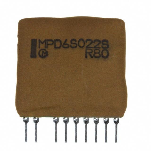
MPD6S022S Application
1
DC-DC Converter Application Manual
MPD6S022S
Features
・ 3.0-5.5V input voltage.
・ High efficiency (95% typ.@3.3V/1A) and small size and floor space saving.
・ Wide output voltage 1.1~3.6V range.
(Output voltage is adjustable.)
・ Input and output voltage capacitor is built in.
・ Short circuit protection is built in.(Latch format)
1. Appearance , Dimensions
9.0max.
21.0max.
MPD6S022S
Body
21.0max.
Overcoat Resin
Possible to expose substrate
Lead
3.0 min.
Impossible to expose electrode
Pin
(0.27)
a 2a a a a a a a
(0.5)
2.7 max.
Pin No. 1 ・ ・ ・ ・ ・ ・ ・ ・ 10
7.4 max.
【Unit:mm】
Expanded Schematic of PinTerminal edge
( )…reference value
Pin Pitch a= 1.8 ±0.3mm
Body
Border Resin
Distance between the both roots of Pin.
Tolerance is not accumulated.
Pin plating
Pin
:SnCu
2. Pin Number and Function
Pin No.
1
2
3
4
5
6,7
8
9,10
Symbol
VIN
ON/OFF
NO PIN
N.C.
N.C
GND
ADJUST
VOUT
Function
Input
Remote ON/OFF
Internal used
Internal used
GND
Output voltage adjustment
Output
GND terminals(Pin No.6 and No.7)should be connected to each other on your substrate in the shortest distance.
VOUT terminals(Pin No.9 and No.10)should be connected to each other on your substrate in the shortest distance.
N.C.(Pin No.4 and No.5)are used in the inside of this product. These pins should not be used in the outside.
Note:
1. This datasheet is downloaded from the website of Murata Manufacturing co., ltd. Therefore, it’ s specifications are subject to change or our
products in it may be discontinued without advance notice. Please check with our sales representatives or product engineers before ordering.
2. This datasheet has only typical specifications because there is no space for detailed specifications. Therefore, please approve our product
specifications or transact the approval sheet for product specifications before ordering.
2008.1.18
�MPD6S022S Application
2
3. Electrical Characteristics (Ta=25 oC)
3.1 Electrical Characteristics (Test condition is specified at item 4.)
Item
Input Voltage
Output Voltage
Condition
Symbol
VIN
VOUT
Typ.
Max.
3.0
5.0
5.5
R1=0Ω
1.067
1.100
1.133
R1=131.5
kΩ±0.5%
3.200
3.300
3.400
-
3.600
-
0.0
-
3.0
A
―
―
100
mV(p -p )
―
95
―
%
0.75
×VIN
―
VIN
0
―
0.25
×VIN
R1=OPEN
Load Current
IOUT
Ripple Voltage
VRIP
Efficiency
EFF1
VIN= 3.0~5.5V
VIN= 5.0V,
VOUT=3.3V,IOUT=3.0A
VIN=5.0V,
VOUT=3.3V,IOUT=1.0A
ON
Remote Voltage
ON/OFF
Unit
Min.
――――――――――――
VIN=3.0~5.5V,
(VIN-VOUT≧1.0V)
Value
VIN= 3.0~5.5V
OFF
V
V
V
OPEN
Internal pull down
resistance of Remote
RON/OFF
Frequency
FREQ.
Protection Circuit
SCP
0≤VON/OFF≤VIN
-
220
-
KΩ
VIN= 3.0~5.5V
―
250
-
kHz
Short-circuit breaking. DC-DC Converter should be recover by opening the
shorted output and RESET Remote.
< Output Voltage Calc.>
VOUT1 = 5.782 / ( 1.606 + 20 / ( 5.479 + R1 ) )
# R1 [kΩ]
3.2 Output Sequence Spec.
DC-DC Converter should be met below Sequence.
t1≥ 0ms , V1=VOUT* + 1.0V
(VOUT* : Set-Up Output Voltage)
VIN
V1
t1
REMOTE
In order to make DC-DC Converter start certainly, please follow the above mentioned sequence.
Note:
1. This datasheet is downloaded from the website of Murata Manufacturing co., ltd. Therefore, it’ s specifications are subject to change or our
products in it may be discontinued without advance notice. Please check with our sales representatives or product engineers before ordering.
2. This datasheet has only typical specifications because there is no space for detailed specifications. Therefore, please approve our product
specifications or transact the approval sheet for product specifications before ordering.
2008.1.18
�MPD6S022S Application
3
4. Test Circuit
IIN
VIN
A
A
1
9,10
V
DCIN
GND
ON/OFF
IOUT
VOUT
A
Vr
V
6
MPD6S022S
7
D1
GND
RL
C1
2
8
ADJUST
R1
V
A
: Digital Multi meter HP34401A equivalent ( Agilent Technologies)
: Ripple Voltmeter
Vr
RM-101 equivalent
( Keisokugiken )
: Electronic Load Device EUL-150αXL equivalent ( Fujitsu access )
RL
: DC Power Supply
HP6621A equivalent ( Agilent Technologies)
C1
: Ceramic Capacitor 0.1μF
D1
: Shottoky Diode
Please do not connect a mass capacitor to the output line of the DC-DC Converter.
※Ripple Noise Test
L
L≦3cm
Ripple Voltmeter or
Oscilloscope
DC-DC
Converter
Load
Keisokugiken RM-101
equivalent
or Tektronix 460A equivalent
Terminating resistance
Output capacitor
Keisokugiken TRC-50F
equivalent
Coaxial cable (1.5D-2V,L=1.5m)
Note:
1. This datasheet is downloaded from the website of Murata Manufacturing co., ltd. Therefore, it’ s specifications are subject to change or our
products in it may be discontinued without advance notice. Please check with our sales representatives or product engineers before ordering.
2. This datasheet has only typical specifications because there is no space for detailed specifications. Therefore, please approve our product
specifications or transact the approval sheet for product specifications before ordering.
2008.1.18
�MPD6S022S Application
4
5. Block Diagram
1
VOUT
Pch
-FET
VIN
9
10
Choke coil
DRIVE
DRIVE
6
ADJUST
Voltage detection circuit
PWM control Circuit
8
Nch
-FET
7
GND
GND
2
ON/OFF
6 Thermal Derating
MPD6S022S Thermal Derating
3.5
3.0
Io(A)
2.5
2.0
1.5
1.0
0.5
0.0
-40
-20
0
20
40
60
80
Ta(℃)
Air Flow=0m/s
Note:
1. This datasheet is downloaded from the website of Murata Manufacturing co., ltd. Therefore, it’ s specifications are subject to change or our
products in it may be discontinued without advance notice. Please check with our sales representatives or product engineers before ordering.
2. This datasheet has only typical specifications because there is no space for detailed specifications. Therefore, please approve our product
specifications or transact the approval sheet for product specifications before ordering.
2008.1.18
�MPD6S022S Application
5
7. Output Voltage Adjustment
・ Resistors connected between Adjust-pin(8pin) to GND-pin (6,7pin) will adjust the output voltage
1.1V ≦ VOUT ≦ 3.3V
・ The following equations give the required external-resistor value to adjust the output voltage to Voadj.
When you change the output voltage, it is necessary to evaluate the characteristics of DC-DC Converter
at your board conditions.
・ If you need VOUT control, keep the input the voltage Vin > Vout + 1.0V.
VOUT =
R1 =
5.782
1.606 + 20/(R1 + 5.479)
20
− 5.479
5.782/VOUT - 1.606
UNIT:[V] [kΩ]
<R1 calculation example>
VOUT [V]
R1 [kΩ]
3.6
Open
3.3
130+1.5
2.5
22+0.82
2.0
10+0.082
Voadj
1.8
1.5
1.2
1.1
R1 [kΩ]
6.8+0.18
3.3+0.12
0.68+0.068
0
8. ON/OFF Control
・ ON/OFF function
The DC-DC Converter can be inactive by using ON/OFF function.
This function is effective when the sequence of a power supply system is constituted.
・ ON/OFF control method
Between ON/OFF-pin(2pin) to VIN-pin(1Pin)
Open……Output Voltage= OFF
Short……Output Voltage= ON
MPD6S022S
2
1
example
Vin
ON/OFF
or
Note:
1. This datasheet is downloaded from the website of Murata Manufacturing co., ltd. Therefore, it’ s specifications are subject to change or our
products in it may be discontinued without advance notice. Please check with our sales representatives or product engineers before ordering.
2. This datasheet has only typical specifications because there is no space for detailed specifications. Therefore, please approve our product
specifications or transact the approval sheet for product specifications before ordering.
2008.1.18
�MPD6S022S Application
6
9. Characteristics Data
Fig.9-1 Efficiency vs Output Current (VIN=5.0V)
100%
95%
Efficiency [%]
90%
85%
80%
75%
70%
65%
60%
0.0
Vo=3.3V
0.5
1.0
1.5
2.0
Vo=2.5V
Vo=1.8V
Output Current [A]
Fig.9.2.1 Output Voltage vs Output Current
2.5
Vo=1.2V
3.0
Fig.9.2.2 Ou
Fig.9-2 Efficiency vs Output Current (VIN=3.3V)
100%
95%
Efficiency [%]
90%
85%
80%
75%
70%
65%
60%
0.0
0.5
1.0
1.5
2.0
2.5
3.0
Vo=1.8V
Vo=1.2V
Output Current
[A]
Note:
1. This datasheet is downloaded from the website of Murata Manufacturing co., ltd. Therefore, it’ s specifications are subject to change or our
products in it may be discontinued without advance notice. Please check with our sales representatives or product engineers before ordering.
2. This datasheet has only typical specifications because there is no space for detailed specifications. Therefore, please approve our product
specifications or transact the approval sheet for product specifications before ordering.
2008.1.18
�MPD6S022S Application
7
10. Packaging Specification
10. 1 Packing form
①The products are putted on the conductive mat in a row as below. (9lines×5pcs.)
Product
Conductive mat
②Above packed products are them piled up three-tier.
Cardboard
Sponge
Product
Conductive mat
Air Cushion
10. 2 Packaging Form
Item
Packaging form typical classification
Dimensions of packaging form
Specification
Box
W = 245 ( mm )
D =
78 ( mm )
H = 104 ( mm )
H
D
W
The number of products in packaging form
Mass of one product
135 ( p c s )
4.3typ. ( g )
Remark
・
If the products have fraction, may not follow this specification.
Note:
1. This datasheet is downloaded from the website of Murata Manufacturing co., ltd. Therefore, it’ s specifications are subject to change or our
products in it may be discontinued without advance notice. Please check with our sales representatives or product engineers before ordering.
2. This datasheet has only typical specifications because there is no space for detailed specifications. Therefore, please approve our product
specifications or transact the approval sheet for product specifications before ordering.
2008.1.18
�MPD6S022S Application
8
11. Soldering
11. 1 Soldering
11.1.1 Flux
Please solder the products with no-cleaning type Rosin Flux which leaves little residue and low activity.
Do not use cleaning type flux, in case that you wash the products afrer using cleaning type flux, they
may damage mounting parts on the products and may cause defective or low quality products.
11. 1.2 Solder
11.1.2.1 Lead Free Solder
Please use the solder Sn-3Ag-0.5Cu.
11.1.2.2 Eutectic Solder
Please use the solder H60, H63 (in JIS Z 3282) or the equivalent type.
11. 1.3 Condition of soldering
11.1.3.1 Lead Free Solder
Please solder under the following condition.
・ Flow soldering Preheating
: 120±10ooC 60~120 seconds
Soldering
: 260±5 C
Time within
: 10 seconds
・ Condition of iron soldering
: under 350 oC, 5 seconds at maximum
(Only iron less than 30W should be used.)
11.1.3.2 Lead Free Solder
・ Flow soldering Preheating
: 120±10 oC 60~120 seconds
o
Soldering
: 230±5 C
Time within
: 5 seconds
・ Condition of iron soldering
: under 300 oC, 3 seconds at maximum
(Only iron less than 30W should be used.)
11. 2 Cleaning
Please do not wash the products.
!
Notice
1. Input / output capacitor
When a inductance or a switch devise are connected to the input line, or when you use a power supply with
output inductance as the input voltage source, the input voltage of the DC-DC Converter will be fluctuated.
By this input voltage fluctuation, the transient load response of the DC-DC Converter may be deteriorated or
abnormal oscillation may occur. So please confirm normal operation on each application.
Please use external input capacitor in order to decrease inductance of input line.
In case you use external output capacitor in order to improve transient load response, please use input
capacitor to prevent abnormal oscillation.
2 Wiring of input / output capacitor
In the case of input / output capacitor connection, in order to reduce electrical noise , please design PCBs
with consideration of the following item.
①. Please be sure to check normal operation on your system.
②. Please use low impedance capacitors with good high frequency characteristic.
③. Please shorten those leads of each capacitor as much as possible, and make sure the lead inductance low.
④. Both input-side and output side, please make the wiring loop between plus and minus as small as possible.
The influence of leakage inductance can be reduced.
⑤. Please design the print pattern of the main circuit as wide and short as possible.. Input / output capacitor
Make wiring roop small
+Vin
+Vout
+Vin
Make wiring roop small
+Vout
DC-DC
Converter
+Vin
Load
GND
-Vin
C1
C2
shorten the leads and pattern
Note:
shorten the leads and pattern
1. This datasheet is downloaded from the website of Murata Manufacturing co., ltd. Therefore, it’ s specifications are subject to change or our
products in it may be discontinued without advance notice. Please check with our sales representatives or product engineers before ordering.
2. This datasheet has only typical specifications because there is no space for detailed specifications. Therefore, please approve our product
specifications or transact the approval sheet for product specifications before ordering.
2008.1.18
�MPD6S022S Application
9
3 This product could not be operated parallel or series.
4 Please do not use a connector or a socket for connection with your board of this product.
Electrical performance may be deteriorated the influence of contact resistance.
Please be sure to mount this product with solder.
5 Be sure to provide an appropriate fail-safe function on your product to prevent a second damage that may be
caused by the abnormal function or the failure of our product.
6 Please connect the input terminal with proper polarity. If you connect wrong polarity, the DC-DC Converter
may be broken. In the case of the DC-DC Converter is damaged, abnormal input current may flow in, and
abnormal overheat of the DC-DC Converter, or some damage of your products may occur. Please use a diode
and a fuse to as following figure.
fuse
diode
+
+
IN
OUT
-
-
Standard of fuse : current rating
5
+
Load
[A]
※Please select diode and fuse after confirming the operation.
!
Note
1. Please contact our main sales office or nearby sales office before using our products for the applications listed
below which require especially high reliability for the prevention of defects which might directly cause damage
to the third party’s life, body or property or this products for any other applications that described in the above.
①Aircraft equipment
②Aerospace equipment
③Undersea equipment
④Power plant control equipment
⑤Medical equipment
⑥Transportation equipment (vehicles, trains, ships, etc.)
⑦Traffic signal equipment
⑧Disaster prevention /crime prevention equipment
⑨Data-processing equipment
⑩Application of similar complexity and/or reliability requirements to the applications listed in the above.
2. This catalog is indicated in May. 2006. About the written contents, since changing without a preliminary
announcement for improvement and supply are sometimes stopped, please confirm in case of ordering.
If the written contents are unknown, please ask to our main sales office or nearby sales office.
3. Types and specification in this catalog are referenced for your information only.
Please confirm detailed specifications by approving our individual drawing and specification sheet.
Note:
1. This datasheet is downloaded from the website of Murata Manufacturing co., ltd. Therefore, it’ s specifications are subject to change or our
products in it may be discontinued without advance notice. Please check with our sales representatives or product engineers before ordering.
2. This datasheet has only typical specifications because there is no space for detailed specifications. Therefore, please approve our product
specifications or transact the approval sheet for product specifications before ordering.
2008.1.18
�


 工商网监
湘ICP备2023018690号
工商网监
湘ICP备2023018690号
