MPDRX104S DATA Sheet
1
DC-DC Converter DATA Sheet
MPDRX104S
1. Features
Ultra high-speed response is realized by using original
ripple detecting control.
Up to 12A output current, non-isolated POL.
Wide adjustable output voltage range by connecting
external resistance (1.5V to 3.3V).o
o
Wide operating temperature(-40 C to +85 C).
UVLO function, ON/OFF function, Output voltage sense function,
Over-current function and Over-temperature function are built in.
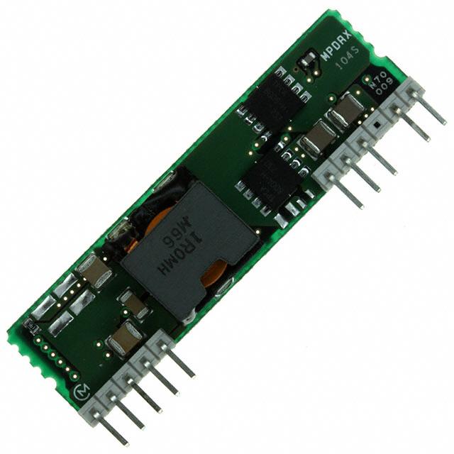
2. Appearance, Dimensions
FrontView
Side View
5.8MAX
50.8
2.7MAX
MPDRX
104S
①②③
14.0
1 2 3 4 5
6 7 8
10 11
4.0±0.4
1.27
2.4±0.4
P P P P
10P
P=2.54mm
Marking
P P
2P
□0.64±0.03
P
unit : mm
Tolerance : 0.25mm
(1) MFG ID
(2) Part No. MPDRX104S
(3) Lot No.
①②③
①Production factory Mark
②Production Year
③Production Month(1,2,3,…9,O,N,D)
Pin Number and Function
Pin No.
Symbol
1,2,4
Vout
3
SENSE
5,6
GND
7,8
Vin
Function
Output terminal of this DC-DC Converter
Output + sense
GND
Input terminal of this DC-DC Converter
10
TRIM
Output voltage adjust terminal. Output voltage can
be adjusted by connecting a resistor between TRIM
pin and GND pin.
11
ON/OFF
Remote ON/OFF terminal. This DC-DC Converter is
shut down when this pin is connected to GND. This
DC-DC Converter operates if this pin left open.
Note:
1. This datasheet is downloaded from the website of Murata Manufacturing co., ltd. Therefore, it’ s specifications are subject to change or our
products in it may be discontinued without advance notice. Please check with our sales representatives or product engineers before ordering.
2. This datasheet has only typical specifications because there is no space for detailed specifications. Therefore, please approve our product
specifications or transact the approval sheet for product specifications before ordering.
2010.12.16
�MPDRX104S DATA Sheet
2
2010.12.16
3. Block Diagram
7,8
Vout
Vin
1,2,4
SENSE
3
5,6
GND
11
ON/OFF
Control Circuit
10
TRIM
4. Environmental Conditions
4 .1 Operating Temperature Range
4 .2 Storage Temperature Range
4 .3 Operating Humidity Range
4 .4 Storage Humidity Range
4 .5 Maximum Wet Bulb
-40 to +85 °C (Temperature gradient ≦10°C /H)
-40 to +85 °C (Temperature gradient ≦25°C /H)
20% ~ 85%(No water condenses in any cases.)
10% ~ 90% (Unpacked condition. No water condenses in any cases.)
39°C
5. Absolute Maximum Rating
5 .1 Input Voltage Range
5 .2 ON/OFF Pin InputVoltage Range
10.8V – 13.2V
-0.3V to Vin+0.3V
Note:
1. This datasheet is downloaded from the website of Murata Manufacturing co., ltd. Therefore, it’ s specifications are subject to change or our
products in it may be discontinued without advance notice. Please check with our sales representatives or product engineers before ordering.
2. This datasheet has only typical specifications because there is no space for detailed specifications. Therefore, please approve our product
specifications or transact the approval sheet for product specifications before ordering.
2010.12.16
エ
ラ
ー
!
連
番
が
指
定
さ
れ
て
い
ま
せ
ん
。
�MPDRX104S DATA Sheet
3
2010.12.16
6. Characteristics
o
6.1 Electrical Characteristics (Ta=25 C)
Value
Item
Condition
Unit
Symbol
Min.
Typ.
Max.
Input Voltage Range
Vin
10.8
-
13.2
V
Rising UVLO Threshold
UVLO
Vin Increasing
9.3
10.0
10.8
V
Falling UVLO Threshold
UVLOf
Vin Decreasing
9.0
9.5
10.3
V
Output Voltage
Adjustable Range
Vout
ON/OFF= Open
1.5
-
3.3
V
Output Current
Iout
See the thermal derating curve
in clause 6.2.
0
-
12
A
Output Voltage Accuracy
Vo tol
Over Vin, Io, temperature range
Rset=0.5% tolerance
-3
-
+3
%Vo
Ripple Voltage
Vrpl
Ttr
Transient Response
ΔVtr
Efficiency
EFF
Operating Frequency
Frq
ON/OFF pin High Voltage
VIH
ON/OFF pin Low Voltage
VIL
Short Circuit Protection
SCP
Over Temperature
Protection
External Output Capacitor
Vin=12V,
Iout=12ABW=20MHz,
Cout=100μF
Vout=3.3V
-
15
-
Vout=1.5V,
-
25
-
Vin=12V, Vout=1.8V
Iout=6⇔12A,
di/dt=2A/μs,
Cout=100μF
Recovery Time
-
30
-
μsec
Vout Deviation
-
50
-
mV
Vin =12.0V, Vout=3.3V, Iout=12A
-
88
-
%
Vin =12.0V, Vout=3.3V
-
600
-
Vin =12.0V, Vout=1.5V
-
300
-
mV(p_p)
kHz
ON/OFF pin is pulled up to Vin inside of the DC-DC Converter. If ON/OFF pin is left open,
the DC-DC Converter shall be “ON”. This pin will be pulled down to GND inside the DC-DC
Converter when OCP or OTP events occur. Please do NOT connect this pin to Vin with low
impedance line, so as not to damage the converter..
Vin-0.3
-
0.7
V
Reset, Followed by Auto-Recovery
13
19
-
A
OTP
Reset, Followed by Auto-Recovery
-
115
-
Cout
When input voltage is ideal voltage
source
47
100
1000
o
C
μF
※Caution
The above electrical characteristics are guaranteed with the condition that the impedance of the input voltage
source is sufficiently low as shown in section 9. Connecting an input inductance or using an input power supply
with output inductance may cause an unstable operation of this device. Please check the proper operation of this
device with the peripheral circuits on your system.
Note:
1. This datasheet is downloaded from the website of Murata Manufacturing co., ltd. Therefore, it’ s specifications are subject to change or our
products in it may be discontinued without advance notice. Please check with our sales representatives or product engineers before ordering.
2. This datasheet has only typical specifications because there is no space for detailed specifications. Therefore, please approve our product
specifications or transact the approval sheet for product specifications before ordering.
2010.12.16
エ
ラ
ー
!
連
番
が
指
定
さ
れ
て
い
ま
せ
ん
。
�MPDRX104S DATA Sheet
4
2010.12.16
6.2 Thermal Derating
MPDRX104S Thermal Derating
[ Vin=12V , Vout=2.5V ]
18
16
Output Current [A]
14
12
10
8
6
4
2
0
0
10
20
30
40
50
60
70
80
90
80
90
Ta [℃]
0m/s
0.5m/s
1.0m/s
2.0m/s
MPDRX104S Thermal Derating
[ Vin=12V , Vout=3.3V ]
18
16
Output Current [A]
14
12
10
8
6
4
2
0
0
10
20
30
40
50
60
70
Ta [℃]
0m/s
0.5m/s
1.0m/s
2.0m/s
The above derating limits apply to this product soldered directly to 101.6*180mm*1.6mm PCB (double-sided,
with 70um copper). Any adjacent parts of high temperature may cause overheating. For reliable operation,
please ensure that the FET temperature of this product is maintained below 120°C and the inductor t
emperature is below 106°C.
Note:
1. This datasheet is downloaded from the website of Murata Manufacturing co., ltd. Therefore, it’ s specifications are subject to change or our
products in it may be discontinued without advance notice. Please check with our sales representatives or product engineers before ordering.
2. This datasheet has only typical specifications because there is no space for detailed specifications. Therefore, please approve our product
specifications or transact the approval sheet for product specifications before ordering.
2010.12.16
エ
ラ
ー
!
連
番
が
指
定
さ
れ
て
い
ま
せ
ん
。
�MPDRX104S DATA Sheet
5
2010.12.16
7. Operation in information
7.1 Adjusting the Output Voltage
The output voltage can be adjusted ranging from 1.5V to 3.3V by connecting resistors between TRIM-pin
(10Pin) to GND-pin (5Pin).
The following equation gives the required external-resistance value to adjust the output voltage to the
required Vout.
Internal circuit
MPDRX104S
Vout
R trim =
12k Ω
TRIM pin
Rtrim
11280
Vo ut - 1.5
- 5100
[ohm]
5.1k Ω
Error amp
20k Ω
<Rtrim calculation example>
Vout [V]
Calculated Rtrim[Ω]
Applied Rtrim (example) [Ω]
3.3
1.17k
1.0k+160
2.5
6.18k
5.6k+560
2.0
17.5k
16k+1.5k
1.8
32.5k
30k+2.4k
1.5
∞
Open
7.2 ON/OFF Control
ON/OFF function
By using ON/OFF function, the operation of this product can be disabled without disconnection of input
voltage. Sequence of a power supply system and power-saving control can be easily achieved using
this function.
ON/OFF control usage
When ON/OFF-pins(11pin) are left open
When ON/OFF-pins(11pin) are connected to GND
……
……
Output Voltage =ON
Output Voltage=OFF
MPDRX104S
11
5,6
example
GND
on/off
or
Note:
1. This datasheet is downloaded from the website of Murata Manufacturing co., ltd. Therefore, it’ s specifications are subject to change or our
products in it may be discontinued without advance notice. Please check with our sales representatives or product engineers before ordering.
2. This datasheet has only typical specifications because there is no space for detailed specifications. Therefore, please approve our product
specifications or transact the approval sheet for product specifications before ordering.
2010.12.16
エ
ラ
ー
!
連
番
が
指
定
さ
れ
て
い
ま
せ
ん
。
�MPDRX104S DATA Sheet
6
7.3 Output Voltage Sensing
By connecting SENSE-pin to the load, output voltage drop in wiring shall be compensated.
Vout
MPDRX104S
SENSE
Load
GND
Please do NOT connect SENSE-pin to the output of LC filter that is set to the Vout line.
When using this way, this product will not operate properly.
Vout
MPDRX104S
SENSE
Load
GND
7.4 Input External capacitor
It is recommended to connect a ceramic capacitor or a low-impedance electrolytic capacitor of 22μF or more
at Vin terminal. Smaller input capacitor may leads to an unstable operation of this product caused by input
voltage fluctuation.
Please check the proper operation of it on your product when smaller input capacitor is used.
7.5 Output External capacitor
Ceramic capacitors are recommended as output external capacitor.
Using ceramic capacitors, small output variation and small ripple voltage are realized.
Output capacitor should be within 47μF to 1000μF. Output capacitor shall be placed near the output terminal.
When using plural capacitors, please make sure to place a capacitor of at least 47μF near the output terminal,
and place other capacitors near the load.
When using LC output filter, please make sure to place a capacitor of at least 47μF near the output terminal.
8. Reliability
8.1 Humidity
According to JIS-C-0022.
40 土2°C, 90 to 95%RH, 100 hours. Leave for 4 hours at room temperature.
No damage in appearance and no deviation from electrical characteristics (section 6.1.).
8.2 Temperature Cycles
Repeat cycle 5 times. Leave 2 hours at room temp.
No damage in appearance and no deviation from electrical characteristics (section 6.1.).
Step
Condition
Time
1
-40°C±3°C˚C
30 minutes
2
Room Temp.
5-10 minutes
3
+85°C±2°C
30 minutes
4
Room Temp.
5-10 minutes
8.3 Vibration
10 to 55Hz, 1.5mm amplitude (1minute cycle), 1 hour for each of X, Y, Z directions.
No damage in appearance and no deviation from electrical characteristics (section 6.1.).
8.4 Mechanical Shock
20G, 1 time for each X, Y, Z directions.
No damage in appearance and no deviation from electrical characteristics (section 6.1.).
Note:
1. This datasheet is downloaded from the website of Murata Manufacturing co., ltd. Therefore, it’ s specifications are subject to change or our
products in it may be discontinued without advance notice. Please check with our sales representatives or product engineers before ordering.
2. This datasheet has only typical specifications because there is no space for detailed specifications. Therefore, please approve our product
specifications or transact the approval sheet for product specifications before ordering.
エ
ラ
ー
!
連
番
が
指
定
さ
れ
て
い
ま
せ
ん
。
2010.12.16
�MPDRX104S DATA Sheet
7
2010.12.16
9. Test Circuit
In the following test circuit, the initial values under item 6.1. should be met.
Vout
Vin
1,2,4
7,8
SENSE
+
Vin
MPDRX104S
3
RL
ON/OFF
Cin: 100μF
TRIM
Rset
5,6
GND
Open=ON
Short=OFF
Cin
:
Cout :
Cout: 100μF
10
11
100uF/16V (16ZL120MMRKTA6.3X11,Rubycon)
(Low-impedance Electrolytic Capacitor)
100uF/6.3V (GRM32EB30J107ME16L, Murata)
(Ceramic Capacitor)
9.2. Ripple Voltage Measurement Circuit
Cout:100uF
Coaxial cable :1.5D-2V, L=1.5m
Oscilloscope
BW:20MHz
Vout
DC-DC Converter
GND
Terminator
(Keisokugiken TRC-50F)
Equivalent circuit
R:50Ω
C:0.01uF
A
A:Output Ripple Voltage
Note:
1. This datasheet is downloaded from the website of Murata Manufacturing co., ltd. Therefore, it’ s specifications are subject to change or our
products in it may be discontinued without advance notice. Please check with our sales representatives or product engineers before ordering.
2. This datasheet has only typical specifications because there is no space for detailed specifications. Therefore, please approve our product
specifications or transact the approval sheet for product specifications before ordering.
2010.12.16
エ
ラ
ー
!
連
番
が
指
定
さ
れ
て
い
ま
せ
ん
。
�MPDRX104S DATA Sheet
8
10. Packaging Specification
①Like the figure below, put the product on the conductive mat in a row. (5lines×4columns)
②Pile and pack the 3 above–mentioned units at maximum.
4 columns
Conductive mat
Product
5 lines
Fig1-1. Top View
Corrugated Paper
Sponge
Product
Conductive Mat
Cushion
Corrugated Paper
Fig1-2.Side View
Note:
1. This datasheet is downloaded from the website of Murata Manufacturing co., ltd. Therefore, it’ s specifications are subject to change or our
products in it may be discontinued without advance notice. Please check with our sales representatives or product engineers before ordering.
2. This datasheet has only typical specifications because there is no space for detailed specifications. Therefore, please approve our product
specifications or transact the approval sheet for product specifications before ordering.
エ
ラ
ー
!
連
番
が
指
定
さ
れ
て
い
ま
せ
ん
。
2010.12.16
�MPDRX104S DATA Sheet
9
Corrugated Box
Note:
1. This datasheet is downloaded from the website of Murata Manufacturing co., ltd. Therefore, it’ s specifications are subject to change or our
products in it may be discontinued without advance notice. Please check with our sales representatives or product engineers before ordering.
2. This datasheet has only typical specifications because there is no space for detailed specifications. Therefore, please approve our product
specifications or transact the approval sheet for product specifications before ordering.
エ
ラ
ー
!
連
番
が
指
定
さ
れ
て
い
ま
せ
ん
。
2010.12.16
�MPDRX104S DATA Sheet
10
Item
Specification
Packaging form typical classification
Box
Dimensions of packaging form(typ.)
W = 245 ( mm )
D =
78 ( mm )
H = 104 ( mm )
H
D
W
The number of products in packaging form
60
( pcs )
Mass of one product
5
(g)
Remark
・The number of the product in one box may be less than 60, if needed.
※On the packing box, the following is indicated.
Murata Part No.
Quantity
Stamp No.
11. Production factory
Komatsu Murata Mfg.Co.,Ltd.
Kanazu Murata Mfg.Co.,Ltd.
Wakura Murata Mfg. Co., Ltd.
Note:
1. This datasheet is downloaded from the website of Murata Manufacturing co., ltd. Therefore, it’ s specifications are subject to change or our
products in it may be discontinued without advance notice. Please check with our sales representatives or product engineers before ordering.
2. This datasheet has only typical specifications because there is no space for detailed specifications. Therefore, please approve our product
specifications or transact the approval sheet for product specifications before ordering.
エ
ラ
ー
!
連
番
が
指
定
さ
れ
て
い
ま
せ
ん
。
2010.12.16
�MPDRX104S DATA Sheet
11
12. Typical Characteristics Data
12.1 Load Transient Response
Our original ripple-detective control method achieves better load transient responses.
Vin=12V, Vo=3.3V, Io=6A ->12A, di/dt=2A/μs, Cout=100μF(Ceramic)
Io(4A/div)
Io(3A/div)
Vo(50mV/div)
Vo(50mV/div)
10μs/div
Fig. 12-1. Load Transient Response
12.2 Output Impedance characteristics
Our original ripple-detective control method achieves very low output impedance in wide frequency range.
(Fig. 12 shows the output impedance characteristics of MPDRX003S, which uses the same control method)
MPDRX003S Output Impedance
Vo=1.8V, Io=612A
Conventional PMW Product's Output
Impedance
Io=4.5A 6.0A
100
100
80
Zo [mohm]
Zo [mohm]
80
60
40
40
20
20
0
0.01
60
0.1
1
10
100
Frequency [kHz]
Fig. 12.2.1 Output Impedance of MPDRX003S
0
0.01
0.1
1
10
100
Frequency [kHz]
Fig. 12.2.2 Output Impedance of conventional product
Note:
1. This datasheet is downloaded from the website of Murata Manufacturing co., ltd. Therefore, it’ s specifications are subject to change or our
products in it may be discontinued without advance notice. Please check with our sales representatives or product engineers before ordering.
2. This datasheet has only typical specifications because there is no space for detailed specifications. Therefore, please approve our product
specifications or transact the approval sheet for product specifications before ordering.
エ
ラ
ー
!
連
番
が
指
定
さ
れ
て
い
ま
せ
ん
。
2010.12.16
�MPDRX104S DATA Sheet
12
2010.12.16
12.3 Other electrical characteristics
12.3.1 Vout=3.3V
(Ta=25°C,Cin= 100μF Low-impedance Electrolytic Capacitor,Cout=GRM32EB30J107ME16L,Rtrim=1.17Ω)
92
3.320
90
88
3.310
Efficiency (%)
Output Voltage(V)
3.315
3.305
3.300
86
84
82
80
3.295
78
3.290
76
0
2
4
6
8
10
12
0
2
Io(A)
Vin=10.8V
Vin=12.0V
4
6
8
10
12
Io(A)
Vin=13.2V
Fig. 12.3.1 Output Voltage v.s. Output Current
Vin=10.8V
Vin=12.0V
Vin=13.2V
Fig. 12.3.2 Efficiency v.s. Output Current
30
Ripple Voltage (V)
25
20
15
10
5
0
0
2
4
6
8
10
12
Io(A)
Vin=10.8V
Vin=12.0V
Vin=13.2V
Fig. 12.3.3 Ripple Voltage v.s. Output Current
Note:
1. This datasheet is downloaded from the website of Murata Manufacturing co., ltd. Therefore, it’ s specifications are subject to change or our
products in it may be discontinued without advance notice. Please check with our sales representatives or product engineers before ordering.
2. This datasheet has only typical specifications because there is no space for detailed specifications. Therefore, please approve our product
specifications or transact the approval sheet for product specifications before ordering.
2010.12.16
エ
ラ
ー
!
連
番
が
指
定
さ
れ
て
い
ま
せ
ん
。
�MPDRX104S DATA Sheet
13
2010.12.16
2.530
92
2.525
90
2.520
88
Efficiency (%)
Output Voltage(V)
12.3.2 Vout=2.5V
(Ta=25°C,Cin= 100μF Low-impedance Electrolytic Capacitor,Cout=GRM32EB30J107ME16L,Rtrim=6.18kΩ)
2.515
2.510
2.505
86
84
82
2.500
80
2.495
78
2.490
76
0
2
4
6
8
10
12
0
2
6
8
10
12
Io(A)
Io(A)
Vin=10.8V
4
Vin=12.0V
Vin=13.2V
Fig. 12.3.4 Output Voltage v.s. Output Current
Vin=10.8V
Vin=12.0V
Vin=13.2V
Fig. 12.3.5 Efficiency v.s. Output Current
30
Ripple Voltage (V)
25
20
15
10
5
0
0
2
4
6
8
10
12
Io(A)
Vin=10.8V
Vin=12.0V
Vin=13.2V
Fig. 12.3.6 Ripple Voltage v.s. Output Current
Note:
1. This datasheet is downloaded from the website of Murata Manufacturing co., ltd. Therefore, it’ s specifications are subject to change or our
products in it may be discontinued without advance notice. Please check with our sales representatives or product engineers before ordering.
2. This datasheet has only typical specifications because there is no space for detailed specifications. Therefore, please approve our product
specifications or transact the approval sheet for product specifications before ordering.
2010.12.16
エ
ラ
ー
!
連
番
が
指
定
さ
れ
て
い
ま
せ
ん
。
�MPDRX104S DATA Sheet
14
2010.12.16
13. Mounting Condition
13.1 Recommendable Solder Land Pattern
Pin Size
Hole diameter
Land diameter
0.64mm
φ0.9mm
φ2.0mm
As for the position of holes, refer to the appearance figure.
13.2 Solder
13.2.1 Solder
Lead Free Solder
Please use the solder Sn-3Ag-0.5Cu.
13.2.2 Eutectic Solder
Please use the solder H60, H63 (in JIS Z 3282) or the equivalent type .
13.3 Recommended Soldering Conditions
13.3.1 Lead Free Solder
Please solder under the following condition :
Flow soldering Preheating
:120±10°C 60~120 seconds
Soldering
:260°C +0°C /-5°C
Time
:not more than 10seconds
Condition of iron soldering
:350°C MAX, 3 seconds at maximum
(Soldering iron of less than 30W should be used.)
13.3.2 Eutectic Solder
Please solder under the following condition :
Flow soldering Preheating
:120±10°C 60~120 seconds
Soldering
:230°C +0°C /-5°C
Time
:not more than 10 seconds
Condition of iron soldering
:300°C MAX, 3 seconds at maximum
(Soldering iron of less than 30W should be used.)
14. Notice
14. 1 Both input-side and output side, please make the wiring loop between plus and minus as small as possible.
The influence of a leakage inductance can be reduced.
14. 2 Please make the power line pattern as wide and short as possible.
The Following figure is an example of recommendable PCB design.
Product
Lead
Vout
GND
Vin
Output capacitor
Input capacitor
Top View
14. 3 This product should not be operated in parallel nor in series.
14. 4 Please do not use a connector or a socket to connect this product to your product.
The electric characteristics may be deteriorated by the influence of contact resistance.
Note:
1. This datasheet is downloaded from the website of Murata Manufacturing co., ltd. Therefore, it’ s specifications are subject to change or our
products in it may be discontinued without advance notice. Please check with our sales representatives or product engineers before ordering.
2. This datasheet has only typical specifications because there is no space for detailed specifications. Therefore, please approve our product
specifications or transact the approval sheet for product specifications before ordering.
2010.12.16
エ
ラ
ー
!
連
番
が
指
定
さ
れ
て
い
ま
せ
ん
。
�MPDRX104S DATA Sheet
15
2010.12.16
14. 5 Be sure to provide an appropriate fail-safe function on your product to prevent secondary damage that may be
caused by the functional trouble or the failure of this product.
14. 6 Inrush current protection is not a feature of this product.
14. 7 Please connect the input terminals with the correct polarity. If an error in polarity connection is made this
product may be damaged. If this product is damaged internally, an elevated input current may flow, and so this
product may exhibit an abnormal temperature rise, or your product may be damaged.
Please add a diode and fuse per the following diagram to protect them.
fuse
diode
+
+
IN
OUT
-
-
+
Load
※Please select diode and fuse after confirming the operation of your product.
14. 8 Cleaning
14.8.1Please clean the products to remove flux from them using the dipping, and vapor methods in isopropyl
alcohol for up to 5 minutes.
Please inform us if you are to use aqueous or semi-aqueous cleaning or another methods.
Do not use ultrasonic cleaning as semiconductor devices on the products, may be damaged
by resonance.
14.8.2 After cleaning, please dry the products thoroughly. If you touch the products that have not been dried
enough, you must take care because the products markings may thin or blur.
Do not measure electrical characteristics, until the products are completely dry.
14. 9 Storage
14.9.1 Please avoid dampness and heat or locations where temperatures may vary widely to avoid
Possible water condensation on the product. Exposure to such environments may degrade the
performance and/or the reliability of the product.
If the product must be stored for a longer time than 1 year it is recommend that solderability be
tested regularly to confirm material degradation has not occurred.
14. 10 Please do not store the products in the places such as in a dusty place, in a place exposed directly to sea
breeze, in an atmosphere containing corrosive gas (Cl2,NH3,SO2,NOX and so on).
Note:
1. This datasheet is downloaded from the website of Murata Manufacturing co., ltd. Therefore, it’ s specifications are subject to change or our
products in it may be discontinued without advance notice. Please check with our sales representatives or product engineers before ordering.
2. This datasheet has only typical specifications because there is no space for detailed specifications. Therefore, please approve our product
specifications or transact the approval sheet for product specifications before ordering.
2010.12.16
エ
ラ
ー
!
連
番
が
指
定
さ
れ
て
い
ま
せ
ん
。
�MPDRX104S DATA Sheet
16
14. 11 Operational Environment and Operational Conditions
14.11.1 Operational Environment
The products are not waterproof, chemical-proof or rust-proof.
In order to prevent leakage of electricity and abnormal temperature increase of the products, do not use the
products under the following circumstances:
(1) in an atmosphere containing corrosive gas (Cl2, NH3, SO2, NOX and so on).
(2) in a dusty place.
(3) in a place exposed to direct sunlight.
(4) in such a place where water splashes or in such a humid place where water condenses.
(5) in a place exposed to sea breeze.
(6) in any other places similar to the above (1)through (5).
14.11.2 Operational Conditions
Please use the products within specified values (power supply, temperature, input, output and load condition,
and so on). Input voltage drop for line impedance, so please make sure that input voltage is included in
specified values.
If you use the products over the specified values, it may break the products, reduce the quality, and even if the
products can endure the condition for short time, it may cause degradation of the reliability.
Also please take care that the external voltage over output voltage of DC-DC Converter does not applies to
output of this DC-DC Converter.
14.11.3 Note prior to use
If you apply high static electricity, over rated voltage or reverse voltage to the products, it may cause defects in
the products or degrade the reliability.
Please avoid the following items:
(1) over rating power supply, reverse power supply or not-enough connection of 0 V(DC) line.
(2) electrostatic discharge by production line and/or operator.
(3) electrified product by electrostatic induction.
Do not give an excessive mechanical shock..
If you drop the products on the floor, etc., it may occur a crack to the core of inductors and monolithic ceramic
capacitors.
Do not give a strong shock such as a drop in handling.
14. 12 Transportation
If you transport the products, please pack them so that the package will not be damaged by mechanical
vibration or mechanical shock, and please educate and guide a carrier to prevent rough handling.
If you transport the products to overseas (in particular, by sea), it is expected that the transportation
environment will be the worst, so please pack the products, in the package designed on the consideration of
mechanical strength, vibration-resistant and humidity-resistant. The package of the products which Murata
sells in Japan, may not resist over seas transport.
Please consult us if you are to use the Murata package of the products sold in Japan for transport to overseas.
!
Note
1. Murata recommends that customers ensure that the evaluation and testing of these devices are completed
withthis product actually assembled on their product.
2. Please contact our main sales office or nearby sales office before using our products for the applications listed
below which require especially high reliability for the prevention of defects which might directly
cause damage to the third party’s life, body or property or this products for any other applications that
described in the above.
①Aircraft equipment
②Aerospace equipment
③Undersea equipment
④Power plant control equipment
⑤Medical equipment
⑥Transportation equipment (vehicles, trains, ships, etc.)
⑦Traffic signal equipment
⑧Disaster prevention /crime prevention equipment
⑨Data-processing equipment
⑩Application of similar complexity and/or reliability requirements to the applications listed in the above.
This DATA Sheet is indicated in Apr. 2006. About the written contents, since changing without a preliminary
announcement for improvement and supply are sometimes stopped, please confirm in case of ordering.
If written contents are unknown, please ask to our main sales office or nearby sales office.
Note:
1. This datasheet is downloaded from the website of Murata Manufacturing co., ltd. Therefore, it’ s specifications are subject to change or our
products in it may be discontinued without advance notice. Please check with our sales representatives or product engineers before ordering.
2. This datasheet has only typical specifications because there is no space for detailed specifications. Therefore, please approve our product
specifications or transact the approval sheet for product specifications before ordering.
エ
ラ
ー
!
連
番
が
指
定
さ
れ
て
い
ま
せ
ん
。
2010.12.16
�


 工商网监
湘ICP备2023018690号
工商网监
湘ICP备2023018690号
