MP MOTION SENSOR
2002.10.23 7:56 PM
Page 2
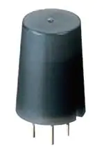
MP Motion Sensor (AMN1)
MP MOTION
SENSOR
‘
’
MOTION SENSOR
(PASSIVE INFRARED TYPE)
NaPiOn web page URL:
http://www.napion.com/
FEATURES
Standard type
Slight motion
detection type
1. The world’s smallest with a built-in
amplifier
Extremely compact. Ideal for use in
miniaturized devices.
2. Dual lens colors (white and black)
are provided
With an ultrasmall design and dual lens
colors (white and black), it is inconspicuous, allowing the user to select either
white or black to match the equipment
color. This provides greater flexibility in
equipment design.
3. Both digital output and analog output (with adjustable sensitivity) are
available.
4. Built-in amplifier for easy use
Has a built-in amplifier, and can be connected directly to a microcomputer.
5. Detects even slight motion of a person
With our sensor, even slight motions
made by people will be detected easily.
• Fine motion detection capability within
approximately 2 meters of sensor.
Standard type:
Detects movement of approximately
30cm 11.811inch.
Slight motion detection type:
Detects movement of approximately
20cm 7.874inch.
6. Noise withstanding capability
Circuitry is contained in a TO5 metal
package, providing at least twice the
noise withstanding capability as conventional type.
• Comparison example of noise withstanding capability
• Block diagram of the digital output circuit
TO5 metal package
(9.8mm × 9mm .386inch × .354inch dia.)
Spot type
10 m detection type
Infrared
radiation
What is passive infrared type?
This sensor detects changes in infrared radiation which
occur when there is movement by a person (or object)
which is different in temperature from the surroundings.
Q As this sensor detects temperature differences, it is
well suited to detecting the motion of people by their
body temperature.
W Wide sensing area.
Single-chip
Stabilized
IC
power
supply
Amplifier
circuit
Multi lens
Optical filter
Comparator
output
circuit
Vdd
Output
APPLICATIONS
Gnd
1. Home appliances
Quad type
PIR element
• Block diagram of the analog output circuit
Sensor
TO5 metal package
(9.8mm × 9mm .386inch × .354inch dia.)
Infrared
radiation
Temperature difference
Infrared
radiation
Infrared
radiation
Movement
Multi lens
Optical filter
Single-chip
Stabilized
IC
power
supply
Gnd
Quad type
PIR element
ORDERING INFORMATION
Output
1: Digital output
2: Analog output
Detection performance
1: Standard detection type
2: Slight motion detection type
3: Spot detection type
4: 10m detection type
Feature
1: PC board mounting type
Operating voltage
1: 5V DC
Lens color
1: Black
2: White
2
AMN
1
Useful for saving energy in air conditioner,
television, personal computer, or ventilator
and air purifier
2. Amusement machine market
Useful for saving energy and for automated
guidance in theme parks and large video
games
3. Equipment in service market
Vdd
Output
Amplifier
circuit
Conventional type
MP Motion Sensor
Distance at which motion
sensor is not affected
by cellular phone noise
Min. 1 to 2m 3.281 to 6.562ft
Min. 1 to 2cm .394 to .787inch
1
Useful for automated guidance, automated
announcements and energy saving in vending
machines, ATMs, etc.
4. Lighting market
Automated on/off controls, etc. for lamps,
desk lamps, indoor lights, halls, stairway
lights, etc.
�MP MOTION SENSOR
2002.10.23 7:56 PM
Page 3
MP Motion Sensor (AMN1)
PRODUCT TYPES
1. Digital output
Rated operating voltage
Detection performance
Ambient temperature
Lens color
Part No.
–20 to +60°C –4 to +140°F
Black
White
Black
White
Black
White
Black
White
AMN11111
AMN11112
AMN12111
AMN12112
AMN13111
AMN13112
AMN14111
AMN14112
Ambient temperature
Lens color
Part No.
–20 to +60°C –4 to +140°F
Black
White
Black
White
Black
White
Black
White
AMN21111
AMN21112
AMN22111
AMN22112
AMN23111
AMN23112
AMN24111
AMN24112
Standard detection type
Slight motion
detection type
3 to 6 V DC
Spot detection type
10m detection type
Packing quantity
Inner
Outer
50 pcs.
1,000 pcs.
2. Analog output
Rated operating voltage
Detection performance
Standard detection type
Slight motion
detection type
4.5 to 5.5 V DC
Spot detection type
10m detection type
Packing quantity
Inner
Outer
50 pcs.
1,000 pcs.
PERFORMANCE
1. Detection performance
Standard
detection type
Items
Rated detection
distance*Remark 1
Slight motion
detection type
Spot detection
type
10m detection
type
5m 16.404ft
(Max.)
2m 6.562ft
(Max.)
5m 16.404ft
(Max.)
10m 32.808ft
(Max.)
100°
82°
64 zones
91°
91°
104 zones
38°
22°
24 zones
110°
93°
80 zones
Horizontal*Remark 2
Detection
Vertical*Remark 2
range
Detection zone*Remark 3
2.
Conditions of objects to be detected
1. Detectable difference in temperature between the target
and background for the spot type is more than 4°C 39.2°F.
2. Movement speed
• Standard detection type/Spot detection type/
10m detection type: 1.0 m/s
• Slight motion detection type: 0.5 m/s
3. Detection object = human body (size is 700mm × 250mm
27.559inch × 9.843inch, but for the slight motion detection
type the size is 200mm × 200mm 7.874inch × 7.874inch)
*Remarks1. Depending on the difference in temperature between the
background and detection target and the speed at which the
target moves, these sensors may be capable of detection
Horizontal
beyond the detection distances stated above. Nevertheless,
they should be used within the prescribed detection distances.
Cut out
For further details, refer to the detection range diagram on
page 5.
3. Regarding of detection zone, please refer to “DETECTION
(Spot detection type/
PERFORMANCE” on page 5.
10 m detection type)
Vertical
Vertical
Horizontal
Cut out
(Standard detection/
Slight motion detection type)
2. Rating (Measuring condition: ambient temp. = 25°C 77°F) (Common to All types)
Items
Power supply voltage
Usable ambient temperature
Storage temperature
Specified value
–0.3 to 7 V DC
–20 to 60°C –4 to +140°F
–20 to 70°C –4 to +158°F
Remarks
No freezing and condensing at low temperature.
3. Electrical characteristics (Measuring condition: ambient temp. = 25°C 77°F; operating voltage = 5V) (Common to All types)
1) Digital output
Items
Reted operating voltage
Reted consumption current
(Standby) *Remark
Output
(when detecting)
Circuit stability time
Current
Voltage
Symbol
Minimum
Typical
Maximum
Typical
Maximum
Maximum
Minimum
Maximum
Typical
Maximum
Vdd
Iw
Iout
Vout
Twu
Specified value
3.0 V DC
—
6.0 V DC
170 µA
300 µA
100 µA
Vdd –0.5
Vdd (Same as operating voltage)
7s
30 s
Measured conditions
Iout = 0
Vout 7 Vdd–0.5
Open when not detecting
Remark: The current which is consumed during detection consists of the standby consumed current plus the output current.
3
�MP MOTION SENSOR
2002.10.23 7:56 PM
Page 4
MP Motion Sensor (AMN1)
2) Analog output
Items
Symbol
Minimum
Maximum
Reted operating voltage
Reted consumption current
Output current
Output voltage
Output offset average voltage
Steady-state noise
Circuit stability time
Specified value
4.5 V DC
5.5 V DC
Vdd
Typical
Maximum
Maximum
Minimum
Typical
Maximum
Minimum
Typical
Maximum
Typical
Maximum
Maximum
0.17 mA
0.3 mA
50 µA
0V
2.5 V
Vdd
2.3 V
2.5 V
2.7 V
130 m Vp-p
300 m Vp-p
45 s
Iw
Iout
Vout
Voff
Vn
Twu
Measured conditions
Iout = 0
Steady-state output
voltage when not
detecting
Note: To set to the same detection performance as the digital type, set the output voltage to the offset voltage (2.5V) ±0.45V (i.e. 2.95V or more and 2.05V or less).
[Timing chart]
1) Digital output
ON
Power supply
OFF
Detect
Detection state
Not
detect
ON
Sensor output
OFF
Circuit stability time
Remark: Circuit stability time: 45s max.
While the circuitry is stabilizing after the power is turned on, the sensor output is not fixed in the “on” state or “off” state. This is true regardless of whether or not
the sensor has detected anything.
2) Analog output
Vdd
Power supply
GND
Detect
Detection state
(Comparator
decision output)
Output waveform
V out
Not
detect
Body
movement
Vdd
Voff
Vh
Threshold voltage 1
(comparator)
Vn
GND
Vl
Circuit stability time
Threshold voltage 2
(comparator)
Remark: Circuit stability time: 30s max.
While the circuitry is stabilizing after the power is turned on, the sensor output is not fixed in the “on” state or “off” state. This is true regardless of whether or not
the sensor has detected anything.
4
�MP MOTION SENSOR
2002.10.23 7:56 PM
Page 5
MP Motion Sensor (AMN1)
DETECTION PERFORMANCE
1. Standard detection type
TOP VIEW
5m
16.404ft
SIDE VIEW
5m
16.404ft
X
50°
Y
41°
2.5m
8.202ft
2.5m
8.202ft
0°
0°
2.5m
8.202ft
2.5m
8.202ft
41°
50°
5m
16.404ft
5m
16.404ft
X-Y cross section
Y
3m
9.843ft
Detection zone
2
6.562
1
3.281
4m
3
13.123ft 9.843
2
6.562
1
3.281
1
3.281
2
6.562
1
3.281
(Max. 5.66m)
(Max. 18.570ft)
X
3
4m
9.843 13.123ft
Remarks: 1. The X-Y cross-sectional diagram shows the detection area.
2. The differences in the detection zone patterns are indicative of the projections of the 16 lenses with single focal point and with five optical axes. An
object whose temperature differs from the background temperature and
which crosses inside the detection zone will be detected.
2
6.562
3m
9.843ft
(Max. 7.42m)
(Max. 24.344ft)
2. Slight motion detection type
X-Y cross
section
Y
2.5m
8.202ft
Y
2.5m
8.202ft
2
6.562
46°
2
6.562
1.5
4.921
1.5
4.921
1
3.281
1
3.281
0.5
1.640
0.5
1.640
0
1m
3.281ft
2m
6.562ft
0°
–2.5m
–8.202ft
–2
–1.5
–1
–0.5
–6.562 –4.921 –3.281 –1.640
–0.5
–1.640
–0.5
–1.640
–1
–3.281
–1
–3.281
–1.5
–4.921
–1.5
–4.921
–2
–6.562
–2
–6.562
–2.5m
–8.202ft
Detection zone
46°
1m
3.281ft
2m
6.562ft
0.5
1
1.5
2
1.640 3.281 4.921 6.562
X
2.5m
8.202ft
–2.5m
–8.202ft
(Max. 5m dia.)
(Max. 16.404ft dia.)
Remarks: 1. The X-Y cross-sectional diagram shows the detection area.
2. The differences in the detection zone patterns are indicative of the projections of the 26 lenses
with single focal point and with three optical axes. An object whose temperature differs from the
background temperature and which crosses inside the detection zone will be detected.
5
�MP MOTION SENSOR
2002.10.23 7:56 PM
Page 6
MP Motion Sensor (AMN1)
3. Spot detection type
2.5
8.202
X
2.5
8.202
1m
3.281ft
1.25
4.101
5m
16.404ft
2.5
8.202
0°
0
19°
2.5m
8.202ft
5m
16.404ft
2m
5.562ft
0.5
1.640
11°
2.5
8.202
5m
16.404ft
0°
1m
3.281ft
11°
1.25
4.101
1.25
4.101
2.5m
8.202ft
Y
Y
19°
1.25
4.101
0
X-Y cross section
SIDE VIEW
TOP VIEW
2m
5.562ft
0.5
1.640
0.5
1.640
X (Max. 1.4m)
1m (Max. 4.593ft)
3.281ft
0.5
1.640
1m
3.281ft
5m
16.404ft
(Max. 2m)
(Max. 6.562ft)
Remarks: 1. The X-Y cross-sectional diagram shows the detection area.
2. The differences in the detection zone patterns are indicative of the projections of the 6 lenses with single focal point and with two optical
axes. An object whose temperature differs from the background temperature and which crosses inside the detection zone will be detected.
4. 10m detection type
TOP VIEW
10m
32.808ft
SIDE VIEW
X
10m
32.808ft
Y
46.5°
5m
16.404ft
5m
16.404ft
5m
16.404ft
5m
16.404ft
55°
10m
32.808ft
10m
32.808ft
X-Y cross section
Detection zone
Y
(15.9m 52.165ft)
6m
19.685ft
4
13.123
2
6.562
2
6
4
10m
8
32.808ft 26.247 19.685 13.123 6.562
X
10m
8
6
4
2
6.562 13.123 19.685 26.247 32.808ft
2
6.562
4
13.123
(12.3m 40.354ft)
6m
19.685ft
Remarks: 1. The X-Y cross-sectional diagram shows the detection area.
2. The differences in the detection zone patterns are indicative of the projections of the 20 lenses with single focal point and with five optical axes. An
object whose temperature differs from the background temperature and
which crosses inside the detection zone will be detected.
5. Notes regarding the detection zone
The detection zone has the polarity shown in the diagram on the right.
When targets enter both the + and – zones with the same timing, the
signals are cancelled each other, thus in this case there is a possibility
that the object cannot be detected at the maximum specified detection
distance.
Target
Detection zone
6
�MP MOTION SENSOR
2002.10.23 7:56 PM
Page 7
MP Motion Sensor (AMN1)
HOW TO USE
1. Wiring diagram
1) Digital output
2) Analog output
Sensor
Sensor
Vdd
Vdd
+
Load
GND
GND
+
OP
AMP
Out
Microcomputer,
A/D converter
etc.
Out
Iout: Max.100 µA
Vdd: Input power source (DC)
GND: GND
Out: Output (Comparator)
2. Timer circuit example
1) Digital output
Input voltage
10 µ
2) Analog output
5V
REG
+
0.1 µ
47 µ
+
(5VDC)
0.1 µ
Vdd
Input voltage
0.1 µ
10 µ
5V
REG
+
0.1 µ
47 µ
+
(5VDC)
0.1 µ
Vdd
0.1 µ
GND
GND
47k
Relay
10 µ
Connection
to motion
sensor
10k
0.1 µ
+
3 2 16
1
9
10
13 11
The transistor
turns on when
the sensor
detects
something
R
Select a transistor
to match the relay
3 2 16
9 1
10
13 11
The transistor
turns on when
the sensor
detects
something
C
Timer time = RXC
Note: This is the reference circuit which drives the MP motion sensor. Install a
noise filter for applications requiring enhanced detection reliability and
noise withstanding capability.
Differences in the specifications of electronic components to which the
units are connected sometimes affect their correct operation; please
check the units' performance and reliability for each application.
Select a
transistor
to match
the relay
Window
comparator
14
GND
Timer IC
Timer time = RXC
Note: This circuit is a sample of a drive circuit for the MP Motion Sensor. Its
noise resistance and long-term reliability are not considered or investigated.
To improve the detection reliability and noise resistance of the circuit,
consider adding a noise filter.
Matsushita Electric Works, Ltd. accepts no responsibility for damages
resulting from the use of this circuit.
X direction ❍
3. Installation
Install the sensor so that people will be entering from the X or Y direction shown below. If persons approch the sensor from the Z direction,
detection distance will be shortened.
0.1 µ
C
8
Timer IC
Out
R
74HC
123 15
GND
14
Connection
to motion
sensor
10k
0.1 µ
10 µ +
Out
0.1 µ
74HC
15
123
8
47k
Relay
Y direction ❍
Z
Z direction ∆
X direction ❍
7
�MP MOTION SENSOR
2002.10.23 7:56 PM
Page 8
MP Motion Sensor (AMN1)
mm inch General tolerance ±0.5 ±.020
DIMENSIONS
1. Standard detection type
Recommended PC board pattern (BOTTOM VIEW)
10+0.2
0 dia.
.394 +.008
dia.
0
Sensing area
Note 2)
9.5 dia.
.374 dia.
Molding gate
11.0
.433
Notes 3)
Note 1)
14.5
11 .571
.433
0.45±0.05 dia.
.018±.002 dia.
45°
4.5 .177
45°
11 dia.
.433 dia.
GND
OUT
P.C.D. 5.08±0.2 dia.
.200±.008 dia.
Vdd
45° ±4
°
3.5
.138
ia.
±0.1 d
5.08 ±.004 dia.
0
0
.2
3-0.6 +0
.1
3-.02 5+.0 dia.
6 0004
dia.
Notes: 1. In order to ensure proper detection, install it with the
lens exposed at least 3.5mm .138inch.
2. As for panel mounting hole, tapering or making a
large size hole should be done.
3. The height dimension does not include the remaining molding gate.
±4 °
45°
2. Slight motion detection type
Recommended PC board pattern (BOTTOM VIEW)
12.4 +0.2
0 dia.
.488 +.008
dia.
0
Sensing area
Note 2)
12.7 dia.
.500 dia.
11.9 dia.
.469 dia. 7.4 dia.
.291 dia.
Molding gate
12.8
.504
Note 3)
12.8
.504
8.9
.350
0.45±0.05 dia.
.018±.002 dia.
11 dia.
.433 dia.
GND
P.C.D. 5.08±0.2 dia.
.200±.008 dia.
Vdd
45° ±
4°
8
±4°
45°
Note 1)
15.2
.598
4.5 .177
OUT
2.4
.094
45°
45°
ia.
±0.1 d
5.08 ±.004 dia.
0
.20
3-0.6 +0
.1
3-.02 5+.0 dia.
6 0004
dia.
Notes: 1. In order to ensure proper detection, install it with the
lens exposed at least 2.4mm .094inch.
2. As for panel mounting hole, tapering or making a
large size hole should be done.
3. The height dimension does not include the remaining
molding gate.
�MP MOTION SENSOR
2002.10.23 7:56 PM
Page 9
MP Motion Sensor (AMN)
3. Spot detection type
mm inch General tolerance ±0.5 ±.020
4. 10m detection type
Recommended PC board pattern
(BOTTOM VIEW)
Recommended PC board pattern
(BOTTOM VIEW)
9.4 +0.2
-0 dia.
.370 +.008
-0 dia.
Note 2)
Note 1)
Note 2)
Molding
gate
15.1
.594
±0.05
17.4 dia.
.685 dia.
17.0 dia.
.670 dia.
12.9
.508
Note 3)
GND
45
OUT
° 45 °
11
.433
18.53
.730
.
±0.1 dia
4
5.08 ±.00 dia.
.200
3-0.6 +0.1
5
3-.02 +.-000 dia.
6 -0 4
dia.
8.6
.339
±0.05
11 dia.
.433 dia.
P.C.D. 5.08 dia.
±.008
.200 dia.
OUT
45° ±4°
4.5
.177
0.45 dia.
±.002
.018 dia.
±0.2
Vdd
° 45 °
45
4.5
.177
0.45 dia.
±.002
.018 dia.
.
±0.1 dia
4
5.08 ±.00 dia.
.200
3-0.6 +0.1
5
3-.02 +.-000 dia.
6 -0 4
dia.
Sensing area
5.6
Molding gate
8.9 dia.
.350 dia.
17.9 +0.2
-0 dia.
.705 -0+.008 dia.
GND
Note 1)
±4°
45°
±0.2
P.C.D. 5.08 dia.
±.008
.200 dia.
Vdd
Notes: 1. As for panel mounting hole, tapering or making a large size hole should be
done.
2. The height dimension does not include the remaining molding gate.
45° ±4°
±4°
45°
Notes:
1. In order to ensure proper detection, install it with the lens
exposed at least 5.6mm .220inch.
2. As for panel mounting hole, tapering or making a large size
hole should be done.
3. The height dimension does not include the remaining molding gate.
NOTES
1. Checkpoints relating to principle of
operation
MP motion sensors are passive infrared
sensors which detect changes in the
infrared rays. They may fail to detect
successfully if a heat source other than a
human being is detected or if there are
no temperature changes in or movement
of a heat source. Care must generally be
taken in the following cases. The performance and reliability of the sensors must
be checked out under conditions of actual use.
Cases where a heat source other
than a human being is detected.
1) When a small animal enters the detection range.
2) When the sensor is directly exposed
to sunlight, a vehicle’s headlights, an
incandescent light or some other source
of far infrared rays.
3) When the temperature inside the
detection range has changed suddenly
due to the entry of cold or warm air from
an air-conditioning or heating unit, water
vapor from a humidifier, etc.
Cases where it is difficult to
detect the heat source
1) When an object made of glass, acrylic
or other subject which far infrared rays
have difficulty passing through is located
between the sensor and what is to be
detected.
12/1/2002
2) When the heat source inside the
detection range hardly moves or when it
moves at high speed; for details on the
movement speed, refer to the section on
the performance ratings.
2. When the detection area becomes
larger
When the difference between the ambient temperature and body temperature is
large (more than 20°C 68°F), detection
may occur in isolated areas outside the
specified detection range.
3. Other handling cautions
1) Be careful not to allow dust or dirt to
accumulate on the lens as this will
adversely affect the detection sensitivity.
2) The lens is made of a soft material
(polyethylene).
Avoid applying a load or impact since
this will deform or scratch the lens, making proper operation impossible and
causing a deterioration in its performance.
3) The sensor may be damaged if it is
exposed to static with a voltage exceeding ±200V. Therefore, do not touch its
terminals directly, and exercise adequate
care in the handling of the sensor.
4) When the leads are to be soldered,
solder them by hand for less than 3 seconds at a temperature of less than 350°C
662°F at the tip of the soldering iron.
Avoid using a solder bath since this will
causing a deterioration in the sensor’s
performance.
5) Do not attempt to clean the sensor.
Cleaning fluid may enter inside the lens
area causing a deterioration in performance.
6) When using the sensors with cables, it
is recommended that cables which are
shielded and as short as possible be
used in order to safeguard against the
effects of noise.
For the general precautions, refer to the
Notes for Motion Sensors on page 22.
All Rights Reserved, © Copyright Matsushita Electric Works, Ltd.
�


 工商网监
湘ICP备2023018690号
工商网监
湘ICP备2023018690号
