High-performance Digital Pressure Sensor
Digital
Automatic sensitivity With analog
output
setting
DP5/DPH
Head-separated
PRESSURE SENSORS
DP2 SERIES
PE
LED Bar Display
DP-M
DP2
DP3
Digital Display
DP4
Complete functionality!
Selection from a wide
lineup
* Passed the UL 991 Environment Test
* UL 61010C-1 compatible, Passed the UL 991 Environment Test based on SEMI S2-0200.
[Category applicable for semiconductor manufacturing: TWW2, Process Equipment]
[Applicable standards: UL 61010C-1]
[Additional test / evaluation standards as per intended use: UL991, SEMI S2-0200]
Conforming to
EMC Directive
UL Recognition
(Excluding 5 m cable length type)
High accuracy • high resolution • high speed
Clearly visible LED display with 31/2 digits
Setting with easy key operation
It achieves a 2.5 ms, or less, response
time at a high resolution of 1/1,000.
It enables highly accurate sensing with its
excellent repeatability and temperature
characteristics.
Bright red LED 7-segment display having 31/2
digits, 10 mm 0.394 in high. The displayed
figures are remarkably noticeable not only in
a dark area, but also in a well-lit place.
Initialization and threshold value
settings are easily done by key
operation while seeing the values on
the display.
Response time
2.5 ms or less
Repeatability
Temperature characteristics
Within�0.2 % F.S.�1 digit
Within�1 % F.S.
Incorporates
minus sign
‘�’
indication
Four output modes enable versatile pressure level control
1 Hysteresis mode
Hysteresis
2 Window comparator mode
Hysteresis
Hysteresis
ON
Comparative
Output 1
OFF
ON
Comparative
Output 2
OFF
0 Set Value 1 (P-1) Set Value 2 (P-2)
High pressure (Positive pressure type)
High vacuum (Vacuum pressure type)
ON
Comparative
Output 1
OFF
ON
Comparative
Output 2
OFF
0 Set Value 1 (P-1) Set Value 2 (P-2)
High pressure (Positive pressure type)
High vacuum (Vacuum pressure type)
The common hysteresis of the comparative
outputs can be set, as desired, with the set values.
The comparative outputs can be turned ON or
OFF by a pressure which is within the pressure
range set by Set Value 1 and Set Value 2.
3 Dual output mode
Hysteresis
ON
Comparative
Output 1
OFF
ON
Comparative
Output 2
OFF
0 Set Value 1 (P-1) Set Value 2 (P-2)
High pressure (Positive pressure type)
High vacuum (Vacuum pressure type)
The outputs can be put to different use, such as,
detection of different kinds of objects, control
function, alarm function etc.
792
4 Automatic sensitivity setting mode
Selection from six pressure units
The pressure unit can be selected
from six different systems to suit your
requirement.
The selectable pressure units differ
with the sensor type. When the pressure unit is changed, the measured
pressure value and the set values
are automatically converted.
(
)
International
System of
Units (SI)
inHg
kPa (Note)
kgf/cm2
mmHg
psi
bar
Hysteresis
ON
Comparative
Output 1
OFF
ON
Comparative
OFF
Output 2
0 Set Value 1 (P-1) Set Value 2 (P-2)
Set Value 3 (P-3)
High pressure (Positive pressure type)
High vacuum (Vacuum pressure type)
Using actual objects, if the pressure values for OK
objects and NG objects are input, then the sensor
is automatically set to the optimum pressure value
(mid-value).
: Vacuum pressure type
: Positive pressure type
Note: ‘MPa’ in case of DP2-22�, DP2-42� and
DP2-62�.
�Confirmation of chip component suction
The light weight type does not disturb
the movement of the suction head,
even if it is mounted close to the head.
Controlling clamping force
The clamping force can be changed to
suit the workpiece by controlling the
supplied air pressure.
Total weight:
70 g approx.
E
MOD
Inspecting orientation of glass sheet
The orientation of the glass sheet can
be recognized by detecting the change
in vacuum due to presence / absence
of indentation. DP2-80
MODE
DP2-42
DP2-80
PRESSURE SENSORS
APPLICATIONS
Head-separated
DP5/DPH
DP2
E
MOD
DP4
IC tray
DP2-80
Vacuum tank
IC
Verifying placement of frame
High pressure is attained when the
frame is exactly seated. Hence, the
pressure change when the frame is
exactly placed is detected.
DP2-41
Frame
Detecting tap breakage
Two opposed nozzles are supplied air at
different pressures. If the tap breaks, the
pressure at the lower pressure side nozzle is
affected by the air of the higher pressure side
nozzle. This change in pressure is detected.
Air
High
pressure
Nozzle A
Air
MOD
E
Controlling edge of winding film
With bifurcated nozzles placed on both sides
of the film, the position of the winding film is
recognized as right-shifted (high pressure),
OK (middle pressure), or left-shifted (low
pressure).
DP2-41
MO
DE
DP2-61
E
DE
MOD
MO
Air
Low
pressure
DP-M
Nozzle B
DP2-62
Seats
Digital Display
DP3
DP2
Vacuum pump
Tank
Analog voltage output incorporated
as a standard
Since a linear analog voltage output
(1 to 5 V) is incorporated, the sensor is
ideally suited for real time monitoring or
for remote control in combination with
an analog controller (ultra-compact
digital panel controller CA2 series, or
digital panel controller CA series).
A Wide Variety of Models
Models are selectable according to mounting style, environmental resistance, and manner of use.
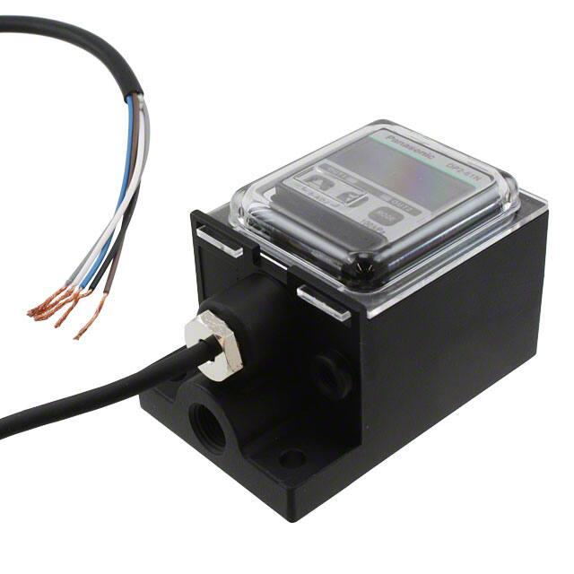
Standard type / DP2-2�
Flat type / DP2-4�
DP
2-20
–101
.3k
Pa
OU
T1
MO
0-A
DJ
Peak hold / bottom hold display
The peak value or the bottom value of
the varying pressure can be displayed.
This function is convenient for finding the
pressure variation range or for determining a reference for pressure settings.
MO
DE
Direct piping
Mounting on a
panel
Direct mounting on a wall
Light weight type / DP2-80
IP67 type / DP2-6�
The DP2 series covers worldwide usage with the Asian type,
the North American type and the
European type. Each type provides
the customary pressure unit,
suitable transistor output, and
pressure port.
Total weight
70 g approx.
Analog bar display
Pressure changes can also be displayed in an analog fashion using LED
bars. Hence, sudden pressure changes
can be recognized at a glance.
LED bars indicate the pressure level in steps
of 10 % F.S., regardless of the pressure unit.
(
(
Analog bar display
DE
OU
T2
MO
The sensor can
be mounted on
the suction head
of a chip mounter.
DE
Water and
dust proof
Pressure unit
The international system
of unit (SI)
European type
Digital display
Asian
type
North
American
European
Pressure port
kgf/cm2 (Positive
pressure type)
NPN and
Rc (PT) 1/8 or M5
mmHg (Vacuum analog voltage female thread
pressure type)
Asian
North
American
type
Output
Pa
psi (Positive
NPT 1/8 or
pressure type) NPN and
1
inHg (Vacuum analog voltage NPTF /8
female thread
pressure type)
bar
G (PF) 1/8
PNP and
analog voltage female thread
793
LED Bar Display
PE
Air
�ORDER GUIDE
0 to �101.3 kPa
DP2-21
0 to 100.0 kPa
DP2-21F
DP2-21F-P
Asian
North
American
DP2-20F
DP2-20F-P
DP2-22
0 to 1.000 MPa
DP2-22F
DP2-22F-P
Asian
North
American
Model No.
DP2-20
Asian
North
American
Asian
Rated pressure range
DP2-80
Pressure port
Rc (PT) 1/8
female thread
NPTF 1/8
female thread
Rc (PT) 1/8
female thread
NPTF 1/8
female thread
Rc (PT) 1/8
female thread
NPTF 1/8
female thread
M5 female thread
0 to �101.3 kPa
North
North
North
North
North
North
Asian European
Asian European
Asian European
Asian European
Asian European
American
American
American
American
American
American
100 kPa type
1 MPa type
�101 kPa type
100 kPa type
1 MPa type
Appearance
European
100 kPa type
1 MPa type
�101 kPa type
Positive pressure
Vacuum pressure
794
Positive pressure
IP67
Vacuum pressure
Positive pressure
PE
LED Bar Display
Flat
Vacuum pressure
Standard
Light weight
DP4
DP2
DP3
Digital Display
DP-M
�101 kPa type
Type
DP5/DPH
Head-separated
PRESSURE SENSORS
DP2
0 to 100.0 kPa
0 to 1.000 MPa
0 to �101.3 kPa
0 to 100.0 kPa
0 to 1.000 MPa
DP2-40N
NPT 1/8
female thread
DP2-40E
G (PF ) 1/8
female thread
DP2-41
Rc (PT) 1/8
female thread
DP2-41N
NPT 1/8
female thread
DP2-41E
G (PF) 1/8
female thread
DP2-42
Rc (PT) 1/8
female thread
DP2-42N
NPT 1/8
female thread
DP2-42E
G (PF) 1/8
female thread
DP2-60
Rc (PT) 1/8
female thread
DP2-60N
NPT 1/8
female thread
DP2-60E
G (PF) 1/8
female thread
DP2-61
Rc (PT) 1/8
female thread
DP2-61N
NPT 1/8
female thread
DP2-61E
G (PF) 1/8
female thread
DP2-62
Rc (PT) 1/8
female thread
DP2-62N
NPT 1/8
female thread
DP2-62E
G (PF) 1/8
female thread
Comparative output
NPN open-collector
transistor
PNP open-collector
transistor
NPN open-collector
transistor
PNP open-collector
transistor
NPN open-collector
transistor
PNP open-collector
transistor
NPN open-collector
transistor
PNP open-collector
transistor
NPN open-collector
transistor
PNP open-collector
transistor
NPN open-collector
transistor
PNP open-collector
transistor
NPN open-collector
transistor
PNP open-collector
transistor
NPN open-collector
transistor
PNP open-collector
transistor
NPN open-collector
transistor
PNP open-collector
transistor
�ORDER GUIDE
5 m 16.404 ft cable length type
Type
Standard
DP2-20
Vacuum pressure
�101 kPa type
Head-separated
DP5/DPH
5 m 16.404 ft cable length type is also available. (Standard: 2 m 6.562 ft)
PRESSURE SENSORS
DP2
5 m 16.404 ft cable length type
DP2-20-C5
DP2-20F
DP2-20F-P
DP2-21-C5
DP4
Standard
DP2-21
100 kPa type
DP2-21F
DP2-21F-P
Positive pressure
DP2-22
1 MPa type
DP2-22-C5
DP2-22F
DP2-80
Vacuum pressure
�101 kPa type
Digital Display
DP3
DP2
Light weight
DP2-22F-P
DP2-80-C5
DP2-40N
DP2-40E
Flat
DP2-41
100 kPa type
DP2-41-C5
DP2-41N
DP2-41E
Positive pressure
DP2-42
1 MPa type
DP2-42-C5
DP2-42N
DP-M
DP2-42E
DP2-60
Vacuum pressure
�101 kPa type
DP2-60N
LED Bar Display
PE
DP2-60E
IP67
DP2-61
100 kPa type
DP2-61N
The IP67 type is the standard
type with a 5 m 16.404 ft cable.
DP2-61E
Positive pressure
DP2-62
1 MPa type
DP2-62N
DP2-62E
Accessories
• DPX-01 [Pressure port attachment (Standard type only)]
• DPX-02 [Hexagon-socket-head plug for pressure port (Standard type only)]
Pressurer port attachment DPX-01
Hexagon-socket-head plug
for pressure port DPX-02
795
�PRESSURE SENSORS
DP5/DPH
Head-separated
DP4
DP2
DP3
Digital Display
OPTIONS
Sensor mounting bracket
Designation
Sensor
mounting
bracket
(For standard type)
Model No.
MS-DPX
Mounting bracket for standard type
Two M4 (length 6 mm 0.236 in) pan head screws and two spring
washers are attached.
[
]
DP
2-20
.3k
Pa
Straight bush
DPX-03
Changes the pressure port from female thread [Rc (PT) 1/8] to
male thread [R (PT) 1/8]
Panel mounting
bracket
(For standard type)
MS-DPX-2
It can be used for mounting on a panel
(1 to 3.2 mm 0.039 to 0.126 in thick).
DPX-04
It protects the sensor’s adjustment panel.
(It can be fitted when the panel mounting bracket is used.)
[
OU
T1
]
0-A
DJ
OU
T2
MO
Two M4 (length 6 mm 0.236 in)
pan head screws and two
spring washers are attached.
DE
Two M4 (length 6 mm 0.236 in)
pan head screws and two
spring washers are attached.
Straight bush
CA2-T2
Digital panel
controller
(Note)
NPN open-collector
transistor
This is a very small controller which allows two
independent threshold level settings.
• Supply voltage: 24 V DC�10 %
• No. of inputs: 1 No. (sensor input)
• Input range: 1 to 5 V DC
• Main functions:
Threshold level setting function, zero-adjust
function, scale setting function, hysteresis
setting function, start / hold function, autoreference function, power supply ON-delay
function, etc.
• DPX-03
Straight
bush
Panel mounting bracket,
Front protection cover
• MS-DPX-2
• DPX-04
Front protection
cover DPX-04
DP
2-2
0
–10
OU
1.3k
OU
T2
MO
CA-T2
CA-B2
This is a multi-functional controller having
mathematical functions, hold function, etc.
• Supply voltage: 100 to 240 V AC�10 %
• No. of inputs: 2 Nos. (sensor inputs)
• Input range: 1 to 5 V DC
NPN open-collector • Power supply for sensor: 12 V DC, 150 mA
• Main functions:
transistor
Mathematical functions, process number
selection function, hold function, scaling
NPN open-collector function, auto-reference function, power supply
transistor
ON-delay function, measurement start delay
With BCD output
function, hysteresis setting function, etc.
Pa
T1
0-A
DJ
CA-R2
DE
Relay contact
Panel mounting bracket
MS-DPX-2
Suitable for 1 to 3.2 mm
0.039 to 0.126 in thick panel
(
Digital panel controller
• CA2 series
Note: For further details, refer to p.864l for the ultra-compact digital panel controller CA2 series, and to
p.854l for the digital panel controller CA series.
• CA series
796
• MS-DPX-4
–101
MS-DPX-4
Front protection
cover
(For standard type)
• MS-DPX
Description
Back angled mounting bracket for standard type
Two M4 (length 6 mm 0.236 in) pan head screws and two spring
washers are attached.
PE
LED Bar Display
DP-M
DP2
)
�Type of pressure
Gauge pressure
0 to�101.3 kPa
Rated pressure range
5.1 to�101.3 kPa
0.052 to �1.033 kgf/cm2, 0.051 to �1.013 bar
0.74 to �14.70 psi, 38 to �760 mmHg
1.5 to �29.9 inHg
Set pressure range
Pressure withstandability
kPa, kgf/cm2, bar, psi, mmHg, inHg
kPa, kgf/cm2, bar, psi
MPa, kgf/cm2, bar, psi
10
12 to 24 V DC �
�15 % Ripple P-P 10 % or less
Supply voltage
NPN open-collector transistor
• Maximum sink current: 100 mA
• Applied voltage: 30 V DC or less (between comparative output and 0 V)
• Residual voltage: 1 V or less (at 100 mA sink current)
0.4 V or less (at 16 mA sink current)
PNP open-collector transistor
• Maximum source current: 100 mA
• Applied voltage: 30 V DC or less (between comparative output and �V)
• Residual voltage: 2 V or less (at 100 mA source current)
DC-12 or DC-13
Utilization category
Hysteresis
Equipped with 4 types of modes: hysteresis mode, window comparator mode, dual output mode, automatic sensitivity setting
mode (selectable by key operation)
1 digit (however, variable in hysteresis mode and 2 digits when using psi unit)
Within�0.2 % F.S.�1 digit
Repeatability
2.5 ms or less
Response time
Incorporated
Short-circuit protection
Analog voltage output
Output voltage: 1 to 5 V (over rated pressure range)
Zero-point: within 1 V�5 % F.S.
Span: within 4 V�5 % F.S.
Linearity: within�1 % F.S.
Output impedance: 1 kΩ approx.
DP-M
Output modes
5
1
Pressure
High pressure (Positive pressure type)
High vacuum (Vacuum pressure type)
31/2 digit red LED display (Sampling rate: 4 times/sec. approx.)
Display
Displayable pressure range
Analog bar display
Operation Comparative Output 1
indicators Comparative Output 2
Pollution degree
Protection
Ambient temperature
5.1 to�101.3 kPa
0.052 to �1.033 kgf/cm2, 0.051 to �1.013 bar
0.74 to �14.70 psi, 38 to �760 mmHg
1.5 to �29.9 inHg
�5.0 to 100.0 kPa
�0.051 to 1.020 kgf/cm2
�0.050 to 1.000 bar
�0.72 to 14.50 psi
LED bar display in steps of 10 % F.S. approx.
Orange LED (lights up when Comparative Output 1 is ON)
Green LED (lights up when Comparative Output 2 is ON)
3 (Industrial environment)
Standard, Flat and Light weight types: IP40 (IEC), IP67 type: IP67 (IEC)
�10 to�50 �C �14 to�122 �F (No dew condensation or icing allowed), Storage:�10 to �60 �C �14 to�140 �F
Ambient humidity
35 to 85 % RH, Storage: 35 to 85 % RH
EMC
EN 50081-2, EN 50082-2, EN 61000-6-2
Voltage withstandability
�0.050 to 1.000 MPa
�0.51 to 10.20 kgf/cm2
�0.50 to 10.00 bar
�7.2 to 145.0 psi
1,000 V AC for one min. between all supply terminals connected together and enclosure
Insulation resistance
50 MΩ, or more, with 500 V DC megger between all supply terminals connected together and enclosure
Vibration resistance
10 to 150 Hz frequency, 0.75 mm 0.030 in amplitude in X, Y and Z directions for two hours each
Shock resistance
Temperature characteristics
Asian
Pressure
port
North American
European
Material
Cable
Cable extension
Weight
Accessories
100 m/s2 acceleration (10 G approx.) in X, Y and Z directions for three times each
Over ambient temperature range �10 to�50 �C �14 to�122 �F : within�1 % F.S. of detected pressure at �20 �C�68 �F
Standard, Flat and IP67 types: Rc (PT) 1/8 female thread, Light weight type: M5 female thread
Standard type: NPTF 1/8 female thread, Flat and IP67 types: NPT 1/8 female thread
Flat and IP67 types: G (PF) 1/8 female thread
Front case: ABS, Rear case: PPS (glass fiber reinforced), Display surface: Acrylic
Pressure port attachment: Die-cast zinc alloy [Light weight type: POM (glass fiber reinforced), pressure port is brass (nickel plated)]
Front cover (IP67 type only): Polycarbonate
0.15 mm2 5-core oil resistant cabtyre cable, 2 m 6.562 ft long (IP67 type: 5 m 16.404 ft long)
Extension up to total 100 m 328.084 ft (less than 10 m 32.808 ft when conforming to CE marking) is possible with 0.3 mm2, or more, cable.
Standard type: 95 g approx., Flat type: 120 g approx., IP67 type: 370 g approx., Light weight type: 70 g approx.
Hexagon-socket-head plug for pressure port: 1 pc. (Standard type only), Pressure unit label: 1 pc.
Note: Model Nos. of North American standard type having the suffix ‘-P’ are PNP output type.
797
LED Bar Display
PE
)
Digital Display
DP3
DP2
50 mA or less
Current consumption
Environmental resistance
1.47 MPa
Non-corrosive gas
Selectable units
(
0 to 1.000 MPa
�0.050 to 1.000 MPa
�0.51 to 10.20 kgf/cm2
�0.50 to 10.00 bar
�7.2 to 145.0 psi
490 kPa
Applicable fluid
Comparative outputs
Comparative Output 1
Comparative Output 2
0 to 100.0 kPa
�5.0 to 100.0 kPa
�0.051 to 1.020 kgf/cm2
�0.050 to 1.000 bar
�0.72 to 14.50 psi
Output
voltage (V)
Model No.
Item
1MPa type
Flat
IP67
DP2-42
DP2-62
DP2-42N DP2-62N
DP2-42E DP2-62E
PRESSURE SENSORS
Vacuum pressure
Positive pressure
�101kPa type
100kPa type
Standard Light weight
Flat
IP67
Standard
Flat
IP67
Standard
DP2-20
DP2-80
DP2-60
DP2-21
DP2-41
DP2-61
DP2-22
Asian
North American (Note) DP2-20F(-P)
DP2-40N DP2-60N DP2-21F(-P) DP2-41N DP2-61N DP2-22F(-P)
DP2-40E DP2-60E
DP2-41E DP2-61E
European
Type
DP4
SPECIFICATIONS
Head-separated
DP5/DPH
DP2
�NPN output type
I/O circuit diagram
DP2
DP3
Digital Display
Wiring diagram
Color code
1 kΩ
ZD1
Tr1
(Gray) Analog voltage
output (Note1, 2)
(Black) Comparative Output 1
ZD3
(Blue) 0 V
Internal circuit
10 0kPa
Load
Load
100 mA max.
(White) Comparative Output 2
ZD2
Tr2
DP2-41
(Brown) �V
D
Sensor circuit
PRESSURE SENSORS
I/O CIRCUIT AND WIRING DIAGRAMS
DP4
DP5/DPH
Head-separated
DP2
�
�
12 to 24 V DC
�10 %
�15
100 mA max.
OUT1
OUT2
MODE
0-ADJ
Users’ circuit
Notes:1) When using the analog voltage output, take care to
connect external device of proper input impedance. Also,
when a cable extension is used, voltage drop due to
cable resistance should be taken into account.
Notes:2) The analog voltage output does not incorporate a shortcircuit protection circuit.
Notes:
Do not connect it directly to a power supply or a
capacitive load.
Brown
Gray To analog
input
Load
circuit
Load
Black
Symbols ... D: Reverse supply polarity protection diode
ZD1, ZD2, ZD3: Surge absorption zener diode
Tr1, Tr2: NPN output transistor
�
�
�10 %
�15
�
�
�10 %
�15
12 to 24 V DC
White
Blue
PNP output type
I/O circuit diagram
Wiring diagram
D
Tr1
Sensor circuit
PE
LED Bar Display
DP-M
Color code
ZD1
Tr2
DP2-41E
(Brown) �V
100 mA max.
ZD2
1 kΩ
ZD3
Internal circuit
(Black) Comparative Output 1
100 mA max.
(White) Comparative Output 2
(Gray) Analog voltage
output (Note1, 2)
(Blue) 0 V
Load
�
�
12 to 24 V DC
�10 %
�15
Load
OUT1
OUT2
MODE
0-ADJ
Users’ circuit
Notes:1) When using the analog voltage output, take care to
connect external device of proper input impedance. Also,
when a cable extension is used, voltage drop due to
cable resistance should be taken into account.
Notes:2) The analog voltage output does not incorporate a shortcircuit protection circuit.
Notes:2) Do not connect it directly to a power supply or a
capacitive load.
Symbols ... D: Reverse supply polarity protection diode
ZD1, ZD2, ZD3: Surge absorption zener diode
Tr1, Tr2: PNP output transistor
798
10 0kPa
Brown
Black
White
Gray To analog
Load
input
circuit
Blue
Load
12 to 24 V DC
�Error messages
• When an error occurs, take the following corrective action.
Error message
3
OUT1
OUT2
Positive
pressure
type
–101.3kPa
Vacuum
pressure
type
DP2-20
Applied pressure
exceeds the upper
limit of displayable
pressure range.
Positive
pressure
type
Applied pressure at the
Pressure is being applied pressure port should be
during zero-point adjust- brought to atmospheric presment.
sure and zero-point adjustment should be done again.
Functional description
2
Corrective action
Overcurrent due to short- Switch off the power supply
circuit.
and check the load.
Operation
• If setting is impossible even with pressing the MODE key,
verify whether the key-protect function is enabled. Please
note that pressing down on the MODE key for an
extended moment will enable the key-protect function as
soon as the key is released.
• If using the window comparator mode, set the pressure
value so that there is a difference of 3 digits, or more,
between Set Value 1 (P-1) and Set Value 2 (P-2). No
output will be possible with a 0 to 2 digit difference.
1
Cause
Applied pressure
exceeds the lower
limit of displayable
Applied pressure should be
pressure range.
brought within the rated
Applied pressure pressure range.
exceeds the lower
limit of displayable
pressure range.
Vacuum
pressure
type
• This product is not a safety sensor. Its use is not
intended or designed to protect life and prevent
body injury or property damage from dangerous
parts of machinery. It is a normal pressure
detection sensor.
• The DP2 series is designed for use with noncorrosive gas. It cannot be used with liquid or corrosive gas.
Applied pressure
exceeds the upper
limit of displayable
pressure range.
PRESSURE SENSORS
DP4
All models
Head-separated
DP5/DPH
PRECAUTIONS FOR PROPER USE
Digital Display
DP3
DP2
DP2
The analog voltage output does not incorporate a shortcircuit protection circuit. Do not directly connect a power
supply or a capacitive load.
5
Description
Function
31/2 digit LED
1 display (Red)
Displays measured pressure, settings, error
messages and key-protect status.
Comparative Output 1
2 operation indicator
Lights up when Comparative Output 1 is ON.
(Orange)
Comparative Output 2
3 operation indicator
Lights up when Comparative Output 2 is ON.
4 Increment key (
5 Decrement key (
6
Mode selection key
( MODE )
• In the initial setting mode, pressing the
key changes the settable digit.
• In the Set Value 1, 2 modes, pressing
the key changes the set value to the
high pressure side in case of positive
pressure type sensor and to the high
)
vacuum side in case of vacuum pressure type sensor.
• In the sensing mode, if the key is
pressed continuously for 4 sec. or more,
the display shows peak hold value.
• In the initial setting mode, pressing the
key changes the set conditions.
• In the Set Value 1, 2 modes, pressing
the key changes the set value to the
low pressure side in case of positive
) pressure type sensor and to the low
vacuum side in case of vacuum pressure type sensor.
• In the sensing mode, if the key is
pressed continuously for 4 sec. or more,
the display shows bottom hold value.
In the sensing mode, if both the keys are pressed
simultaneously, zero-point adjustment is done.
(Green)
• Each press of the key changes the selected
mode to sensing mode, Set Value 1 (P-1) set
mode and Set Value 2 (P-2) set mode.
• In the sensing mode, if the key is pressed
continuously for about 3 sec., key-protect can
be set / released.
• In the sensing mode, if the mode selection
key is pressed while pressing the increment
key (
), the initial setting mode is obtained.
• Make sure that the power supply is off while wiring.
• Verify that the supply voltage variation is within the rating.
• If power is supplied from a commercial switching regulator,
ensure that the frame ground (F.G.) terminal of the power
supply is connected to an actual ground.
• In case noise generating equipment (switching regulator,
inverter motor, etc.) is used in the vicinity of this sensor,
connect the frame ground (F.G.) terminal of the equipment
to an actual ground.
• Do not run the wires together with high-voltage lines or
power lines or put them in the same raceway. This can
cause malfunction due to induction.
Conditions in use for CE conformity
• The DP2 series is a CE conformity product complying with
EMC Directive. The harmonized standard with regard to
immunity that applies to this product is EN 61000-6-2
(Note) and the following condition must be met to conform
to that standard.
Condition
• The sensor should be connected less than 10 m 32.808 ft
from the power supply.
Note: The EN 50082-2 that previously applied to the products for conforming to
EMC Directive was replaced by EN 61000-6-2 starting April 1st, 2002.
799
LED Bar Display
PE
Wiring
6
4
DP-M
MODE
0-ADJ
�PRESSURE SENSORS
DP5/DPH
Head-separated
DP4
DP2
PRECAUTIONS FOR PROPER USE
All models
Setting
• If key-protect has been set, make sure to release key-protect before operating the keys.
(Please refer to ‘Key-protect function’ on p.801 for the procedure.)
• Set Value 1 (P-1) and Set Value 2 (P-2) can be made common for all the output modes.
• The setting of Set Value 2 (P-2) with respect to Set Value 1 (P-1) can only be towards the high pressure side in case of
the positive pressure type sensor and only towards the high vacuum side in case of the vacuum pressure type sensor.
• Set Value 3 (P-3) is automatically set to the mid-value of Set Value 1 (P-1) and Set Value 2 (P-2).
(When setting the pressure value for the automatic sensitivity mode)
• The conditions which are set are stored in an EEPROM. Kindly note that the EEPROM has a life span and its guaranteed
life is 100,000 write operation cycles.
DP2
DP3
Digital Display
Setting procedure
1 Zero-point adjustment
2 Initial setting
3 Pressure value setting
Measurement
Adjust zero-point
Set ‘Display’, ‘Output mode’,
and ‘Unit’
Enter Set Value 1 (P-1), Set Value 2
(P-2), Set Value 3 (P-3)
Commence measurement
on completion of setting
1 Zero-point adjustment
3 Pressure value setting
• The displayed pressure when the pressure port is left
open is adjusted to zero.
For the case when output mode is set to either hysteresis
mode ( ), window comparator mode ( ) or dual output
mode ( ).
DP2-20
–101.3kPa
OUT1
OUT2
• The sensor will automatically enter the sensing
mode when power is supplied.
• Let the pressure port be at atmospheric pressure
(i.e., no applied pressure condition), and press,
simultaneously, the increment and decrement
keys continuously.
•
is displayed and, when the fingers are
released, zero-point adjustment is completed and
the sensor returns to the sensing mode.
MODE
DP-M
0-ADJ
• ‘Set Value 1 (P-1)’ and Set Value 2 (P-2)’ of the comparative outputs are set.
DP2-20
OUT1
–101.3kPa
OUT2
MODE
0-ADJ
• Pressure ‘Unit’, ‘Display’ and ‘Output mode’ of the
comparative outputs are set.
DP2-20
–101.3kPa
OUT1
OUT2
• In the sensing mode, press
ing
key.
MODE
key while press-
• Initial setting is displayed.
• If sensor is being used for the first time,
displayed.
MODE
0-ADJ
is
• The settable digit blinks.
• The settable digit changes when
key is
pressed and the setting is changed when
key
is pressed.
Change with
key
3rd digit
2nd digit
1st digit
Unit
Output mode
Display
Vacuum
Positive
pressure type pressure type
PE
LED Bar Display
2 Initial setting
: kPa or
MPa
: Hysteresis
mode
: Digital
display
: kgf/cm2
: Window
comparator
mode
: Dual output
mode
: Analog
bar
display
: bar
: psi
: mmHg
: Automatic
sensitivity
setting mode
• Press MODE key in the sensing mode to set to Set
Value 1 (P-1) set mode.
• Enter Set Value 1 (P-1) using
key and
key.
• Then, press MODE key to set to Set Value 2 (P-2)
set mode.
• Enter Set Value 2 (P-2) using
key and
key.
• Then, press MODE key to set to sensing mode.
For the case when output mode is set to automatic sensitivity
setting mode ( ).
• ‘Set Value 1 (P-1)’, ‘Set Value 2 (P-2)’ and ‘Set Value 3
(P-3)’ of the comparative outputs are set.
DP2-20
OUT1
–101.3kPa
OUT2
MODE
0-ADJ
• Press MODE key in the sensing mode to set to Set
Value 1 (P-1) set mode.
• Within the required permissible pressure range,
having created a pressure state which is nearest
to the atmospheric pressure, press
key to
enter Set Value 1 (P-1).
• Then, press MODE key to set to Set Value 2 (P-2)
set mode.
• Within the required permissible pressure range,
having created a pressure state which is nearest
to the high pressure end (for a positive pressure
type sensor) or the high vacuum end (for a
vacuum pressure type sensor), press
key to
enter Set Value 2 (P-2).
• Then, press MODE key to set to Set Value 3 (P-3)
set mode.
• Check Set Value 3 (P-3) which has been set
automatically. When Set Value 3 (P-3) is to be
changed, enter Set Value 3 (P-3) using
key
and
key.
• After checking and setting, press
sensing mode.
MODE
key to set to
: inHg
• The automatically set Set Value 3 (P-3) can be manually changed
to a value between Set Value 1 (P-1) and Set Value 2 (P-2).
• If using the window comparator mode, set the pressure value
so that there is a difference of 3 digits, or more, between Set
Value 1 (P-1) and Set Value 2 (P-2). No output will be possible
with a 0 to 2 digit difference.
800
�All models
1
1 MPa
1�103
1�
1�102
OUT1
OUT2
MODE
0-ADJ
1 psi
6.89473
–101.3kPa
OUT1
OUT2
MODE
0-ADJ
1.01972�10
1
1.01972
1�
10�2
1�10
psi
1.45038�
10�1
1 inHg
1 atm
3.3864
1
3.3864�10�3 3.4531�10�2 3.3864�10�2
1.01325�102 1.01325�10�1
• In the sensing mode, press MODE key continuously
for about 3 sec. and release it immediately when
is displayed.
• Key-protect is set and the sensor returns to the
sensing mode.
• In the sensing mode, press MODE key continuously
for about 3 sec. and release it immediately when
is displayed.
1.03323
mmHg
(Torr)
inHg
atm
7.50062
0.2953
9.86923�10�3
1.45038�102 7.50062�103 0.2953�103
9.86923
9.80665�10�1 1.42234�10 7.35559�102 2.8959�10 9.67841�10�1
6.89473�10�3 7.03065�10�2 6.89473�10�2
Release of key-protect
DP2-20
1
10�2
bar
1.45038�10 7.50062�102
1
1 mmHg
1.33322�10�1 1.33322�10�4 1.35951�10�3 1.33322�10�3 1.93368�10�2
(1 Torr)
Setting of key-protect
–101.3kPa
1.01972�
1�10�1
Key-protect function
• Key-protect is a function which prevents any unintentional
change in the conditions which have been entered in each
setting mode by making the sensor not to respond to the
key operations.
DP2-20
10�3
1 kgf/cm2 9.80665�10 9.80665�10�2
1 bar
kgf/cm2
1.01325
0.4912
5.17147�10
1
2.5400�10
2.953�10
9.86923�10�1
2.036
6.80457�10�2
DP4
1 kPa
MPa
3.9370�10�2 1.31579�10�3
1
1.46960�10 7.60000�102 2.9921�10
3.342�10�2
1
Others
• Use within the rated pressure range.
• Do not apply pressure exceeding the pressure withstandability value. The diaphragm will get damaged and
correct operation shall not be maintained.
• Do not use during the initial transient time (0.5 sec.) after
the power supply is switched on.
• Avoid use of standard type, flat type and light weight type
of sensors in places where steam and dust is excessive.
• Take care that the sensor does not come in direct contact
with water, oil, grease, or organic solvents, such as,
thinner, etc.
• Do not insert wires, etc., into the pressure port. The
diaphragm will get damaged and correct operation shall
not be maintained.
• Do not operate the keys with pointed or sharp objects.
• Key-protect is released and the sensor returns to the
sensing mode.
801
DP-M
• For example, if 2 kPa is to be expressed
in kgf/cm2,
since 1 kPa�1.01972�10�2 kgf/cm2,
2 kPa becomes
2�1.01972�10�2 c 0.020 kgf/cm2.
kPa
Digital Display
DP3
DP2
Conversion procedure
Conversion table for pressure units
LED Bar Display
PE
Conversion of pressure units
• In the DP2 series, the conversion
to different units is automatically
done on changing the setting of
the pressure unit. However, this
conversion can also be obtained
by multiplying the values by the
coefficients given in the table on
the right.
PRESSURE SENSORS
PRECAUTIONS FOR PROPER USE
Head-separated
DP5/DPH
DP2
�PRESSURE SENSORS
DP5/DPH
Head-separated
DP2
PRECAUTIONS FOR PROPER USE
Standard type
Setting of pressure lead direction
• The pressure lead direction can be changed by
dismantling the pressure port attachment and changing
the mounting direction. The tightening torque of the
hexagon-socket-head bolt (length: 9 mm 0.354 in or less)
should be 0.29 N m or less.
DP4
Note: Make sure to close any unused pressure port with the hexagonsocket-head plug supplied as accessory.
Main body
DP2
DP3
Digital Display
(Accessory for MS-DPX)
Spring washer
Sensor mounting bracket
MS-DPX (optional)
Pressure
ports
Hexagon-socket-head plug
Piping
• When connecting a hexagon-socket-head plug or coupling
to the pressure port, hold the hexagonal part of the
pressure port with a 12 mm 0.472 in spanner and make
sure that the tightening torque is 9.8 N m or less. Also, in
order to prevent any leakage, wind a sealing tape on the
coupling when connecting.
However, sealing tape is not required for North American
type (DP2-�F�) using NPTF 1/8 coupling. (Sealing tape is
required if NPT 1/8 coupling is used.)
PE
LED Bar Display
DP-M
M4 (length 6 mm 0.236 in)
pan head screw
(Accessory for MS-DPX)
Hexagon-socket-head bolts
Pressure port
attachment
Mounting
• When mounting the sensor with the sensor mounting
bracket, etc., the tightening torque should be 1.2 N m or
less.
12 mm 0.472 in spanner
Flat type
Light weight type
Setting of pressure lead direction
• The pressure lead direction can be changed by
dismantling the pressure port attachment and changing
the mounting direction. The tightening torque of the
hexagon-socket-head bolt (length: 9 mm 0.354 in or less)
should be 0.29 N m or less.
Piping
• When connecting a coupling to the pressure port, hold the
pressure port attachment with a 16 mm 0.630 in (light
weight type: 10 mm 0.394 in) spanner and make sure that
the tightening torque is 9.8 N m or less (light weight type:
1.47 N m or less). Also, in order to prevent any leakage,
wind a sealing tape on the coupling when connecting.
Pressure port attachment
Hexagon-socket-head bolts
Main body
2-"4.3 mm "0.169 in
mounting holes
Pressure port
802
16 mm 0.63 in
(light weight type: 10 mm 0.394 in)
spanner
�IP67 type
DP4
Hook
Digital Display
DP3
DP2
Guide holes
DP-M
Piping for atmospheric pressure inlet port
• If there is a possibility of water
Safe place, where
entering into the sensor
there is no exposure to water
enclosure through the atmoAtmospheric
spheric pressure inlet port,
pressure inlet port
connect a tube to the atmoM5 coupling
spheric pressure inlet port
through a M5 coupling and
extend the other end of the
Tube
tube to a safe place. In this
case, ensure that this end of
Pressure measurement
inlet port
the tube does not get clogged.
Fitting of front cover
• Insert the bosses on the front cover into the guide holes at
the bottom of the pressure port attachment, and push in
the direction of the arrow to fit the hook.
When removing the front cover, release the hook first.
LED Bar Display
PE
Piping for pressure measurement inlet port
• When connecting a coupling to the pressure measurement
inlet port, hold the pressure port attachment with a
spanner and make sure that the tightening torque is
9.8 N m or less. Also, in order to prevent any leakage,
wind a sealing tape on the coupling when connecting.
PRESSURE SENSORS
PRECAUTIONS FOR PROPER USE
Head-separated
DP5/DPH
DP2
803
�DIMENSIONS (Unit: mm in)
DP2-20� DP2-21�
DP2-22�
DP5/DPH
Head-separated
PRESSURE SENSORS
DP2
(2.1)
(0.083)
Standard type
31.6
1.244
30
1.181
(25.8)
(1.016)
DP4
2-M3 hexagon-socket-head bolts
20
0.787
5
0.197
(11)
(0.433) 30 31.6
1.181 1.244
(18.9)
(0.744) (10.9)
(0.429)
Pressure port
Rc (PT) 1/8
female thread (Note)
Comparative Output 2
operation indicator (Green)
Mode selection key
Decrement key
(9)
(0.354)
(18)
(0.709)
Comparative Output 1
operation indicator (Orange)
8
0.315
13
0.512
14
0.551
"3.7 "0.146 cable, 2 m 6.562 ft long
12
0.472
Note: NPTF 1/8 female thread for North American type.
DP2-80
Light weight type
DP-M
(2.1)
(0.083)
30
1.181
(25.8)
(1.016)
31/2 digit
LED display (Red)
33.5
1.319
23.5
0.925
(11)
(0.433)
30
1.181
41
1.614 (23.7)
(0.933) (15.7)
(0.618) (10.8)
(0.425)
MODE
Comparative Output 2
operation indicator (Green)
6.2 0.244
Mode selection key
2-"8 "0.315, 4.4 0.173 deep
2-"4.3 "0.169 mounting holes
Comparative Output 1
operation indicator (Orange)
(9)
(0.354)
(18)
(0.709)
20
0.787
Decrement key
Increment key
10
0.394
18
0.709
Pressure port
M5 female thread, 4 0.157 deep
5
0.197
"3.7 "0.146 cable, 2 m 6.562 ft long
DP2-40� DP2-41�
Flat type
DP2-42�
(2.1)
(0.083)
30
1.181
(25.8)
(1.016)
31/2 digit
LED display (Red)
35
1.378
23.5
0.925
(11)
(0.433) 30
1.181
44.7
1.760 (27.9)
(1.098) (19.9) (15)
(0.783) (0.591)
MODE
Comparative Output 2
operation indicator (Green)
5.7 0.224
2-"8 "0.315, 4.4 0.173 deep
2-"4.3 "0.169 mounting holes
Mode selection key
(9)
(0.354)
(18)
(0.709)
20
0.787
Comparative Output 1
operation indicator (Orange)
Decrement key
Increment key
Pressure port
Rc (PT) 1/8
female thread (Note)
8.2
0.323
16
0.630
19.5
0.768
"3.7 "0.146 cable, 2 m 6.562 ft long
Note: NPT 1/8 female thread for North American type, and G (PF) 1/8 female thread for European type.
804
2-M4
20
0.787
MODE
Increment key
DP2
DP3
Digital Display
38.5
1.516
23.5
0.925
31/2 digit
LED display (Red)
(6)(0.236)
PE
LED Bar Display
The CAD data in the dimensions can be downloaded from the SUNX website: http://www.sunx.co.jp/
�DIMENSIONS (Unit: mm in)
The CAD data in the dimensions can be downloaded from the SUNX website: http://www.sunx.co.jp/
2.5
0.098
(10.1)
(0.398)
46
1.811
(25.8)
(1.016)
Head-separated
DP5/DPH
DP2-60� DP2-61�
IP67 type
DP2-62�
31/2 digit
LED display (Red)
(11)
(0.433)
Comparative Output 2
operation indicator (Green)
MODE
DP4
69.5
2.736
(45.1)
(1.776) (37.1)
(1.461) (32.2)
(1.268)
PRESSURE SENSORS
DP2
Mode selection key
Comparative Output 1
operation indicator (Orange)
Decrement key
6 0.236
"3.7 "0.146 cable,
5 m 16.404 ft long
(9)
(0.354)
(18)
(0.709)
34
1.339
Digital Display
DP3
DP2
2-"4.5 "0.177
mounting holes
Increment key
26
1.024
17
0.669
Atmospheric pressure inlet port
M5 female thread, 4 0.157 deep
43
1.693
DP-M
22
0.866
8.5
0.335
Pressure measurement inlet port
Rc (PT) 1/8 female thread (Note)
MS-DPX
40
1.575
25
0.984
Sensor mounting bracket for standard type (Optional)
Assembly dimensions
5.8
0.228
25
0.984
2-"4.2 "0.165
mounting holes
11
0.433
31.5
1.240
20
0.787
12.5
0.492
LED Bar Display
PE
Note: NPT 1/8 for North American type, and G (PF) 1/8 for European type.
2-"4.2 "0.165 mounting holes
11
0.433
20
0.787
48.5
39.5 1.909
28.5 1.555
1.122
2-"4.2 "0.165
mounting holes
30
1.181
31.6
1.244
3.6
0.142
20
0.787
38.5
1.516
8
0.315
45.8
1.803
MODE
45.5
1.791
20
0.787
40
1.575
5.8
0.228
30
1.181
14.2
0.559
30
1.181
24
0.945
t 1.6
0.063
Material: Cold rolled carbon steel (SPCC)
(Uni-chrome plated)
Two M4 (length 6 mm 0.236 in) pan head screws
and two spring washers are attached.
805
�PRESSURE SENSORS
DP5/DPH
Head-separated
DP2
DIMENSIONS (Unit: mm in)
MS-DPX-4
The CAD data in the dimensions can be downloaded from the SUNX website: http://www.sunx.co.jp/
Back angled mounting bracket for standard type (Optional)
Assembly dimensions
30
1.181
20
0.787
12.5
0.492
3-"4.2 "0.165
mounting
holes
11.4
0.449
31.6
1.244
20
0.787
DP4
50
1.969
28.2
1.110
14.5
0.571
1.6
0.063
MODE
24.5
0.965
11.5
0.453
"4.5 "0.177
mounting hole
DP2
DP3
Digital Display
41.5
1.634
28.5
1.122
50.3
1.980
34.5
1.358
18.7
0.736
6 0.236
4.5
0.177
5.5
0.217
20
0.787
"4.5 "0.177
mounting hole
24
0.945
30
1.181
Mounting oblong hole
Material: Cold rolled carbon steel (SPCC)
(Uni-chrome plated)
Two M4 (length 6 mm 0.236 in) pan head screws
and two spring washers are attached.
MS-DPX-2
DPX-04
20
0.787
Mounting oblong hole
Panel mounting bracket, front protection cover for standard type (Optional)
Assembly dimensions
DP-M
Panel cut-out dimensions
56
2.205
42.7
1.681
PE
LED Bar Display
36 �00.5
1.417�00.02
9.7
0.382
40
1.575
30
1.181
40
30
1.575 1.181
43.7
1.720
34
1.339
4.5
0.177
3 0.118
80
3.150
36 �00.5
1.417�00.02
42.7
1.681
MODE
portion shows the front protection cover.
Material: Polycarbonate (Front protection cover)
Nylon 6, Stainless steel (SUS304)(Panel mounting bracket)
806
Note: The panel thickness should be 1 to 3.2 mm 0.039 to 0126 in.
�


 工商网监
湘ICP备2023018690号
工商网监
湘ICP备2023018690号
