747
FIBER
SENSORS
Compact Size Digital Pressure Sensor
DP4 SERIES
Related Information
■■General terms and conditions............ F-17
■■Glossary of terms........................ P.1373~
For Gas
■■Sensor selection guide.................. P.661~
■■General precautions...................... P.1405
LASER
SENSORS
PHOTOELECTRIC
SENSORS
Conforming to
EMC Directive
MICRO
PHOTOELECTRIC
SENSORS
Recognition
AREA
SENSORS
LIGHT
CURTAINS
PRESSURE /
FLOW
SENSORS
INDUCTIVE
PROXIMITY
SENSORS
* Passed the UL 991 Environment Test
PARTICULAR
USE SENSORS
* UL 61010C-1 compatible, Passed the UL 991
Environment Test based on SEMI S2-0200.
[Category applicable for semiconductor
manufacturing: TWW2, Process Equipment]
[Applicable standards: UL 61010C-1]
[Additional test / evaluation standards as per intended
use: UL 991, SEMI S2-0200]
SENSOR
OPTIONS
SIMPLE
WIRE-SAVING
UNITS
WIRE-SAVING
SYSTEMS
MEASUREMENT
SENSORS
panasonic-electric-works.net/sunx
Digital
STATIC CONTROL
DEVICES
ENDOSCOPE
LASER
MARKERS
PLC /
TERMINALS
HUMAN MACHINE
INTERFACES
ENERGY CONSUMPTION
VISUALIZATION
COMPONENTS
FA COMPONENTS
New shape makes it most suitable for panel mounting
Can be mounted on a DIN rail
Can be mounted closely
The sensor can be mounted even on a 35 mm 1.378 in
width DIN rail by using the optional DIN rail mounting
bracket (MS-DP-2). It can be mounted in a narrow space
inside of your device.
Even when you use more than
one sensor at the same time, you
can mount them close together in
one hole to save both space and
man-hours.
Mountable from four different directions
MACHINE VISION
SYSTEMS
UV CURING
SYSTEMS
Flow
DP4
40 mm
1.575 in
60 mm
2.362 in
MS-DP-2
Supplied with a simple-to-mount panel mounting bracket
Selection
Guide
Pressure/
Digital Display
Pressure/
Head-separated
Other Products
Automatic
sensitivity setting
A panel mounting bracket MS-DP-1 is enclosed to
enable simple mounting of the sensor onto the panel
surface, thus contributing to the total cost reduction.
Light-weight, compact design
A compact form specifically designed for mounting on
an equipment panel. It only uses half the space of our
conventional product and provides the light weight of just
30 g (cables excluded).
Panel mounting
bracket
MS-DP-1
Accessory
The bracket is suitable for a panel
with a thickness of 1 to 6 mm �
0.035 to 0.236 in.
*T
� he panel mounting bracket MS-DP-5 (optional) enabling the sensors
to be attached to each other laterally is available.
40 mm 1.575 in
20 mm 0.787 in
Incorporated with the memory bank function
You can store two patterns of set values. Hence, the
setup can be changed by a single touch.
�Compact Size Digital Pressure Sensor
DP4 SERIES
APPLICATIONS
748
FIBER
SENSORS
Checking IC absorption
Checking degree of vacuum for
vacuum molding
Checking reference pressure of device
LASER
SENSORS
PHOTOELECTRIC
SENSORS
MICRO
PHOTOELECTRIC
SENSORS
AREA
SENSORS
DP4-50
LIGHT
CURTAINS
DP4-50
DP4-52
PRESSURE /
FLOW
SENSORS
INDUCTIVE
PROXIMITY
SENSORS
PARTICULAR
USE
SENSORS
ORDER GUIDE
–101 kPa
type
±100 kPa
type
0 to 1.000 MPa
Compound
pressure
0 to –101.3 kPa
1 MPa type
Rated pressure
range (Note)
Vacuum
pressure
Appearance
Positive
pressure
Type
SENSOR
OPTIONS
• MS-DP-1 (Panel mounting bracket)
Pressure port
Output
DP4-50
NPN open-collector transistor
DP4-50P
PNP open-collector transistor
DP4-52
SIMPLE
WIRE-SAVING
UNITS
WIRE-SAVING
SYSTEMS
MEASUREMENT
SENSORS
STATIC
CONTROL
DEVICES
NPN open-collector transistor
ENDOSCOPE
DP4-52P
PNP open-collector transistor
LASER
MARKERS
DP4-57
NPN open-collector transistor
M5 female thread
–100.0 to 100.0 kPa
Note: The rated pressure range indicates the range for full product performance.
Accessory
Model No.
DP4-57P
PNP open-collector transistor
PLC /
TERMINALS
HUMAN
MACHINE
INTERFACES
ENERGY
CONSUMPTION
VISUALIZATION
COMPONENTS
FA
COMPONENTS
MACHINE
VISION
SYSTEMS
UV
CURING
SYSTEMS
Selection
Guide
Pressure/
Digital Display
Pressure/
Head-separated
Flow
Other
Products
DP4
�749
FIBER
SENSORS
Compact Size Digital Pressure Sensor
DP4 SERIES
OPTIONS
LASER
SENSORS
PHOTOELECTRIC
SENSORS
Designation
MICRO
PHOTOELECTRIC
SENSORS
Connector
AREA
SENSORS
Connector
attached cable
LIGHT
CURTAINS
PRESSURE /
FLOW
SENSORS
INDUCTIVE
PROXIMITY
SENSORS
PARTICULAR
USE
SENSORS
Model No.
Connector
Description
• CN-63
Connector pin
CN-63
Set of 10 housings and 30 connector pins
CN-63-C2
Length: 2 m 6.562 ft
CN-63-C5
Length: 5 m 16.404 ft
MS-DP-2
For installation to 35 mm 1.378 in width DIN rail
MS-DP-3
Vertical mounting bracket
MS-DP-4
Horizontal mounting bracket
MS-DP-5
Enables the sensors to be attached to each other laterally and
mounted on the panel.
WIRE-SAVING
SYSTEMS
3
DIN rail
mounting bracket
Sensor mounting
bracket
Horizontal
multiple panel
mounting bracket
2
• MS-DP-2
Sensor mounting bracket
• MS-DP-5
• MS-DP-3
Panel fixing screw
(Accessory)
ENDOSCOPE
LASER
MARKERS
PLC /
TERMINALS
HUMAN
MACHINE
INTERFACES
ENERGY
CONSUMPTION
VISUALIZATION
COMPONENTS
FA
COMPONENTS
MACHINE
VISION
SYSTEMS
UV
CURING
SYSTEMS
Selection
Guide
Pressure/
Digital Display
Pressure/
Head-separated
Flow
Other
Products
DP4
MS-DP-5
* �The above illustration shows two units connected in
sequence.
Housing
3
2
1
DIN rail mounting bracket
Horizontal multiple panel mounting bracket
MEASUREMENT
SENSORS
STATIC
CONTROL
DEVICES
• CN-63-C2
• CN-63-C5
1
0.2 mm2 3-core cabtyre cable with connector
Cable outer diameter: ø3.8 mm ø0.150 in
SENSOR
OPTIONS
SIMPLE
WIRE-SAVING
UNITS
Connector
attached cable
• MS-DP-4
Label
space
Designed with a 9 mm 0.354 in label
space to enable the labeling of the
sensors with a label printer (9 mm
0.354 in width) for sensor number and
application data.
�Compact Size Digital Pressure Sensor
DP4 SERIES
SPECIFICATIONS
Type
Item
Model No.
FIBER
SENSORS
Vacuum pressure
Positive pressure
Compound pressure
–101 kPa type
1 MPa type
±100 kPa type
NPN output
PNP output
NPN output
PNP output
NPN output
PNP output
DP4-50
DP4-50P
DP4-52
DP4-52P
DP4-57
DP4-57P
Type of pressure
Rated pressure range
Set pressure range
Pressure withstandability
Gauge pressure
0 to –101.3 kPa
0 to 1.000 MPa
–100.0 to 100.0 kPa
5.1 to –101.3 kPa
0.052 to –1.033 kgf/cm2, 0.051 to –1.013 bar
0.74 to –14.70 psi, 38 to –760 mmHg
1.5 to –29.9 inHg
–0.050 to 1.050 MPa
–0.51 to 10.71 kgf/cm2
–0.50 to 10.50 bar
–7.2 to 152.2 psi
–101.3 to 105.0 kPa
–1.033 to 1.071 kgf/cm2
–1.013 to 1.050 bar
–14.68 to 15.22 psi
490 kPa
1.470 MPa
490 kPa
Applicable fluid
Non-corrosive gas
Hysteresis
Repeatability
Within ±0.2 % F.S. ± 1 digit (within ±3 digits)
+10
NPN open-collector transistor
PNP open-collector transistor
• Maximum sink current: 100 mA
• Maximum source current: 100 mA
• Applied voltage: 30 V DC or less (between output and 0 V)
• Applied voltage: Same as supply voltage (between output and +V)
• Residual voltage: �1 V or less (at 100 mA sink current)
• Residual voltage: 2 V or less (at 100 mA source current)
0.4 V or less (at 16 mA sink current)
DC-12 or DC-13
Output operation
Display
Displayable pressure
range
Equipped with 4 types of modes: Hysteresis mode, window comparator mode, automatic sensitivity setting mode,
forced output mode (selectable by key operation)
2 ms, 16 ms, 128 ms, 512 ms or less (selectable by key operation)
3 1/2 digit LCD display (with red and green backlight)
(Sampling rate: 256 ms, 512 ms, 1,024 ms selectable by key operation)
5.1 to –101.3 kPa
0.052 to –1.033 kgf/cm2, 0.051 to –1.013 bar
0.74 to –14.70 psi, 38 to –760 mmHg
1.5 to –29.9 inHg
–0.050 to 1.050 MPa
–0.51 to 10.71 kgf/cm2
–0.50 to 10.50 bar
–7.2 to 152.2 psi
–101.3 to 105.0 kPa
–1.033 to 1.071 kgf/cm2
–1.013 to 1.050 bar
–14.68 to 15.22 psi
Operation display
LCD segment is red when the output is ON, and green when the output is OFF
Environmental resistance
Ambient temperature
Ambient humidity
EMC
Voltage withstandability
3 (Industrial environment)
0 to +50 °C +32 to +122 °F (No dew condensation), Storage: –10 to +60 °C +14 to +140 °F
Over ambient temperature range +10 to +40 °C +50 to +104 °F: within ±2 % F.S. of detected pressure at +25 °C +77 °F
Over ambient temperature range 0 to +50 °C +32 to +122 °F: within ±5 % F.S. of detected pressure at +25 °C +77 °F
Suitable cable
Weight
Accessories
LASER
MARKERS
HUMAN
MACHINE
INTERFACES
ENERGY
CONSUMPTION
VISUALIZATION
COMPONENTS
FA
COMPONENTS
MACHINE
VISION
SYSTEMS
UV
CURING
SYSTEMS
Pressure/
Head-separated
Temperature characteristics
Wire material
STATIC
CONTROL
DEVICES
1,000 V AC for one min. between all supply terminals connected together and enclosure
100 m/s2 acceleration (10 G approx.) in X, Y and Z directions for three times each
Cable length
MEASUREMENT
SENSORS
Pressure/
Digital Display
Shock resistance
Lead wire diameter
WIRE-SAVING
SYSTEMS
EN 61000-6-2, EN 61000-6-4
10 to 150 Hz frequency, 0.75 mm 0.030 in amplitude, in X, Y and Z directions for two hours each
Conductor cross-section area
SENSOR
OPTIONS
Selection
Guide
50 MΩ, or more, with 500 V DC megger between all supply terminals connected together and enclosure
Connecting method
INDUCTIVE
PROXIMITY
SENSORS
35 to 85 % RH, Storage: 35 to 85 % RH
Vibration resistance
Material
PRESSURE /
FLOW
SENSORS
IP40 (IEC)
Insulation resistance
Pressure port
LIGHT
CURTAINS
PLC /
TERMINALS
Incorporated
Bar display in steps of 14 % F.S. approx.
Protection
AREA
SENSORS
ENDOSCOPE
Analog bar display
Pollution degree
MICRO
PHOTOELECTRIC
SENSORS
NO / NC (selectable by key operation)
Short-circuit protection
Response time
PHOTOELECTRIC
SENSORS
SIMPLE
WIRE-SAVING
UNITS
40 mA or less
Utilization category
Output modes
Within ±0.2 % F.S. ± 2 digits
(within ±6 digits)
12 to 24 V DC –15 % Ripple P-P 10 % or less
Current consumption
LASER
SENSORS
PARTICULAR
USE
SENSORS
1 digit (however, variable in hysteresis mode)
Supply voltage
Output
750
M5 female thread
Front case: ABS, LCD display: PET, Rear case: PBT [M5 threaded part: Brass (nickel plated)]
Connector
0.16 to 0.32 mm2 (AWG#25 to #22) (Note 2)
ø1.2 to ø1.8 mm ø0.047 to ø0.071 in
Tin plated, soft, twisted copper wire
Total length up to 100 m 328.084 ft (less than 10 m 32.808 ft when conforming to CE marking) is possible with 0.3 mm2, or more, cable.
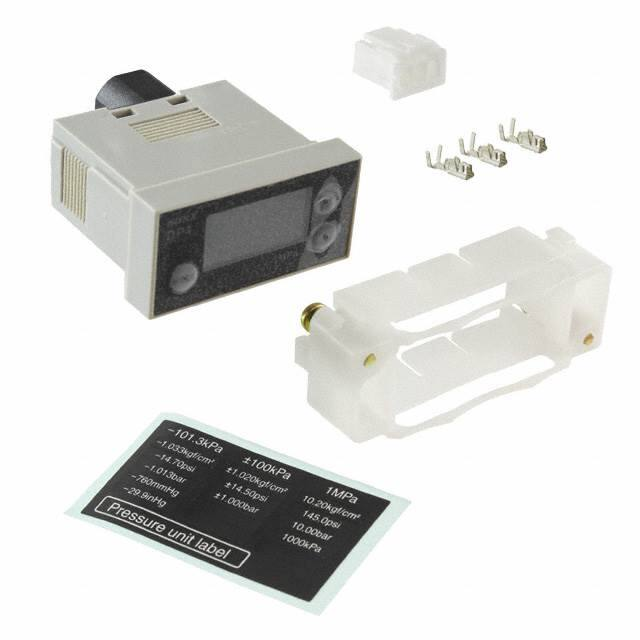
Net weight: 30 g approx.
Panel mounting bracket (MS-DP-1): 1 set, Pressure unit label: 1 pc.
Connector: 1 set (Housing: 1 pc., Connector pin: 3 pcs.)
Notes: 1) Where measurement conditions have not been specified precisely, the conditions used were an ambient temperature of +20 °C +68 °F.
2) If the wiring is longer than 5 m 16.404 ft, use a cable with a diameter of 0.3 mm2 or more.
Flow
Other
Products
DP4
�751
Compact Size Digital Pressure Sensor
I/O CIRCUIT AND WIRING DIAGRAMS
FIBER
SENSORS
LASER
SENSORS
PHOTOELECTRIC
SENSORS
DP4-5□
Color code of connector attached cable
D
3
(Brown) +V
Load
2
Tr
ZD
1
12 to 24 V DC
+10 %
–15
–
(Blue) 0 V
Internal circuit
INDUCTIVE
PROXIMITY
SENSORS
+
(Black) Output
100 mA max.
PRESSURE /
FLOW
SENSORS
PARTICULAR
USE
SENSORS
Terminal arrangement diagram
Terminal No.
Sensor circuit
LIGHT
CURTAINS
NPN output type
I/O circuit diagram
MICRO
PHOTOELECTRIC
SENSORS
AREA
SENSORS
DP4 SERIES
0V
Users’ circuit
Output
+V
Symbols … D : Reverse supply polarity protection diode
ZD: Surge absorption zener diode
Tr : NPN output transistor
SENSOR
OPTIONS
DP4-5□P
PNP output type
I/O circuit diagram
Terminal arrangement diagram
WIRE-SAVING
SYSTEMS
Terminal No.
Color code of connector attached cable
MEASUREMENT
SENSORS
ENDOSCOPE
Sensor circuit
STATIC
CONTROL
DEVICES
D
ZD
Tr
HUMAN
MACHINE
INTERFACES
ENERGY
CONSUMPTION
VISUALIZATION
COMPONENTS
FA
COMPONENTS
100 mA max.
2
+
(Black) Output
12 to 24 V DC
+10 %
–15
–
Load
1
LASER
MARKERS
PLC /
TERMINALS
3
(Brown) +V
(Blue) 0 V
Internal circuit
0V
Users’ circuit
PRECAUTIONS FOR PROPER USE
• Never use this product as a sensing device
for personnel protection.
• In case of using sensing devices for personnel
protection, use products which meet laws and
standards, such as OSHA, ANSI or IEC etc.,
for personnel protection applicable in each
region or country.
• The DP4 series is designed for use with noncorrosive gas. It cannot be used with liquid or
corrosive gas.
UV
CURING
SYSTEMS
Selection
Guide
Pressure/
Digital Display
Pressure/
Head-separated
Refer to General precautions.
Description
1
Functional description
1
Increment key
(UP)
3
Decrement
key
(DOWN)
4
• In the pressure setting mode, pressing the key
changes the setting item. In addition, if pressed for 4
sec., or more, in Set Value 1 (P-1) or Set Value 4 (P-4)
setting mode, the setting mode will change to either
Set Value 4 (P-4) or Set Value 1 (P-1) setting mode.
Mode selection
• In the sensing mode, pressing the key continuously for
key
4 sec., or more, can set / cancel the key-protect.
(MODE)
• In the sensing mode, pressing both lncrement key and
Mode selection key simultaneously changes the mode
to the initial setting mode.
Whereas, pressing both Decrement key and Mode
selection key simultaneously changes the mode to the
supplementary setting mode.
2
4
3
UP
DP4
MODE
–101.3kPa
DOWN
• In the initial setting mode and
supplementary setting mode, pressing
the key changes the setting item.
• In the pressure value setting mode,
pressing the key changes the set value.
• In the sensing mode, pressing the
key continuously for 4 sec., or more,
displays the peak hold value.
• In the initial setting mode and
supplementary setting mode, pressing
the key changes the set conditions.
• In the pressure value setting mode,
pressing the key changes the set value.
• In the sensing mode, pressing the
key continuously for 4 sec., or more,
displays the bottom hold value.
2
Operation
• If setting is impossible even with pressing the MODE
key, verify whether the key-protect function is enabled.
Please note that pressing down on the MODE key for an
extended moment will enable the key-protect function as
soon as the key is released.
• If using the window comparator mode, set the pressure
value so that there is a difference of 3 digits, or more,
between Set Value 1 (P-1) and Set Value 2 (P-2). No
output will be possible with a 0 to 2 digit difference.
Function
3 1 /2 digit LCD display Displays measured pressure, settings, error
with red and green messages and key-protect status.
Red display when output is ON.
backlight
Green display when output is OFF.
Flow
DP4
+V
Symbols … D : Reverse supply polarity protection diode
ZD: Surge absorption zener diode
Tr : PNP output transistor
MACHINE
VISION
SYSTEMS
Other
Products
Output
In the sensing mode, if both keys are
simultaneously pressed continuously,
zero-point adjustment is done.
SIMPLE
WIRE-SAVING
UNITS
�Compact Size Digital Pressure Sensor
PRECAUTIONS FOR PROPER USE
Conditions in use for CE conformity
• The DP4 series is a CE conformity product complying with
EMC Directive. The harmonized standard with regard to
immunity that applies to this product is EN 61000-6-2 and the
following condition must be met to conform to that standard.
Conditions
• The sensor should be connected less than 10 m 32.808 ft
from the power supply.
• The signal line to connect with this sensor should be less
than 30 m 98.425 ft.
Setting
• The conditions which are set are stored in an EEPROM.
Kindly note that the EEPROM has a life span and its
guaranteed life is 100,000 write operation cycles.
Forced output mode
• In the initial setting mode, if the output mode is set to the
forced output mode ( ), the output is forcibly maintained
at OFF level in the sensing mode, irrespective of Set Value
1 to 3 (P-1 to P-3).
Further, if the keys are operated as per the procedure
given below, the output can be forcibly switched either ON
or OFF without applying pressure at the pressure port. This
is convenient for an operation check of the comparative
output or for an inspection before commencing work.
The diagram below appears when the DP4-50(P) has been used to
set the display to “Digital display” ( )
UP
DP4
MODE
–101.3kPa
DOWN
• In the sensing mode, press MODE key to
change to the forced output mode.
• Whenever UP key is pressed, the output state
switches to either ON and OFF alternately.
• Press MODE key to return to the sensing mode.
• Output is kept off at the point where the mode is changed
from another output mode to forced output control mode ( ).
• Even if output has been set to stay on during forced output
control mode, it will be forcibly changed to off at the point
where the mode changes back to sensing mode.
UP
DP4
MODE
–101.3kPa
DOWN
• If the MODE key is pressed in a sensing mode
other than forced output mode, the mode will
change to pressure value setting mode.
• After releasing the MODE key, press the
MODE key again continuously until
is
displayed (4 sec. or more).
• Make the setting for Set Values 4 to 6 (P-4 to
P-6). Set Values 4 to 6 (P-4 to P-6) correspond
to Set Values 1 to 3 (P-1 to P-3) respectively.
Peak hold & bottom hold functions
• Peak hold and bottom hold functions enable the display of the
peak value (maximum pressure value) and the bottom value
(minimum pressure value) of the varying measured pressure.
These functions are convenient for finding the pressure
variation range or for determining the reference for pressure
settings.
• Please note that the peak value and the bottom value
data is erased when it is no longer displayed.
752
Refer to General precautions.
Key-protect function
• Key-protect is a function which prevents any unintentional
change in the conditions which have been entered in
each setting mode by making the sensor not to respond
to the key operations.
• Since the key-protect information is stored in an
EEPROM, it is not erased even if the power supply is
switched off.
• Please take care to remember if the key-protect
function has been set.
• When the keys are to be operated, make sure that keyprotect is released.
FIBER
SENSORS
LASER
SENSORS
PHOTOELECTRIC
SENSORS
MICRO
PHOTOELECTRIC
SENSORS
AREA
SENSORS
LIGHT
CURTAINS
PRESSURE /
FLOW
SENSORS
INDUCTIVE
PROXIMITY
SENSORS
PARTICULAR
USE
SENSORS
Piping
• When connecting a commercial M5 coupling to the
pressure port, hold the flat sides of the pressure port
with a 13 mm 0.512 in spanner and make sure that the
tightening torque is 1 N·m or less.
If excessive tightening torque is applied, the commercial
fitting may break.
13 mm 0.512 in
spanner
SENSOR
OPTIONS
SIMPLE
WIRE-SAVING
UNITS
WIRE-SAVING
SYSTEMS
MEASUREMENT
SENSORS
STATIC
CONTROL
DEVICES
ENDOSCOPE
LASER
MARKERS
PLC /
TERMINALS
Mounting
• Install the enclosed panel mounting bracket (MS-DP-1) as
shown in the figure below.
The tightening torque should be 0.15 N·m or less. Further,
tighten both the right and the left screw gradually and
equally, so that the panel mounting bracket does not tilt.
HUMAN
MACHINE
INTERFACES
ENERGY
CONSUMPTION
VISUALIZATION
COMPONENTS
FA
COMPONENTS
MACHINE
VISION
SYSTEMS
UV
CURING
SYSTEMS
M3 (length 15 mm 0.591 in)
panel fixing screw (Accessory)
Memory bank function
• The memory bank function is a function which allows two
types of output to be stored: Set Values 1 to 3 (P-1 to P-3)
and Set Values 4 to 6 (P-4 to P-6).
This make it possible to change set values quickly.
DP4 SERIES
Panel mounting bracket
(MS-DP-1)(Accessory)
Others
• Use within the rated pressure range.
• Do not apply pressure exceeding the pressure
withstandability value. The diaphragm will get damaged
and correct operation shall not be maintained.
• Do not use during the initial transient time (3 sec. approx.)
after the power supply is switched on.
• Avoid dust, dirt, and steam.
• Take care that the sensor does not come in direct contact
with water, oil, grease, or organic solvents, such as,
thinner, etc.
• Do not insert wires, etc., into the pressure port. The
diaphragm will get damaged and correct operation shall
not be maintained.
• Do not operate the keys with pointed or sharp objects.
Selection
Guide
Pressure/
Digital Display
Pressure/
Head-separated
Flow
Other
Products
DP4
�753
FIBER
SENSORS
LASER
SENSORS
Compact Size Digital Pressure Sensor
DP4 SERIES
DIMENSIONS (Unit: mm in)
The CAD data in the dimensions can be downloaded from our website.
DP4-5□(P)
PHOTOELECTRIC
SENSORS
Sensor
MICRO
PHOTOELECTRIC
SENSORS
7
0.276
40
1.575
3 1/2 digit LCD display
(Green and red)
Increment key
UP
AREA
SENSORS
MODE
LIGHT
CURTAINS
Mode selection key
DOWN
42
1.654
29
1.142
36.5
1.437
(5)
(0.197)
20
0.787
M5 female thread
Decrement key
Connector
PRESSURE /
FLOW
SENSORS
INDUCTIVE
PROXIMITY
SENSORS
PARTICULAR
USE
SENSORS
SENSOR
OPTIONS
SIMPLE
WIRE-SAVING
UNITS
MS-DP-2
DIN rail mounting bracket (Optional)
WIRE-SAVING
SYSTEMS
Assembly dimensions
MEASUREMENT
SENSORS
Variable range
STATIC
CONTROL
DEVICES
40
1.575
2
0.079
(10)
(0.394)
2-ø4.5 ø0.177
mounting holes
42
1.654
9
0.354
ENDOSCOPE
LASER
MARKERS
PLC /
TERMINALS
HUMAN
MACHINE
INTERFACES
6 0.236
20
0.787
UP
MODE
DOWN
15
0.591
49
1.929
2-ø4.5 ø0.177
mounting holes
13
0.512
20
0.787
ENERGY
CONSUMPTION
VISUALIZATION
COMPONENTS
52
40
1.575 2.047
9
0.354
40
1.575
52
2.047
Suitable for
35 mm 1.378 in
width DIN rail
3
0.118
FA
COMPONENTS
6
0.236
Variable range
(10)
(0.394)
15
0.591
13
0.512
40
1.575
MACHINE
VISION
SYSTEMS
UP
MODE
DOWN
UV
CURING
SYSTEMS
35
1.378
MS-DP-1
Selection
Guide
Pressure/
Digital Display
3
0.118
20
0.787
2.9
0.114
Panel mounting bracket (Accessory)
Assembly dimensions
Panel cut-out dimensions
56
2.205
49
1.929
40
1.575
Pressure/
Head-separated
Flow
Other
Products
DP4
Suitable for
35 mm 1.378 in
width DIN rail
(21.55) 20 13.9
(0.848) 0.787 0.547
60
2.362
+0.5
17 0
0.669 +0.020
0
UP
MODE
+0.5
DOWN
37 0
1.457 + 0.020
0
+0.5
7
0.276
42
1.654
37 0
1.457 +0.020
0
X +0.5
0
X +0.020
0
Panel fixing screw
Material: POM
Two M3 (length 15 mm 0.591 in) screws for fitting are attached.
X when “n” unit is installed
X = 20 × (n –1) + 17 mm
X = 0.787 × (n –1) + 0.669 in
Note: The panel thickness should be
1 to 6 mm 0.039 to 0.236 in.
�Compact Size Digital Pressure Sensor
DIMENSIONS (Unit: mm in)
DP4 SERIES
754
The CAD data in the dimensions can be downloaded from our website.
MS-DP-5
Panel mounting bracket (Optional)
FIBER
SENSORS
LASER
SENSORS
PHOTOELECTRIC
SENSORS
Assembly dimensions
MICRO
PHOTOELECTRIC
SENSORS
AREA
SENSORS
Panel
LIGHT
CURTAINS
7
0.276
40
1.575
PRESSURE /
FLOW
SENSORS
30
1.181
5
0.197
42
1.654
INDUCTIVE
PROXIMITY
SENSORS
PARTICULAR
USE
SENSORS
28.3
1.114
UP
35.3 20
1.390 0.787
MODE
DOWN
Applicable panel thickness
dimensions
t = 1 to 6 mm
t = 0.039 to 0.236 in
SENSOR
OPTIONS
SIMPLE
WIRE-SAVING
UNITS
Panel fixing screw
WIRE-SAVING
SYSTEMS
Panel cut-out dimensions
37 +0.5
0
1.457 +0.020
MEASUREMENT
SENSORS
+0.020
X +0.5
0
0
0
17 +0.5
0
0.669 +0.020
0
+0.5
17 0
0.669 +0.020
0
X when “n” unit is installed
X = 40 × (n – 1) + 37 mm
X = 1.575 × (n – 1) + 1.457 in
(n = 12 or less)
When installed laterally in sequence.
40
1.575
or more
Note: The panel thickness should be 1 to
6 mm 0.039 to 0.236 in.
When installing individually
MS-DP-3
Sensor mounting bracket (Optional)
MS-DP-4
Sensor mounting bracket (Optional)
19.75
0.778
12
0.472
t2
t 0.079
37
1.457
R16 R0.630
36.5
1.437
PLC /
TERMINALS
HUMAN
MACHINE
INTERFACES
ENERGY
CONSUMPTION
VISUALIZATION
COMPONENTS
t2
t 0.079
Connector (Optional)
CN-63-C2 CN-63-C5
(2.3)
(0.091)
Mating connector
Connector pin: BXA-001T-P0.6 manufactured by J.S.T
Mfg. Co., Ltd.
Housing: XAP-03V-1 manufactured by J.S.T Mfg. Co., Ltd.
Crimping tool
YC-692R manufactured by J.S.T Mfg. Co., Ltd.
Pressure/
Head-separated
Connector attached cable (Optional)
2,000 78.740
(CN-63-C5: 5,000 196.850)
(9.5)
(0.374)
(6.5)
(0.256)
Pressure/
Digital Display
4.5
0.177
Note: Use with the panel mounting bracket (MS-DP-1) included with the sensor.
(1.9)
(0.075)
(6.9)
(0.272)
ø4.5 ø0.177
mounting holes
Material: Cold rolled carbon steel (SPCC)(Nickel plated)
(5.0)
(0.197)
UV
CURING
SYSTEMS
Selection
Guide
30°
(9.8)
(0.386)
(9.5)
(0.374)
30
1.181
16
0.630
17 28
0.669 1.102 6
0.236
Note: Use with the panel mounting bracket (MS-DP-1) included with the sensor.
65
2.559
17 41
0.669 1.614
Material: Cold rolled carbon steel (SPCC)(Nickel plated)
CN-63
LASER
MARKERS
MACHINE
VISION
SYSTEMS
24
0.945
57
2.244
37
1.457
ENDOSCOPE
FA
COMPONENTS
57
2.244
40
1.575
2-ø4.5 ø0.177
mounting holes
STATIC
CONTROL
DEVICES
(8.3)
(0.327)
(5.8)
(0.228)
XAP-03V-1 manufactured by
J.S.T Mfg. Co., Ltd.
Flow
Other
Products
DP4
(50)
(1.969)
(8)
(0.315)
ø3.8 ø0.150 cable
�


 工商网监
湘ICP备2023018690号
工商网监
湘ICP备2023018690号
