1135
FIBER
SENSORS
Metal-sheet Double-feed Detector
GD SERIES
Related Information
■■General terms and conditions.............. F-3
■■General precautions........................P.1595
LASER
SENSORS
PHOTOELECTRIC
SENSORS
MICRO
PHOTOELECTRIC
SENSORS
AREA
SENSORS
SAFETY LIGHT
CURTAINS /
SAFETY COMPONENTS
PRESSURE /
FLOW
SENSORS
INDUCTIVE
PROXIMITY
SENSORS
PARTICULAR
USE SENSORS
SENSOR
OPTIONS
SIMPLE
WIRE-SAVING
UNITS
WIRE-SAVING
SYSTEMS
MEASUREMENT
SENSORS
STATIC
CONTROL
DEVICES
LASER
MARKERS
PLC
HUMAN MACHINE
INTERFACES
ENERGY
MANAGEMENT
SOLUTIONS
FA COMPONENTS
panasonic.net/id/pidsx/global
From ultra-thin lead frames to iron sheets...
Double feed detection of various metal sheets
Double metal sheets detected
The high-end GD sensing technology detects double feeds of any
metal sheet 0.01 mm 0.0004 in, or more, thick.
MACHINE VISION
SYSTEMS
UV CURING
SYSTEMS
Easy sensitivity setting with actual samples
Optimum sensitivity setting is easy by using the teaching function with actual samples.
Selection
Guide
Laser
Displacement
Magnetic
Displacement
Contact
Displacement
Collimated
Beam Sensors
Metal-sheet
Double-feed Detection
Digital Panel
Controller
Other Products
GD
1 Press the “0-ADJ. key” while no object exists
between sensor heads.
2 Place one sheet between the sensor heads
and press the “SET-1 key”.
3 Place two sheets between the sensor heads
and press the “SET-2 key”.
VARIETIES
Three types of sensor heads for various objects
Small object detection sensor head / GD-3
This is an extremely small sensor
head, only ø3.8 × 15 mm ø0.150 ×
0.591 in, suitable for detecting small
components.
15 mm
0.591 in
ø3.8 mm
ø0.150 in
High precision sensor head / GD-10
It is suitable for high precision
detection of double feeds of lead
frames or thin metal sheets.
32.2 mm
1.268 in
12 mm
0.472 in
7.1 mm
0.280 in
Long sensing range sensor head / GD-20
It achieves a long sensing range of 70 mm 2.756 in.
Further, it employs a robust metal case with IP67G
protection to withstand harsh environment.
Sensing range
70 mm
2.756 in
�Metal-sheet Double-feed Detector
GD SERIES
APPLICATIONS
1136
FIBER
SENSORS
Detecting overlap of washers
Detecting double feeds of lead frames
GD-3 detects an overlap of small
components such as washers.
The high precision sensor head GD-10
does not miss double feeds of lead
frames even if they are very thin and
highly perforated.
Detecting double feeds of sheet metal
The long sensing range sensor head
GD-20 allows the object thickness to
be as much as 10 mm 0.394 in. Hence,
various objects can be detected.
LASER
SENSORS
PHOTOELECTRIC
SENSORS
MICRO
PHOTOELECTRIC
SENSORS
AREA
SENSORS
GD-3
GD-10
Detecting seam of hoop material
Even a minute difference in thickness
can be detected.
SAFETY LIGHT
CURTAINS /
SAFETY COMPONENTS
PRESSURE /
FLOW
SENSORS
INDUCTIVE
PROXIMITY
SENSORS
GD-20
Detecting double feeds of aluminum foils
GD-10 can detect double feeds of thin
aluminum foils which are several tens
of micrometer thick.
Detecting missing tablet package in box
GD-20 can check if each box contains a given
number of aluminum tablet packages.
Since GD-20 has a sensing range of up to 70 mm
2.756 in, thick boxes can pass
through the sensor heads.
PARTICULAR
USE SENSORS
SENSOR
OPTIONS
SIMPLE
WIRE-SAVING
UNITS
WIRE-SAVING
SYSTEMS
MEASUREMENT
SENSORS
GD-3
GD-10
Tablet packages
GD-20
LASER
MARKERS
PLC
FUNCTIONS
HUMAN MACHINE
INTERFACES
Seven LEDs indicate the sensing level
Suitable for flexible manufacturing
The optimum
sensing point can
be confirmed at a
glance as seven
LEDs indicate the
sensing level.
Since sensitivities of eight channels can be stored, product
changeover is smooth and easy.
Select channel number by the “Channel shift key” on the
operation panel or by using external channel select inputs.
Further, since GD-C2 is equipped with RS-232C
communication function, the sensitivity values can be
stored in a personal computer, etc., and fed into the
controller as per requirement.
One-sheet level
Sensing level indicators
Two-sheet level
2
3
Article A
Article B
Article C
GD-C2
IN-0
IN-1
IN-2
0V
1
Two-sheet threshold level shift function
RS-232C
External channel select inputs
Two-sheet
threshold level
Two-sheet level
FA COMPONENTS
MACHINE VISION
SYSTEMS
UV CURING
SYSTEMS
Selection
Guide
Laser
Displacement
Magnetic
Displacement
Contact
Displacement
Collimated
Beam Sensors
Metal-sheet
Double-feed Detection
Digital Panel
Controller
Other Products
(0%)
1 (10%)
2 (20%)
3 (30%)
4 (40%)
5 (50%)
6 (60%)
7 (70%)
8 (80%)
9 (90%)
(100%)
In normal teaching, the two-sheet
threshold level is set at 5 (50 %).
External initialization
Teaching is possible
by external devices,
such as, PLC, etc.
This enhances
productivity by
machine automation.
GD
External setting inputs
RUN / SET
SET-1
SET-2
One-sheet level
Two-sheet threshold
level indication
ENERGY
MANAGEMENT
SOLUTIONS
Channel
display
Channel
shift key
The two-sheet
threshold level set
by teaching can be
shifted in nine steps
to suit the detection
conditions. This
enables very stable
detection.
STATIC
CONTROL
DEVICES
�1137
LASER
SENSORS
PHOTOELECTRIC
SENSORS
MICRO
PHOTOELECTRIC
SENSORS
AREA
SENSORS
SAFETY LIGHT
CURTAINS /
SAFETY
COMPONENTS
PRESSURE /
FLOW
SENSORS
GD SERIES
ORDER GUIDE
Sensor heads
Type
Appearance
Sensing range
(between sensor heads)
10 mm 0.394 in
High precision
30 mm 1.181 in
MACHINE
VISION
SYSTEMS
UV
CURING
SYSTEMS
Brass
0.03 to 1 mm 0.001 to 0.039 in 0.03 to 0.5 mm 0.001 to 0.020 in
Aluminum
Copper
Brass
20 mm 0.787 in
GD-3
GD-C3
GD-10
GD-C1
GD-C2
GD-C3
GD-20
GD-C1
GD-C2
30 mm 1.181 in
0.07 to 1 mm 0.003 to 0.039 in 0.07 to 0.5 mm 0.003 to 0.020 in
0.01 to 0.3 mm 0.0004 to 0.012 in 0.01 to 0.1 mm 0.0004 to 0.004 in
GD-C1/C2
0.03 to 6 mm 0.001 to 0.236 in 0.03 to 2 mm 0.001 to 0.079 in
GD-C3
0.015 to 1 mm 0.001 to 0.039 in 0.015 to 1 mm 0.001 to 0.039 in
GD-C1/C2
0.03 to 6 mm 0.001 to 0.236 in 0.03 to 2 mm 0.001 to 0.079 in
GD-C3
0.018 to 1 mm 0.001 to 0.039 in 0.018 to 1 mm 0.001 to 0.039 in
GD-C1/C2
0.03 to 6 mm 0.001 to 0.236 in 0.03 to 2 mm 0.001 to 0.079 in
GD-C3
0.01 to 1 mm 0.0004 to 0.039 in 0.01 to 1 mm 0.0004 to 0.039 in
Stainless steel GD-C1/C2
(SUS304)
GD-C3
PLC
0.1 to 6 mm 0.004 to 0.236 in 0.1 to 2 mm 0.004 to 0.079 in
0.05 to 2 mm 0.002 to 0.079 in 0.05 to 1 mm 0.002 to 0.039 in
Standard sensing object size: 200 × 200 mm 7.874 × 7.874 in
Long sensing range
FA
COMPONENTS
0.018 to 1 mm 0.001 to 0.039 in 0.018 to 0.3 mm 0.001 to 0.012 in
GD-C1/C2
Iron
(SPCC) GD-C3
LASER
MARKERS
ENERGY
MANAGEMENT
SOLUTIONS
0.015 to 1 mm 0.001 to 0.039 in 0.015 to 1 mm 0.001 to 0.039 in
Copper
Setting distance
Applicable
Material
controllers
STATIC
CONTROL
DEVICES
HUMAN
MACHINE
INTERFACES
Aluminum
Standard sensing object size: 80 × 80 mm 3.150 × 3.150 in
SENSOR
OPTIONS
MEASUREMENT
SENSORS
Applicable
controllers
Stainless steel (SUS304) 0.3 to 1 mm 0.012 to 0.039 in 0.3 to 1 mm 0.012 to 0.039 in
PARTICULAR
USE
SENSORS
WIRE-SAVING
SYSTEMS
Model No.
Setting distance
5 mm 0.197 in
10 mm 0.394 in
Material
Iron (SPCC)
0.01 to 0.1 mm 0.0004 to 0.004 in 0.03 to 0.1 mm 0.001 to 0.004 in
INDUCTIVE
PROXIMITY
SENSORS
SIMPLE
WIRE-SAVING
UNITS
Detectable sheet thickness
Standard sensing object size: 20 × 20 mm 0.787 × 0.787 in
Small object detection
FIBER
SENSORS
Metal-sheet Double-feed Detector
70 mm
2.756 in
Setting distance 35 mm 1.378 in
70 mm 2.756 in
Material
Iron (SPCC)
0.07 to 10 mm 0.003 to 0.394 in 0.07 to 6 mm 0.003 to 0.236 in
Aluminum
0.03 to 10 mm 0.001 to 0.394 in 0.03 to 6 mm 0.001 to 0.236 in
Copper
0.03 to 10 mm 0.001 to 0.394 in 0.03 to 6 mm 0.001 to 0.236 in
Brass
0.03 to 10 mm 0.001 to 0.394 in 0.03 to 6 mm 0.001 to 0.236 in
Stainless steel (SUS304) 0.1 to 10 mm 0.004 to 0.394 in 0.1 to 6 mm 0.004 to 0.236 in
Note: �Only the combinations between the sensor heads and the controllers described in the above table are allowed. Any other combination may damage the
connected sensor heads.
10 m 32.808 ft cable length type and 20 m 65.617 ft cable length type
10 m 32.808 ft cable length type and 20 m 65.617 ft cable length type for GD-20 are also available. (Standard: 3 m 9.843 ft)
Selection
Guide
Laser
Displacement
Magnetic
Displacement
Contact
Displacement
Collimated
Beam
Sensors
Metal-sheet
Double-feed
Detection
Type
Long sensing
range
Standard
GD-20
10 m 32.808 ft cable length type 20 m 65.617 ft cable length type
GD-20-C10
GD-20-C20
Controllers
Type
Appearance
Model No.
Output
Standard
GD
GD-C1
With
RS-232C
Other
Products
GD-C2
Small object
detection
Digital Panel
Controller
GD-C3
NPN open-collector transistor
Make sure to use the sensor heads
and the controller together in the
above combinations.
�Metal-sheet Double-feed Detector
GD SERIES
1138
SPECIFICATIONS
FIBER
SENSORS
LASER
SENSORS
Sensor heads
Type
Model No.
Item
Environmental resistance
Applicable controllers
Sensing range (between sensor heads)
Detectable sheet thickness (Note 2)
Setting distance
Applicable
controllers
Material
GD-C1/C2
Iron
(SPCC)
GD-C3
GD-C1/C2
Aluminum
GD-C3
GD-C1/C2
Copper
GD-C3
GD-C1/C2
Brass
GD-C3
Stainless steel GD-C1/C2
(SUS304) GD-C3
Protection
Ambient temperature
Ambient humidity
Vibration resistance
Shock resistance
Material
Cable
Cable extension
Weight
Accessory
Small object detection
GD-3
High precision
GD-10
Long sensing range
GD-20
GD-C3
10 mm 0.394 in or less
Standard sensing object size: 20 × 20 mm 0.787 × 0.787 in
GD-C1, GD-C2, GD-C3
30 mm 1.181 in or less
Standard sensing object size: 80 × 80 mm 3.150 × 3.150 in
GD-C1, GD-C2
70 mm 2.756 in or less
Standard sensing object size: 200 × 200 mm 7.874 × 7.874 in
5 mm 0.197 in
10 mm 0.394 in
20 mm 0.787 in
30 mm 1.181 in
35 mm 1.378 in
70 mm 2.756 in
–
0.01 to 0.1 mm 0.0004 to 0.004 in
–
0.015 to 1 mm 0.001 to 0.039 in
–
0.018 to 1 mm 0.001 to 0.039 in
–
0.03 to 1 mm 0.001 to 0.039 in
–
0.3 to 1 mm 0.012 to 0.039 in
–
0.07 to 1 mm 0.003 to 0.039 in 0.07 to 0.5 mm 0.003 to 0.020 in 0.07 to 10 mm 0.003 to 0.394 in 0.07 to 6 mm 0.003 to 0.236 in
–
–
0.03 to 0.1 mm 0.001 to 0.004 in 0.01 to 0.3 mm 0.0004 to 0.012 in 0.01 to 0.1 mm 0.0004 to 0.004 in
–
0.03 to 6 mm 0.001 to 0.236 in 0.03 to 2 mm 0.001 to 0.079 in 0.03 to 10 mm 0.001 to 0.394 in 0.03 to 6 mm 0.001 to 0.236 in
–
–
0.015 to 1 mm 0.001 to 0.039 in 0.015 to 1 mm 0.001 to 0.039 in 0.015 to 1 mm 0.001 to 0.039 in
–
0.03 to 6 mm 0.001 to 0.236 in 0.03 to 2 mm 0.001 to 0.079 in 0.03 to 10 mm 0.001 to 0.394 in 0.03 to 6 mm 0.001 to 0.236 in
–
–
0.018 to 0.3 mm 0.001 to 0.012 in 0.018 to 1 mm 0.001 to 0.039 in 0.018 to 1 mm 0.001 to 0.039 in
–
0.03 to 6 mm 0.001 to 0.236 in 0.03 to 2 mm 0.001 to 0.079 in 0.03 to 10 mm 0.001 to 0.394 in 0.03 to 6 mm 0.001 to 0.236 in
–
–
0.03 to 0.5 mm 0.001 to 0.020 in 0.01 to 1 mm 0.0004 to 0.039 in 0.01 to 1 mm 0.0004 to 0.039 in
–
0.1 to 6 mm 0.004 to 0.236 in 0.1 to 2 mm 0.004 to 0.079 in 0.1 to 10 mm 0.004 to 0.394 in 0.1 to 6 mm 0.004 to 0.236 in
–
–
0.3 to 1 mm 0.012 to 0.039 in 0.05 to 2 mm 0.002 to 0.079 in 0.05 to 1 mm 0.002 to 0.039 in
IP67 (IEC)
IP67 (IEC), IP67G
–10 to +60 °C +14 to +140 °F, Storage: –25 to +70 °C –13 to +158 °F
45 to 85 % RH, Storage: 35 to 95 % RH
10 to 55 Hz frequency, 1.5 mm 0.059 in double amplitude in X, Y and Z directions for two hours each
1,000 m/s2 acceleration (100 G approx.) in X, Y and Z directions three times each
Enclosure: Stainless steel (SUS303), Sensing face: ABS
Enclosure: Polyalylate
Sensing face: Polyacetal, Main body: Stainless steel
Sender: 0.5 mm2 single core shielded cable, 3 m 9.843 ft long
Sender: 0.3 mm2 single core shielded cable, 3 m 9.843 ft long
Receiver: 0.3 mm2 2-core shielded cable, 3 m 9.843 ft long
Receiver: 0.1 mm2 2-core shielded cable, 3 m 9.843 ft long
Extension up to total 20 m 65.617 ft is possible with an equivalent shielded cable.
Net weight: 90 g approx.
Net weight: 80 g approx.
Net weight: 440 g approx.
–
–
Sensor head mounting bracket: 1 set for sender and receiver
Notes: 1) Where measurement conditions have not been specified precisely, the conditions used were an ambient temperature of +20 °C +68 °F.
2) �The above detectable sheet thicknesses are typical data at the given sensing distance. The allowable thickness will differ from the range described in
the above table at other setting distances. Further, double feeds of aluminum foils can also be detected at distances shorter than the above.
Please contact our office for details.
Controllers
Type
Item
Model No.
Supply voltage
Current consumption
Outputs
OUT-1, OUT-2, ALM.
Answer-back
Standard
GD-C1
With RS-232C communication function
GD-C2
Small object detection
GD-C3
12 to 24 V DC ±10 % Ripple P-P 10 % or less
12 V DC: 700 mA or less, 24 V DC: 400 mA or less
NPN open-collector transistor
• Maximum sink current: 100 mA
• Applied voltage: 30 V DC or less (between output and 0 V)
• Residual voltage: �1 V or less (at 100 mA sink current)�
0.4 V or less (at 16 mA sink current)
Environmental resistance
Indicators
Output operation
OUT-1
OFF above the one-sheet threshold level
OUT-2
OFF above the two-sheet threshold level
A L M.
OFF when an error occurs
Answer-back (ANS. OUT)
Refer to the time chart of the “Sensitivity setting of PRECAUTIONS FOR PROPER USE” (p.1141)
Short-circuit protection
Incorporated
Automatically selected either 5 ms or less, or 30 ms or less, depending on the object
5 ms or less
Response time
Set level storage function
Set values of eight channels stored
Set level teaching function
Incorporated
External setting function
Incorporated
Power
Green LED (lights up when the power is ON)
Self-diagnosis (ALM.)
Red LED (lights up during SET mode and when an error occurs during RUN mode)
Sensing mode (SENSE)
2-color indicator (lights up green during normal sensing mode, but yellow during precise sensing mode)
Comparative output-1 (OUT-1)
Green LED (lights up when OUT-1 is OFF, and blinks twice on completion of 0-ADJ. or SET-1 setting in SET mode)
Comparative output-2 (OUT-2)
Red LED (lights up when OUT-2 is OFF, and blinks twice on completion of 0-ADJ. or SET-2 setting in SET mode)
Sensing level
Yellow LED × 1 and green LED × 6 (indicate the sensing level)
Timer function
Approx. 50 ms fixed delay timer (switchable either effective or ineffective)
Ambient temperature
–10 to +50 °C +14 to +122 °F (No dew condensation or icing allowed), Storage: –25 to +70 C° –13 to +158 °F
Ambient humidity
45 to 85 % RH, Storage: 35 to 90 % RH
Voltage withstandability
1,000 V AC for one min. between all supply terminals connected together and enclosure
Insulation resistance
50 MΩ, or more, with 250 V DC megger between all supply terminals connected together and enclosure
Vibration resistance
10 to 55 Hz frequency, 0.75 mm 0.030 in double amplitude in X, Y and Z directions for two hours each
Shock resistance
300 m/s2 acceleration (30 G approx.) in X, Y and Z directions three times each
Material
Heat-resistant ABS
Weight
Net weight: 440 g approx.
Accessory
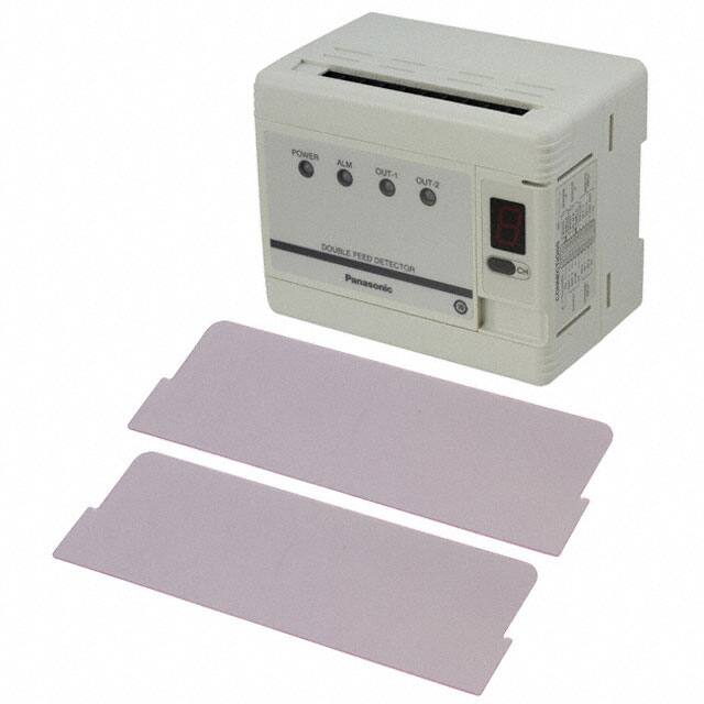
Insulation plate: 2 pcs.
Note: Where measurement conditions have not been specified precisely, the conditions used were an ambient temperature of +20 °C +68 °F.
PHOTOELECTRIC
SENSORS
MICRO
PHOTOELECTRIC
SENSORS
AREA
SENSORS
SAFETY LIGHT
CURTAINS /
SAFETY
COMPONENTS
PRESSURE /
FLOW
SENSORS
INDUCTIVE
PROXIMITY
SENSORS
PARTICULAR
USE
SENSORS
SENSOR
OPTIONS
SIMPLE
WIRE-SAVING
UNITS
WIRE-SAVING
SYSTEMS
MEASUREMENT
SENSORS
STATIC
CONTROL
DEVICES
LASER
MARKERS
PLC
HUMAN
MACHINE
INTERFACES
ENERGY
MANAGEMENT
SOLUTIONS
FA
COMPONENTS
MACHINE
VISION
SYSTEMS
UV
CURING
SYSTEMS
Selection
Guide
Laser
Displacement
Magnetic
Displacement
Contact
Displacement
Collimated
Beam
Sensors
Metal-sheet
Double-feed
Detection
Digital Panel
Controller
Other
Products
GD
�1139
I/O CIRCUIT AND WIRING DIAGRAMS
FIBER
SENSORS
Wiring diagram
Sender
PHOTOELECTRIC
SENSORS
MICRO
PHOTOELECTRIC
SENSORS
Color code
12 to 24 V DC ±10 %
+
AREA
SENSORS
–
Load
SAFETY LIGHT
CURTAINS /
SAFETY
COMPONENTS
INDUCTIVE
PROXIMITY
SENSORS
PARTICULAR
USE
SENSORS
SENSOR
OPTIONS
*1
or
4
13
5
14
6
15
7
16
8
17
9
18
10
19
I/O circuit diagram
30 V DC +
or less –
Input
12 to 24 V DC
+
0 V (Note) –
±10 %
Load
OUT-1, OUT-2, ALM.,
Output Answer-back
Sensor circuit
D
Tr
ZD
FA
COMPONENTS
Internal circuit
+
30 V DC
or less
–
100 mA max.
0 V (Note)
*1
Input
IN-0, IN-1, IN-2,
RUN / SET, SET-1, SET-2
Users’ circuit
Note: �0 V of power supply is isolated from 0 V of input/output circuitry. To
share the power supply with a load, both the 0 V terminals should be
short-circuited.
RS-232C wiring diagram (GD-C2 only)
Other
Products
Controller
Digital Panel
Controller
TXD (3)
TXD
RXD (2)
RXD
RS (7)
RS
CS (8)
CS
SG (5)
SG
External device
Connector pin No.
Contact
Displacement
Collimated
Beam
Sensors
Metal-sheet
Double-feed
Detection
*1
IN-1
IN-2
1
L
H
H
2
H
L
H
3
L
L
H
4
H
H
L
5
L
H
L
6
H
L
L
7
L
L
L
8
H
H
H
L: Low (0 to 1 V), H: High (4.5 to 30 V, or open)
Selection
Guide
Magnetic
Displacement
*1
IN-0
Channel No.
Symbols … D : Reverse supply polarity protection diode
ZD : Surge absorption zener diode
Tr : NPN output transistor
Laser
Displacement
White
Shield
White
Black
Shield
RUN / SET
SET-1
SET-2
ANS. OUT (Answer-back output) *1
0 V (Note)
Load
External channel select truth table
+V
PLC
UV
CURING
SYSTEMS
12
Low : 0 to 1 V
High: 4.5 to 30 V, or open
STATIC
CONTROL
DEVICES
MACHINE
VISION
SYSTEMS
11
3
Note: Terminal 2 , 0 V of power supply, is isolated from 0 V of input/output circuitry for
noise immunity. However, if you expect to share the power supply with the output
loads, connect terminals 2 and 6 , terminals 2 and 10 , or terminals 2 and 20 to
make 0 V common.
Non-voltage contact or
NPN open-collector transistor
MEASUREMENT
SENSORS
2
20
WIRE-SAVING
SYSTEMS
ENERGY
MANAGEMENT
SOLUTIONS
1
* 1
SIMPLE
WIRE-SAVING
UNITS
HUMAN
MACHINE
INTERFACES
+V
0 V (Note)
OUT-1 (Comparative output-1)
OUT-2 (Comparative output-2)
ALM. (Self-diagnosis output)
Load
+ – 0 V (Note)
30 V DC or less
IN-0
IN-1
IN-2
*1 0 V (Note)
*1
CH
External channel select inputs
Load
PRESSURE /
FLOW
SENSORS
LASER
MARKERS
Receiver
External setting inputs
LASER
SENSORS
GD SERIES
Metal-sheet Double-feed Detector
TXD : Transmit data, command
RXD: Receive data, command
RS : Request-to-send
CS : Clear-to-send
SG : Signal ground
GD
Pin arrangement
TXD
Not connected
SG
RXD
Not connected
3
4
5
9
8
2
7
1
6
Not connected
Not connected
CS
RS
9-pin connector (female)
�Metal-sheet Double-feed Detector
PRECAUTIONS FOR PROPER USE
• Never use this product as a sensing device
for personnel protection.
• In case of using sensing devices for
personnel protection, use products which
meet laws and standards, such as OSHA,
ANSI or IEC etc., for personnel protection
applicable in each region or country.
• Make sure to use the sensor heads and
controllers in the specified combinations. If
they are used in any other combination, the
sensor heads may get damaged.
Mounting
Placing of sensor heads
• Make the sender and receiver face each other and align
their sensing center line.
• Keep a distance from any magnet or a device generating
magnetic field. It may degrade the detectability.
• Surrounding metal influences the detectability. Please
contact our office for more details.
• If more than one set of sensor heads are closely
mounted, detectability may be affected. Please contact
our office for more details.
GD SERIES
Refer to p.1595 for general precautions.
1
2
Stopper
With the stopper pressed in the
direction of the arrow (it locks), fit
the front portion of the mounting
section of the amplifier on the
35 mm 1.378 in width DIN rail.
Press and fit the rear portion of
the mounting section on the
35 mm 1.378 in width DIN rail.
2
35 mm 1.378 in
width DIN rail
“Minus” screwdriver
1
Stopper
* �To remove, insert a “minus”
screwdriver into the stopper
and pull out.
( Purchase
separately. )
2 mm 0.079 in or more
• Use a set screw (M3 or less), and the tightening torque
should be 0.12 N·m or less.
Fixing at one point
Fixing at two points
M3 (length 12 mm 0.472 in)
pan head screw
(Accessory for GD-10)
Anti-slip
rubber washer
(Accessory for GD-10)
M3 × 0.5 mm 0.020 in
tapped hole, 10 mm 0.394 in
or more deep, or ø3.4 mm
ø0.134 in thru-hole
Nut
Purchase
separately.
)
Sensing mode
• The GD series has two sensing modes, one is the normal
sensing mode and the other is the precise sensing mode.
They are automatically selected by the characteristics of
the object.
(
If mounting using
nut and washers
Accessories
for GD-10
)
(
)
MEASUREMENT
SENSORS
STATIC
CONTROL
DEVICES
LASER
MARKERS
PLC
HUMAN
MACHINE
INTERFACES
ENERGY
MANAGEMENT
SOLUTIONS
FA
COMPONENTS
the number of objects (e.g., lead frames)
is difficult to distinguish. In this mode, the
sensitivity difference is so minute between
two sensing levels that vibration and
temperature changes must be carefully
managed.
• The sensing mode indicator lights up green during the
normal sensing mode, but lights up yellow during the
precise sensing mode.
MACHINE
VISION
SYSTEMS
UV
CURING
SYSTEMS
Selection
Guide
Laser
Displacement
Magnetic
Displacement
M3 (length 12 mm 0.472 in)
pan head screw
(Accessory for GD-10)
Mounting bracket
(Accessory for GD-10)
M3 × 0.5 mm 0.020 in
tapped hole, 10 mm 0.394 in
or more deep, or ø3.4 mm
ø0.134 in thru-hole
16 mm
0.630 in
If mounting using
nut and washers
Accessories
for GD-10
ø2.5 mm ø0.098 in hole, 3 mm 0.118 in
or more deep
SENSOR
OPTIONS
WIRE-SAVING
SYSTEMS
(
Lead frame etc.
PRESSURE /
FLOW
SENSORS
SIMPLE
WIRE-SAVING
UNITS
Precise sensing mode: �The GD series goes into this mode when
4 mm 0.157 in or more
AREA
SENSORS
PARTICULAR
USE
SENSORS
Iron etc.
Mounting with set screw
MICRO
PHOTOELECTRIC
SENSORS
INDUCTIVE
PROXIMITY
SENSORS
Two M4 pan head screws
10 mm 0.394 in, or more, long
• Use two M4 pan head
screws 10 mm 0.394 in, or
more, long. The tightening
torque should be 1.2 N·m
or less.
PHOTOELECTRIC
SENSORS
SAFETY LIGHT
CURTAINS /
SAFETY
COMPONENTS
number of objects (e.g., large metal sheets) is
distinguished with relative ease.
FIBER
SENSORS
LASER
SENSORS
Mounting of controller
Normal sensing mode: �The GD series goes into this mode when the
Mounting sensor heads
Set screw
(M3 or less)
1140
M8 mounting
hole, 6 mm
0.236 in deep
Contact
Displacement
Collimated
Beam
Sensors
Metal-sheet
Double-feed
Detection
Digital Panel
Controller
Other
Products
M8 screw
(Purchase
separately. )
• The tightening torque should be 0.5
• The tightening
N·m or less.
torque should be
11.2 N·m or less.
• To mount the sensor head with a
nut, the thru-hole should be ø3.4
mm ø0.134 in.
The mounting board must be 2.3 mm
0.091 in, or less, thick.
GD
�1141
FIBER
SENSORS
LASER
SENSORS
PHOTOELECTRIC
SENSORS
MICRO
PHOTOELECTRIC
SENSORS
AREA
SENSORS
Metal-sheet Double-feed Detector
PRECAUTIONS FOR PROPER USE
Teaching by external input
SET-1 input
RUN
Answer-back
output
(ANS. OUT)
SET-2 input
SENSOR
OPTIONS
Answer-back
output
(ANS. OUT)
STATIC
CONTROL
DEVICES
LASER
MARKERS
High
Low
SET
50 ms or more
High
Low
50 ms or more
PARTICULAR
USE
SENSORS
MEASUREMENT
SENSORS
In case the sender and another sensor’s receiver are placed adjacently
Time chart
PRESSURE /
FLOW
SENSORS
WIRE-SAVING
SYSTEMS
Interference prevention
• When two or more sensor heads are mounted in parallel,
keep a minimum separation distance as specified below
to avoid interference.
• The teaching can also be performed by external input
signals.
RUN / SET
select input
SIMPLE
WIRE-SAVING
UNITS
Refer to p.1595 for general precautions.
Sensitivity setting
SAFETY LIGHT
CURTAINS /
SAFETY
COMPONENTS
INDUCTIVE
PROXIMITY
SENSORS
GD SERIES
1 ms
or less
High
Low
CPU processTeaching successful
ing time (a few seconds)
50 ms or more
50 ms or more
High
Low
Teaching not successful
High
CPU processLow
ing time (a few seconds) Teaching successful
1 ms or less
• As metals near the sensor head may affect the sensing
performance, pay attention to the following points.
Influence of nearby metal
• The sensor head must be separated from nearby metal
by a minimum distance as specified in the table below.
Nearby metal
Nearby metal
A
A
Nearby metal
MACHINE
VISION
SYSTEMS
UV
CURING
SYSTEMS
GD-3
GD-10
GD-20
Dimension A (in case of iron)
Setting distance
Model No.
5 mm
0.197 in
15 mm
0.591 in
GD-3
GD-10
GD-20
10 mm
0.394 in
30 mm
1.181 in
70 mm
2.756 in
20 mm
–
0.787 in
100 mm 3.937 in
–
–
100 mm 3.937 in
Embedding in metal
Selection
Guide
Laser
Displacement
Magnetic
Displacement
• The sensing performance may be affected if the sensor
is completely embedded in a metal. Keep a minimum
clearance between the sensor head and the metal as
specified in the table below.
Contact
Displacement
Collimated
Beam
Sensors
Metal-sheet
Double-feed
Detection
5 mm
0.197 in
B
Other
Products
GD
Metal
Metal
Metal
GD-3
GD-10
GD-20
Dimension B (in case of iron)
Setting distance
Model No.
GD-3
GD-10
GD-20
5 mm
0.197 in
10 mm
0.394 in
30 (70) mm
1.181 (2.756) in
–
220 mm 8.661 in
630 mm 24.803 in
Note: The value in the brackets is for GD-20.
In case the respective senders and receivers are placed adjacently
D
Sender
Receiver
Sender
Receiver
Dimension D
Setting distance
5 mm
10 mm 20 (35) mm
0.394 in 0.787 (1.378) in
Model No. (Note) 0.197 in
–
30 mm 1.181 in 50 mm 1.969 in
GD-3
200 mm 7.874 in
GD-10
450 mm 17.717 in
GD-20
30 (70) mm
1.181 (2.756) in
–
250 mm 9.843 in
700 mm 27.559 in
30 mm
1.181 in
70 mm
2.756 in
ø15 mm
ø20 mm
–
ø0.591 in
ø0.787 in
ø100 mm ø3.937 in
–
ø300 mm ø11.811 in
• GD-C2 can feed in the set level data into a PC or PLC
memory using RS-232C serial communication and
retrieve it whenever required.
In this case, the taught data should be stored in the
prescribed channel.
Transmission specifications
• Baud rate: S
� electable from 300, 600, 1,200, 2,400, 4,800,
9,600, 19,200, or 31,250 bits/sec.
7 bits or 8 bits
• Format: D
� ata bits
Parity check None or Enable, Even or Odd
Stop bits
1 bit or 2 bits
Terminal code CR or ETX
Self-diagnosis (Alarm) function
• The GD series constantly runs self-diagnosis, outputs
the result with self-diagnosis output, and lights the selfdiagnosis indicator. In addition, error content is shown on
the channel display using error codes.
Others
B
B
Digital Panel
Controller
Sender
RS-232C data transmission (GD-C2 only)
HUMAN
MACHINE
INTERFACES
ENERGY
MANAGEMENT
SOLUTIONS
Receiver
Note: The value in the brackets is for GD-20.
A
A
Receiver
Dimension C
Setting distance
5 mm
10 mm 20 (35) mm
0.394 in 0.787 (1.378) in
Model No. (Note) 0.197 in
–
60 mm 2.362 in 80 mm 3.150 in
GD-3
160 mm 6.299 in
GD-10
370 mm 14.567 in
GD-20
Distance from nearby metals
PLC
FA
COMPONENTS
C
Sender
–
• Do not operate the sensor for a few seconds immediately
after supplying power because of transient conditions
including self-diagnosis time.
• Make sure to check the ability of the sensor to detect
the number of sheets of your actual objects before use.
If real objects differ from teaching samples in size or
in characteristics, or the detecting condition deviates,
an error may occur. Please note that magnetic metals
or metals with low magnetic permeability such as steel
especially have a strong tendency.
• In situations when magnets are in close proximity such
as during electromagnet conveyance, this causes
malfunctions due to electromagnetic disorder.
• When conducting minute detections, favorable sensing
conditions are obtained only after having elapsed 60 min.
after the initial introduction of the power supply.
�Metal-sheet Double-feed Detector
DIMENSIONS (Unit: mm in)
GD-3
GD SERIES
1142
The CAD data can be downloaded from our website.
Sensor head
GD-10
Sensor head
FIBER
SENSORS
LASER
SENSORS
PHOTOELECTRIC
SENSORS
MICRO
PHOTOELECTRIC
SENSORS
11.2
0.441
15 0.591
13.8 0.543
ø3.8
ø0.150
12
0.472
ø6 ø0.236 screw seat,
1.4 0.055 deep
ø3 ø0.118 shielded cable,
3 m 9.843 ft long
SAFETY LIGHT
CURTAINS /
SAFETY
COMPONENTS
6.2
0.244
6.2
0.244
22.2
0.874 27.4 32.2
1.079
1.268
11.6 0.457
ø3.5
ø0.138
AREA
SENSORS
7.1
0.280
PRESSURE /
FLOW
SENSORS
INDUCTIVE
PROXIMITY
SENSORS
ø3.2 ø0.126 mounting hole
5.8
0.228
7.5
0.295
PARTICULAR
USE
SENSORS
2.9
0.114
ø3 ø0.118 shielded
cable, 3 m 9.843 ft long
SENSOR
OPTIONS
SIMPLE
WIRE-SAVING
UNITS
GD-20
Sensor head
GD-C1 GD-C2 GD-C3
Controller
WIRE-SAVING
SYSTEMS
MEASUREMENT
SENSORS
30
1.181
22
0.866
POWER
ALM.
OUT-1
CH
DOUBLE FEED DETECTOR
ø27
ø1.063
32
1.260
STATIC
CONTROL
DEVICES
OUT-2
90
3.543
LASER
MARKERS
PLC
110
4.331
1.7
0.067
HUMAN
MACHINE
INTERFACES
Terminal cover removed
and panel cover opened
M8 hole,
6 0.236 deep
(Mounting part)
186.8 7.354
96 3.780
2-ø5 ø0.197
7 0.276 high
from bottom
143.8
5.661
13.75
0.541
ø4.5 ø0.177 shielded cable,
3 m 9.843 ft long
67
2.638
11
12
13
POWER
57
2.244
ALM.
14
15
OUT-1
17
16
ENERGY
MANAGEMENT
SOLUTIONS
FA
COMPONENTS
19
18
20
OUT-2
CH-SELECT
PANEL
RS232C
SENS.
EXT.
TIMER
CH
NORM.
OFD.
0-ADJ.
SET-MODE
SET-2
SET-1
76
2.992
RUN
SET
Sensor head mounting bracket set (Accessory for GD-10)
1
2.4
0.094
2
0.079
2
0.079
0.3
0.012
(16)
(0.630)
3 0.118
(21.2) 20.8
(0.835) 0.819
Center of ø2.5 ø0.098 hole,
3 0.118 or more deep
sensing
t 0.4
t 0.016
(13.05)
(0.514)
ø3.2 ø0.126 hole
60
2.362
5
6
7
8
9
10
DIP switch
(GD-C2 only)
Selection
Guide
Laser
Displacement
Magnetic
Displacement
Suitable for
35 mm 1.378 in width DIN rail
M3 × 0.5 0.020
tapped hole,
10 0.394 or more
deep
Contact
Displacement
Panel cut-out dimensions
8.5 +0.5
0
0.335 +0.020
0
Digital Panel
Controller
GD
67.5 +0.5
0
76 ±0.2
2.992 ±0.008
2.657 +0.020
0
2-ø4.5 ø0.177
Collimated
Beam
Sensors
Metal-sheet
Double-feed
Detection
Other
Products
113 +0.5
0
4.449 +0.020
0
96 ±0.2
3.780 ±0.008
Material: �Cold rolled carbon steel (SPCC)
(Nickel plated)
1 pc. each of M3 (length 12 mm 0.472 in) pan head screw, nut,
plain washer, spring washer, and anti-slip rubber washer �
(ø9.5 × t 0.5 mm ø0.374 × t 0.020 in) is attached.
4
2-M4 nut seats, 3 0.118 deep
16
0.630
8.5
0.335
5
0.197
3
UV
CURING
SYSTEMS
RS-232C connector
(GD-C2 only)
6.5
0.256
Mounting hole dimensions
2
MACHINE
VISION
SYSTEMS
0
8.5 –0.5
0
0.335 –0.020
�


 工商网监
湘ICP备2023018690号
工商网监
湘ICP备2023018690号
