Series S
A
GENERAL SPECIFICATIONS FOR S1 ~ S29
Power Level:
Rockers
Electrical Capacity (Resistive & Inductive Load)
Shown in the following tables
Pushbuttons
Other Ratings
10 milliohms maximum
1,000 megohms minimum @ 500V DC
2,000V AC minimum for 1 minute minimum
30,000 operations minimum for S5AW, S8AW, S9AW, S25AW, S28AW, S29AW
50,000 operations minimum for all other models
25,000 operations minimum
Shown in tables on following pages
Programmable Illuminated PB
Contact Resistance:
Insulation Resistance:
Dielectric Strength:
Mechanical Life:
Electrical Life:
Angle of Throw (α):
Materials & Finishes
Brass with chrome plating
Brass with chrome plating
Phenolic resin
Steel with zinc plating
Copper with silver plating
Silver alloy capped on copper with silver plating
Silver alloy capped on copper with silver plating
Brass with tin plating
Keylocks
Toggle:
Bushing:
Case:
Case Cover:
Movable Contactor:
Movable Contacts:
Stationary Contacts:
Terminals:
Rotaries
Toggles
Medium Capacity Standard Size Toggles
Environmental Data
Slides
Operating Temp Range: –30°C through +70°C (–22°F through +158°F) for Splashproof models;
–10°C through +70°C (+14°F through +158°F) for all other models
Sealing: Splashproof & lever lock panel seal models meet IP67 standard
Installation
Tactiles
1.47Nm (13 lb•in) for single nut on AW & AL models
2.94Nm (26 lb•in) for double nut on other models
Shown beneath panel cutout in switch dimension drawings
Manual Soldering: See Profile A in Supplement section.
Tilt
Mounting Torque:
Maximum Panel Thickness:
Soldering Time & Temperature:
Standards & Certifications
Accessories
Indicators
File No. 023535_0_000 - Certified only when ordered with marking on switch.
Add “/C” to end of part number to order CSA certified switch.
CSA certification designated beside part numbers on following pages.
See Supplement section to find CSA rating details.
Supplement
CSA:
Touch
UL: File No. E44145 - Recognized only when ordered with marking on switch.
Add “/U” or “/CUL” to end of part number to order UL recognized switch.
UL or cULus recognition designated beside part numbers on following pages.
See Supplement section to find UL or cULus rating details.
www.nkkswitches.com
A103
�Toggles
Series S
Medium Capacity Standard Size Toggles
A
SINGLE POLE WITH SOLDER LUG
Programmable Illuminated PB
Pushbuttons
Rockers
* UL, cULus & CSA recognized only when ordered
with marking on switch (see General Specs)
Down
*Approvals
Model
Pole &
Throw
R
C
R
US
Electrical Capacity
Toggle Position/Connected Terminals
Center
Resistive
Up
Keyway
Inductive
AC
125V
AC
250V
DC
30V
AC 125V
PF 0.6
Angle
of Throw
S1A
SPST
ON
1-3
NONE
OFF
—
15A
6A
20A
8A
25°
S2A
SPDT
ON
2-3
NONE
ON
2-1
15A
6A
20A
8A
25°
S3A
SPDT
ON
2-3
OFF
ON
2-1
15A
6A
20A
8A
25°
Throw &
Schematics:
SPST
1
3
2 (COM)
INTERNAL
CONNECTION
Note: Terminal numbers are
actually on the switch
SPDT
3
1
Notes: Standard Hardware: AT504M Knurled Nut, AT508 Lockwasher, AT527M Backup Hex Nut. See Accessories & Hardware section.
Optional Splashproof Boot Assemblies: AT401 & AT4181 boots plus hex nut & o-ring. See Accessories & Hardware section.
Keyway
(2.4) Dia Typ
.094
M12 P1
(0.8) Typ
.031
(4.8) Typ
.189
Keylocks
25°
(12.5) Dia
.492
3
(11.5)
.453
(30.0)
1.181
2
1
(1.5)
.060
(6.0) Dia
.236
(5.7)
.224
Rotaries
(18.0)
.709
(10.0)
.394
(17.5)
.689
(23.7)
.933
S2A
S1A does not have terminal 2
Maximum
Panel Thickness:
.158” (4.0mm)
Slides
DOUBLE POLE WITH SOLDER LUG
* UL, cULus & CSA recognized only when ordered
with marking on switch (see General Specs)
Down
Model
R
S21A
––
S6A
S7A
––
Throw &
Schematics:
Pole &
Throw
C
US
––
––
––
DPST
1
Center
Resistive
Up
Keyway
Inductive
AC
125V
AC
250V
DC
30V
AC 125V
PF 0.6
α=
Angle
of Throw
DPST
ON
1-3 4-6
NONE
OFF
—
15A
15A
15A
8A
21°
DPDT
ON
2-3 5-6
NONE
ON
2-1 5-4
20A
10A
20A
8A
21°
DPDT
ON
2-3 5-6
OFF
ON
2-1 5-4
20A
10A
20A
8A
28°
3
4
6
INTERNAL
CONNECTION
2
DPDT
3
(COM)
1
5
6
Note: Terminal numbers are
actually on the switch
4
Notes: Standard Hardware: AT504M Knurled Nut, AT508 Lockwasher, AT527M Backup Hex Nut. See Accessories & Hardware section.
Optional Splashproof Boot Assemblies: AT401 & AT4181 boots plus hex nut & o-ring. See Accessories & Hardware section.
Indicators
Touch
Tilt
Tactiles
*Approvals
R
Electrical Capacity
Toggle Position/Connected Terminals
Keyway
(2.4) Dia Typ
.094
M12 P1
(4.8) Typ
.189
Accessories
α
6
3
5
2
4
1
(12.5) Dia
.492
(11.5)
.453
(31.2)
1.228
(6.0) Dia
.236
(1.5)
.060
(5.7)
.224
Supplement
(18.6)
.732
(17.5)
.689
(10.0)
.394
(25.7)
1.012
S21A does not have terminals 2 & 5
S6A
A104
(0.8) Typ
.031
www.nkkswitches.com
Maximum
Panel Thickness:
.158” (4.0mm)
�A
SINGLE POLE WITH QUICK CONNECT
Model
R
––
S2F
S3F
Resistive
Up
Inductive
AC
125V
AC
250V
DC
30V
AC 125V
PF 0.6
Angle
of Throw
––
SPST
ON
1-3
NONE
OFF
—
15A
6A
20A
8A
25°
––
––
SPDT
ON
2-3
NONE
ON
2-1
15A
6A
20A
8A
25°
––
––
SPDT
ON
2-3
OFF
ON
2-1
15A
6A
20A
8A
25°
Throw &
Schematics:
SPST
1
3
2 (COM)
INTERNAL
CONNECTION
SPDT
3
Note: Terminal numbers are
actually on the switch
1
Programmable Illuminated PB
S1F
Center
Keyway
Notes: Standard Hardware: AT504M Knurled Nut, AT508 Lockwasher, AT527M Backup Hex Nut. See Accessories & Hardware section.
Optional Splashproof Boot Assemblies: AT401 & AT4181 boots plus hex nut & o-ring. See Accessories & Hardware section.
(7.9)
.311
M12 P1
(7.5) Typ
.295
(6.35) Typ
.250
25°
(11.5)
.453
(30.0)
1.181
2
1
(1.5) Dia Typ
.060
(6.0) Dia
.236
(12.5) Dia
.492
3
Keylocks
Keyway
(1.5)
.060
(10.0)
.394
(17.5)
.689
(29.7)
1.169
Maximum
Panel Thickness:
.158” (4.0mm)
S1F does not have terminal 2
Rotaries
(11.7)
.461
(18.0)
.709
Pushbuttons
Down
Pole &
Throw
Rockers
Electrical Capacity
Toggle Position/Connected Terminals
Approvals
Toggles
Series S
Medium Capacity Standard Size Toggles
S2F
Down
Model
Pole &
Throw
R
Center
Resistive
Up
Keyway
Inductive
AC
125V
AC
250V
DC
30V
AC 125V
PF 0.6
α=
Angle
of Throw
––
––
DPST
ON
1-3 4-6
NONE
OFF
—
15A
15A
15A
8A
21°
S6F
––
––
DPDT
ON
2-3 5-6
NONE
ON
2-1 5-4
20A
10A
20A
8A
21°
S7F
––
––
DPDT
ON
2-3 5-6
OFF
ON
2-1 5-4
20A
10A
20A
8A
28°
Throw &
Schematics:
DPST
1
3
4
6
2
INTERNAL
CONNECTION
DPDT
3
(COM)
1
5
6
4
Tilt
S21F
Note: Terminal numbers are
actually on the switch
3
5
4
2
1
(12.5) Dia
.492
(6.0) Dia
.236
(11.8)
.465
(18.6)
.732
(17.5)
.689
(10.0)
.394
(31.8)
1.253
Note: S21F
(11.7)
.461
(11.5)
.453
(31.2)
1.228
(6.35) Typ
.250
α
Indicators
6
(1.5)
.060
Accessories
(1.5) Dia Typ
.060
(7.5) Typ
.295
(0.8) Typ
.031
S21F does not have terminals 2 & 5
www.nkkswitches.com
Maximum
Panel Thickness:
.158” (4.0mm)
Supplement
(7.9)
.311
M12 P1
Touch
Notes: Standard Hardware: AT504M Knurled Nut, AT508 Lockwasher, AT527M Backup Hex Nut. See Accessories & Hardware section.
Optional Splashproof Boot Assemblies: AT401 & AT4181 boots plus hex nut & o-ring. See Accessories & Hardware section.
Keyway
Tactiles
Electrical Capacity
Toggle Position/Connected Terminals
Approvals
Slides
DOUBLE POLE WITH QUICK CONNECT
S6F
A105
�Medium Capacity Standard Size Toggles
A
SINGLE POLE SOLDER LUG WITH PANEL SEAL
Toggle Position/Connected Terminals
( ) = Momentary
Approvals
Model
Down
Pole &
Throw
Resistive
Up
Keyway
AC
125V
AC
250V
DC
30V
α=
Angle
of Throw
S1AW
––
––
SPST
ON
1-3
NONE
OFF
—
15A
6A
20A
24°
Pushbuttons
R
Center
Electrical Capacity
S2AW
––
––
SPDT
ON
2-3
NONE
ON
2-1
15A
6A
20A
24°
S3AW
––
––
SPDT
ON
2-3
OFF
ON
2-1
15A
6A
20A
28°
S5AW
––
––
SPDT
ON
2-3
NONE
(ON)
2-1
15A
6A
20A
20°
S8AW
––
––
SPDT
(ON)
2-3
OFF
(ON)
2-1
15A
6A
20A
24°
Programmable Illuminated PB
Rockers
Toggles
Series S
S9AW
––
––
SPDT
ON
2-3
OFF
(ON)
2-1
15A
6A
20A
24°
Throw &
Schematics:
SPST
1
3
2 (COM)
SPDT
INTERNAL
CONNECTION
3
Note: Terminal numbers are
actually on the switch
1
Notes: Standard Hardware: AT503M Face Hex Nut, AT508 Lockwasher, AT537 O-ring. See Accessories & Hardware section.
For .250” Quick Connect terminals, add “F” to end of part number. See Quick Connect terminal dimensions on previous page.
For further information, contact factory.
(2.4) Dia Typ
.094
(17.0) Dia
.669
Keylocks
Flat
(10.9)
.429
(0.8) Typ
.031
3
(4.8) Typ
.189
α
(11.1)
.437
(30.0)
1.181
2
(12.5) Dia
.492
1
(5.7) Dia
.224
Rotaries
(18.0)
.709
M12 P1
(7.5)
.295
(12.5)
.492
(17.5)
.689
(5.7)
.224
(23.7)
.933
S1AW does not have
terminal 2
S2AW
Maximum
Panel Thickness:
.158” (4.0mm)
Slides
DOUBLE POLE SOLDER LUG WITH PANEL SEAL
Toggle Position/Connected Terminals
( ) = Momentary
Model
Down
Pole &
Throw
R
Center
Resistive
Up
Keyway
AC
125V
AC
250V
DC
30V
α=
Angle
of Throw
S21AW
––
––
DPST
ON
1-3 4-6
NONE
OFF
—
15A
15A
15A
22°
S6AW
––
––
DPDT
ON
2-3 5-6
NONE
ON
2-1 5-4
20A
10A
20A
22°
S7AW
––
––
DPDT
ON
2-3 5-6
OFF
ON
2-1 5-4
20A
10A
20A
28°
S25AW
––
––
DPDT
ON
2-3 5-6
NONE
(ON)
2-1 5-4
15A
6A
20A
20°
S28AW
––
––
DPDT
(ON)
2-3 5-6
OFF
(ON)
2-1 5-4
15A
6A
20A
22°
S29AW
––
––
DPDT
ON
2-3 5-6
OFF
(ON)
2-1 5-4
15A
6A
20A
22°
Throw &
Schematics:
DPST
1
3
4
6
2
DPDT
INTERNAL
CONNECTION
3
(COM)
1
5
6
Note: Terminal numbers are
actually on the switch
4
Notes: Standard Hardware: AT503M Face Hex Nut, AT508 Lockwasher, AT537 O-ring. See Accessories & Hardware section.
For .250” Quick Connect terminals, add “F” to end of part number. See Quick Connect terminal dimensions on previous page.
For further information, contact factory.
Indicators
Touch
Tilt
Tactiles
Approvals
Electrical Capacity
(17.0) Dia
.669
(2.4) Dia Typ
.094
Flat
Accessories
(10.9)
.429
α
(5.7) Dia
.224
Supplement
(18.6)
.732
3
5
2
4
1
(31.2)
1.228
(11.1)
.437
(12.5) Dia
.492
M12 P1
(17.5)
.689
(7.5)
.295
(12.5)
.492
S6AW
A106
6
(4.8) Typ
.189
(5.7)
.224
(25.7)
1.012
(0.8) Typ
.031
S21AW does not have terminals 2 & 5
www.nkkswitches.com
Maximum
Panel Thickness:
.158” (4.0mm)
�A
SINGLE POLE SOLDER LUG WITH LOCKING LEVER & PANEL SEAL
Model
R
C
R
US
Center
Resistive
Up
Keyway
Inductive
AC
125V
AC
250V
DC
30V
AC 125V
PF 0.6
α=
Angle
of Throw
S1AL
––
––
SPST
ON
1-3
NONE
OFF
—
15A
6A
20A
8A
24°
S2AL
––
––
SPDT
ON
2-3
NONE
ON
2-1
15A
6A
20A
8A
24°
S3AL
––
––
SPDT
ON
2-3
OFF
ON
2-1
15A
6A
20A
8A
28°
1
3
2 (COM)
SPDT
INTERNAL
CONNECTION
3
Note: Terminal numbers are
actually on the switch
1
Programmable Illuminated PB
SPST
Throw &
Schematics:
Notes: Standard Hardware: AT503M Face Hex Nut, AT508 Lockwasher, AT537 O-ring. See Accessories & Hardware section.
(2.4) Dia Typ
.094
(0.8) Typ
.031
3
(4.8) Typ
.189
α
(11.2)
.441
(30.0)
1.181
2
(12.2) Dia
.480
1
(10.7) Dia
.421
(7.5)
.295
(12.0)
.472
(17.0)
.669
M12 P1
(23.5)
.925
(26.4)
1.039
(18.0)
.709
Keylocks
Flat
(5.7)
.224
(23.7)
.933
Maximum
Panel Thickness:
.158” (4.0mm)
S1AL does not have terminal 2
Rotaries
(7.4) Dia
.291
(7.8) Dia
.307
Pushbuttons
Down
Pole &
Throw
Rockers
Electrical Capacity
Toggle Position/Connected Terminals
Approvals
Toggles
Series S
Medium Capacity Standard Size Toggles
S2AL
Model
S21AL
C
R
––
US
––
S6AL
S7AL
––
Throw &
Schematics:
––
Center
Resistive
Up
Inductive
AC
125V
AC
250V
DC
30V
AC 125V
PF 0.6
α=
Angle
of Throw
DPST
ON
1-3 4-6
NONE
OFF
—
15A
15A
15A
8A
22°
DPDT
ON
2-3 5-6
NONE
ON
2-1 5-4
20A
10A
20A
8A
22°
DPDT
ON
2-3 5-6
OFF
ON
2-1 5-4
20A
10A
20A
8A
28°
DPST
1
3
4
6
2
DPDT
INTERNAL
CONNECTION
3
(COM)
1
5
6
Note: Terminal numbers are
actually on the switch
4
5
2
4
1
M12 P1
(23.5)
.925
(26.4)
1.039
(7.5)
.295
(12.0)
.472
(17.0)
.669
(31.2)
1.228
(11.2)
.441
(12.2) Dia
.480
Accessories
3
(5.7)
.224
(25.7)
1.012
(0.8) Typ
.031
S21AL does not have terminals 2 & 5
www.nkkswitches.com
Maximum
Panel Thickness:
.158” (4.0mm)
Supplement
(18.6)
.732
6
(4.8) Typ
.189
Indicators
(2.4) Dia Typ
.094
Flat
α
(10.7) Dia
.421
Touch
Notes: Standard Hardware: AT503M Face Hex Nut, AT508 Lockwasher, AT537 O-ring. See Accessories & Hardware section.
(7.4) Dia
.291
(7.8) Dia
.307
Tactiles
Down
Keyway
Pole &
Throw
Tilt
R
Electrical Capacity
Toggle Position/Connected Terminals
*Approvals
Slides
DOUBLE POLE SOLDER LUG WITH LOCKING LEVER & PANEL SEAL
* UL & cULus recognized only when
ordered with marking on switch
(see General Specs)
S6AL
A107
�
很抱歉,暂时无法提供与“S2AL”相匹配的价格&库存,您可以联系我们找货
免费人工找货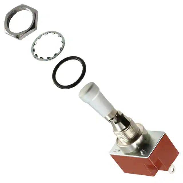


 工商网监
湘ICP备2023018690号
工商网监
湘ICP备2023018690号
