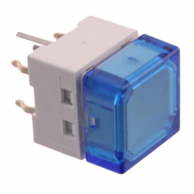
Sealed Tactile Switch
B3W
Through-hole-mounting Switches
That Are Mounting-compatible
with B3F Series.
Sealed Structure for High Reliability
• Sealed construction conforming to IP67 (IEC60529) provides high reliability in locations
exposed to dust or water. (* Excluding the terminal section.)
• Available in two sizes: 6 × 6 mm and 12 × 12 mm
sizes.
• Ground terminal available to protect against static
electricity.
• B32-series Key Tops mount to models with projected plungers.
RoHS Compliant
■
List of Models
6 × 6 mm Models
Type
B3W-1000
Series
Contact
material
Silver
plated
Plunger
Flat type
Height
4.3 mm
5.0 mm
Projected type
Note:
7.3 mm
Operating
force (OF)
Plunger
color
Bags
Without
ground
terminal
Minimum
packing
unit
With ground
terminal
1.57 N {160 gf}
max.
White
B3W-1000
B3W-1100
2.26 N {230 gf}
max.
Yellow
B3W-1002
B3W-1102
1.57 N {160 gf}
max.
White
B3W-1020
---
2.26 N {230 gf}
max.
Yellow
B3W-1022
1.57 N {160 gf}
max.
White
B3W-1050
B3W-1150
2.26 N {230 gf}
max.
Yellow
B3W-1052
B3W-1152
100 pcs
---
Minimum
packing
unit
100 pcs
Bulk Packaged, 100 switches per bag. Order in multiples of the package quantity.
12 × 12 mm Models
Type
B3W-4000
Series
Contact
material
Silver
plated
Plunger
Flat type
Projected type
Note:
Height
4.3 mm
7.3 mm
Operating
force (OF)
Plunger
color
Bags
Without
ground
terminal
Minimum
packing
unit
With ground
terminal
1.96 N {200 gf}
max.
White
B3W-4000
B3W-4100
3.43 N {350 gf}
max.
Yellow
B3W-4005
B3W-4105
1.96 N {200 gf}
max.
White
B3W-4050
3.43 N {350 gf}
max.
Yellow
B3W-4055
100 pcs
B3W-4150
Minimum
packing
unit
100 pcs
B3W-4155
Bulk Packaged, 100 switches per bag. Order in multiples of the package quantity.
1
�B3W
■
B3W
Ratings/Characteristics
Rating (resistive load)
1 to 50 mA, 3 to 24 VDC
Minimum applicable load (reference value) 10 μA at 1 VDC (resistive load)
Ambient operating temperature
-25°C to +70°C at 60%RH max. (with no icing or condensation)
Ambient operating humidity
35% to 85% (at +5 to +35°C)
Contact form
SPST-NO
Contact resistance (initial value)
100 mΩ max.
Insulation resistance
100 MΩ min. (at 250 VDC with insulation tester)
Dielectric strength
500 VAC, 50/60 Hz for 1 min
Bounce time
5 ms max.
Vibration resistance
Malfunction: 10 to 55 Hz, 1.5 mm double amplitude
Shock resistance
Destruction: 1,000 m/s2 {approx. 100 G} max.
Malfunction: 100 m/s2 {approx. 10 G} max.
Durability
B3W-1000:
1.57 N (standard force):1,000,000 operations min.
2.26 N (high-force):300,000 operations min.
B3W-4000:
1.96 N (standard force):3,000,000 operations min.
3.43 N (high-force):1,000,000 operations min.
Weight
6 × 6 mm: approx. 0.3 g, 12 × 12 mm: approx. 1 g
Degree of protection
IEC IP67
Washing
Possible
■
Operating Characteristics
6 × 6 mm Models
Type
B3W-1000 series
Operating force (OF)
Item
Model
1.57 N
2.26 N
B3W-1@@0
B3W-1@@2
Operating force (OF)
1.57 N {160 gf} max.
2.26 N {230 gf} max.
Releasing force (RF)
0.2 N {20 gf} min.
0.49 N {50 gf} min.
Pretravel (PT)
0.25+0.2/–0.1 mm
12 × 12 mm Models
Type
B3W-4000 series
Operating force (OF)
Item
Model
1.96 N
3.43 N
B3W-4@@0
B3W-4@@5
Operating force (OF)
1.96 N {200 gf} max.
3.43 N {350 gf} max.
Releasing force (RF)
0.29 N {30 gf} min.
0.49 N {50 gf} min.
Pretravel (PT)
■
0.3
+0.2
/–0.1 mm
Model Structure
Plunger
Spacer
Sealed rubber
Contact dome
Cover
Base
2
Fixed contact
�B3W
■
Dimensions
Note:
■
B3W
(Unit: mm)
The numbers used for terminals in the following graphics are indicated in the “Bottom View” diagram below. In this
diagram, the Switch is rotated so that the terminals are on the right and left-hand sides, and the OMRON logo appears
the right way up.
2
1
3
4
(Bottom View)
6 × 6 mm Models
Flat Plunger Type
(without Ground
Terminal)
6±0.2
6.6±0.2
B3W-1000
B3W-1002
Flat Plunger Type
(with Ground
Terminal)
3.3 dia.
B3W-1100
B3W-1102
4.5±0.2
6±0.2
3.3 dia.
6.6±0.2
4.5±0.2
1.5
4.3±0.2
4.3±0.2
3.4
3.4
3.5
3.5
(1.8)
0.3
0.7
6.5±0.5
0.7
0.7
6.5±0.5
PCB Processing Dimensions
(Reference Only) (Top View)
(PCB thickness, t=1.6)
Terminal Arrangement
/Internal Connections
(Top View)
4
0.7
0.25
7.7±0.5
7.7±0.5
PCB Processing Dimensions
(Reference Only) (Top View)
(PCB thickness, t=1.6)
(1.8)
0.3
0.7
Terminal Arrangement
/Internal Connections
(Top View)
4
3
3
4.5±0.1
4.5±0.1
2
2
4.1±0.1
1
Five, 1±0.05 dia.
Four, 1±0.05 dia.
6.5±0.1
1
5
6.5±0.1
Flat Plunger Type
(without Ground
Terminal)
6±0.2
3.3 dia.
6.6±0.2
4.5±0.2
ࠉ
B3W-1020
B3W-1022
5±0.2
3.4
3.5
(1.8)
0.3
0.7
0.7
6.5±0.5ࠉ
7.7±0.5ࠉ
PCB Processing Dimensions
(Reference Only) (Top View)
(PCB thickness, t=1.6)
Terminal Arrangement
/Internal Connections
(Top View)
4
3
2
1
4.5±0.1
6.5±0.1
Note:
Four, 1±0.05 dia.
Unless otherwise specified, a tolerance of ±0.4 mm applies to all dimensions. No terminal numbers are indicated on the Switches.
3
�B3W
B3W
Projected Plunger Type
(without Ground
Terminal)
B3W-1050
B3W-1052
6±0.2
Projected Plunger Type
(with Ground
Terminal)
3.3 dia.
B3W-1150
B3W-1152
4.5±0.2
6.6±0.2
1.8±0.1
2.4 × 2.4±0.1
6.6±0.2
1.8±0.1
7.3±0.2
6±0.2
3.3 dia.
4.5±0.2
2.4 × 2.4±0.1
7.3±0.2
4.3±0.2
4.3±0.2
3.4
3.5
3.4
3.5
(1.8)
0.3
0.7
6.5±0.5
(1.8)
0.3
0.7
1.5
0.7
7.7±0.5
0.7
0.7
0.25
6.5±0.5
7.7±0.5
PCB Processing Dimensions
(Reference Only) (Top View)
(PCB thickness, t=1.6)
Terminal Arrangement
/Internal Connections
(Top View)
4
PCB Processing Dimensions
(Reference Only) (Top View)
(PCB thickness, t=1.6)
3
4.5±0.1
4
3
2
1
4.5±0.1
2
6.5±0.1
Terminal Arrangement
/Internal Connections
(Top View)
1
4.1±0.1
Four, 1±0.05 dia.
Five, 1±0.05 dia.
6.5±0.1
Note:
4
Unless otherwise specified, a tolerance of ±0.4 mm applies to all dimensions. No terminal numbers are indicated on the Switches.
�B3W
■
B3W
12 × 12 mm Models
Flat Plunger Type
(without Ground
Terminal)
12±0.2
Flat Plunger Type
(with Ground
Terminal)
7.1 dia.
B3W-4000
B3W-4005
12±0.2
B3W-4100
B3W-4105
5±0.2
12±0.2
7.1 dia.
12±0.2
5±0.2
1.6
4.3±0.2
3.55
4.3±0.2
3.5
3.55
3.5
(1.8)
1.6 dia.
1
12.5±0.5
9
0.9
1
(1.8)
0.3
1.6
0.25
1
2.6
13.8±0.5
12.5±0.5
9
1
6.9
13.8±0.5
PCB Processing Dimensions
(Reference Only) (Top View)
(PCB thickness, t=1.6)
PCB Processing Dimensions
(Reference Only) (Top View)
(PCB thickness, t=1.6)
Terminal Arrangement
/Internal Connections
(Top View)
Two, 1.8±0.05 dia.
(for positioning boss)
4
3
2
1
Terminal Arrangement
/Internal Connections
(Top View)
Two, 1.8±0.05 dia.
(for positioning boss)
4
5±0.1
3
9±0.1
9±0.1
5±0.1
2
6.9±0.1
1
5
Five, 1.2±0.05 dia.
12.5±0.1
Four, 1.2±0.05 dia.
Projected Plunger Type
(without Ground
12
Terminal)
12.5±0.1
Projected Plunger Type
12
(with Ground
Terminal)
±0.2
B3W-4050
B3W-4055
12±0.2
B3W-4150
B3W-4155
5±0.2
1.8±0.1
12±0.2
@3.8±0.1
5±0.2
@3.8±0.1
1.8±0.1
7.3±0.2
4.3±0.2
±0.2
7.3±0.2
4.3±0.2
3.55
3.55
3.5
3.5
1.6 dia. 0.3
(1.8)
0.9
1
12.5±0.5
9
1
(1.8)
0.3
1.6
0.25
1
2.6
12.5±0.5
13.8±0.5
9
1
6.9
13.8±0.5
PCB Processing Dimensions
(Reference Only) (Top View)
(PCB thickness, t=1.6)
Two, 1.8±0.05 dia.
(for positioning boss)
5±0.1
Terminal Arrangement
/Internal Connections
(Top View)
4
3
2
1
PCB Processing Dimensions
(Reference Only) (Top View)
(PCB thickness, t=1.6)
Two, 1.8±0.05 dia.
(for positioning boss)
Terminal Arrangement
/Internal Connections
(Top View)
4
9±0.1
5±0.1
9±0.1
2
6.9±0.1
12.5±0.1
3
1
5
Four, 1.2±0.05 dia.
Five, 1.2±0.05 dia.
12.5±0.1
Note:
Unless otherwise specified, a tolerance of ±0.4 mm applies to all dimensions.
5
�B3W
■
B3W
Key Tops
B32-series Key Tops are available for projected plungers. Refer to the datasheet for the B32 for details.
■
Precautions
Be sure to read the safety precautions common to all Tactile Switches for correct use.
• Application examples provided in this document are for reference only. In actual applications, confirm equipment functions and safety before using the product.
• Consult your OMRON representative before using the product under conditions which are not described in the manual or applying the product to nuclear control systems, railroad
systems, aviation systems, vehicles, combustion systems, medical equipment, amusement machines, safety equipment, and other systems or equipment that may have a serious
influence on lives and property if used improperly. Make sure that the ratings and performance characteristics of the product provide a margin of safety for the system or
equipment, and be sure to provide the system or equipment with double safety mechanisms.
Note: Do not use this document to operate the Unit.
OMRON Corporation
Electronic and Mechanical Components Company
6
Contact: www.omron.com/ecb
Cat. No. A075-E1-07
1014(0207)(O)
�


 工商网监
湘ICP备2023018690号
工商网监
湘ICP备2023018690号
