General-purpose Basic Switch
Z
CSM_Z_DS_E_4_4
Best-selling Basic Switch Boasting
High Precision and Wide Variety
• A large switching capacity of 15 A with high repeat accuracy.
• A wide range of variations in contact form for your selection: basic,
split-contact, maintained-contact, and adjustable contact gap types.
• A series of standard models for micro loads is available.
• A series of molded terminal-type models incorporating safety
terminal protective cover is available.
Be sure to read Safety Precautions on page 26 and Safety Precautions
for All Basic Switches.
For the most recent information on models that have been certified for
safety standards, refer to your OMRON website.
Model Number Structure
Configuration
Basic models
Refer to page 3.
General-purpose
Drip-proof
Without terminal protective cover
Refer to page 5.
With terminal protective cover
Refer to page 5.
Molded terminal
Refer to page 2.
Split-contact models
General-purpose
Refer to page 4.
Maintained-contact models
General-purpose
Refer to page 4.
Basic Models
General-purpose
• A variety of actuators is available for a wide range of application.
• The contact mechanism of models for micro loads is a crossbar
type with gold-alloy contacts, which ensures highly reliable
operations for micro loads.
• Contact Gap:
H2: 0.20 mm (extra-high-sensitivity)
H: 0.25 mm (high-sensitivity, micro voltage current load)
G: 0.5 mm (standard)
E: 1.8 mm (high-capacity)
Drip-proof
• These Switches use a rubber boot on the actuator and adhesive fill
between the case and cover to increase resistance to drips.
• Models with drip-proof terminal protective covers and molded
terminals with resin filling are also available.
Split-contact Models
• This type is identical in construction to the general-purpose basic
switch except that it has two pairs of simultaneous acting contacts
by splitting moving contacts.
• Since the moving contacts are connected to a common terminal,
either parallel or series connection is possible.
• Highly reliable micro load switching is ensured if the model is used
as a twin-contact switch.
Maintained-contact Models
• The maintained-contact type has a reset button at the bottom of the
switch case, in addition to the pushbutton (plunger) located on the
opposite side of the reset button. Use these buttons alternately.
• Since the Switch has greater pretravel than overtravel, it is suitable
for use in reversible control circuits, manual reset circuits, safety
limit circuits, and other circuits which are not preferable for
automatic resetting. (For further details, refer to individual
datasheets.)
1
�Z
Model Number Legend
Basic Models
Standard Models (Drip-proof Type/Molded Terminals)
Z-@@@@-@
Z-@55-M@@ @M
(1)(2)(3)(4) (5)
(1) Ratings
01
15
: 0.1 A (micro load)
: 15 A
(2) Contact Gap
H2
H
G
E
: 0.20 (extra-high-sensitivity)
: 0.25 mm (high-sensitivity,
micro load)
: 0.5 mm (standard)
: 1.8 mm (high-capacity)
(3) Actuator
None
S
D
K
K3
Q3
Q
:
:
:
:
:
:
:
Q8
Q22
Q21
:
:
:
L
L2
W21
W
W3
W32
W4
W44
W78
:
:
:
:
:
:
:
:
:
W52
:
W22
W2
W25
W49
W54
W2277
:
:
:
:
:
:
M
M22
:
:
M2
NJ
NJS
:
:
:
Pin plunger
Slim spring plunger
Short spring plunger
Spring plunger (medium OP)
Spring plunger (high OP)
Panel mount plunger (low OP)
Panel mount plunger (medium
OP)
Panel mount plunger (high OP)
Panel mount roller plunger
Panel mount cross roller
plunger
Leaf spring (high OF)
Roller leaf spring
Short hinge lever
Hinge lever (low OF)
Hinge lever (medium OF)
Hinge lever (high OF)
Low-force hinge lever
Long hinge lever
Low-force wire hinge lever
(low OF)
Low-force wire hinge lever
(high OF)
Short hinge roller lever
Hinge roller lever
Hinge roller lever (large roller)
Short hinge cross roller lever
Hinge cross roller lever
Unidirectional short hinge
roller lever (low OF)
Reverse hinge lever
Reverse short hinge roller
lever
Reverse hinge roller lever
Flexible rod (high OF)
Flexible rod (low OF)
(1)
(2)(3) (4)
(1) Drip-proof Type
(2) Lead Outlets
None
19
: VSF
: VCT
(3) Directions of Lead
Outlets (See following L Type
diagrams.)
L
R
D
D Type
R Type
: Left
: Right
: Descending
(4) Length of Lead
Outlets
1
3
: 1m
: 3m
Split-contact Models
Maintained-contact Models
Z-10F@Y-B
Z-15-E@R
(1) (2)(3)(4) (5)
(1) (2)(3)(4)
(1) Ratings
10
: 10 A (split-contact models)
(2) Contact Gap
F
: 1 mm (high-capacity)
(3) Actuator
None
S
D
Q
Q22
W
W22
W2
M22
:
:
:
:
:
:
:
:
:
Pin plunger
Slim spring plunger
Short spring plunger
Panel mount plunger
Panel mount roller plunger
Hinge lever
Short hinge roller lever
Hinge roller lever
Reverse short hinge roller
lever
(1) Ratings
15
: 15 A
(2) Contact Gap
E
: 1.8 mm (high capacity)
(3) Actuator
None
S
W
: Pin plunger
: Slim spring plunger
: Hinge lever
(4) Structure
R
: Maintained-contact models
(4) Construction
Y
: Split-contact models
(5) Terminals
B
: Screw terminal
(with toothed washer)
(4) Degree of Protection
None
55
A55
: General-purpose
: Drip-proof
(not include the terminals)
: Drip-proof
(including the terminals)
(5) Terminals
None
B
B5V
: Solder terminal
: Screw terminal
(with toothed washer)
: Screw terminal with terminal
cover (for Z-15G@A55 only)
Note: For combinations of models, Ordering
Information on page 3 to 6.
2
�Z
Ordering Information
Main Unit
Basic Models (General-purpose)
Classification
Actuator
Contact gap
Terminal *1
Pin plunger
Slim spring plunger
Short spring
plunger
Panel mount
plunger
Standard
High-sensitivity
G (0.5 mm)
Model
H (0.25 mm)
Model
Z-15H2
Z-15E
Z-01H
Z-15H2-B
Z-15E-B
Z-01H-B
---
---
Z-15GS
Z-15HS
Z-15GS-B
Z-15HS-B
Z-15GD
Z-15HD
Z-15GD-B
Z-15HD-B
Z-15GQ3
Z-15GQ
Z-15HQ
Z-15GQ-B
Z-15HQ-B
High
OP
Z-15GQ8-B
Z-15GQ8
Z-15HQ22
Z-15HQ22-B
Panel mount cross
roller plunger
Z-15GQ21
Z-15HQ21
Z-15GQ21-B
Z-15HQ21-B
Z-15GL
Z-15GL2
Z-15GL2-B
Z-15GW21
Z-15GW21-B
Lowforce wire
hinge
lever
Z-01HQ
Z-01HQ-B
---
---
Z-15EQ22
Z-15EQ22-B
Z-15EQ21
Z-15EQ21-B
-----
---
---
---
---
---
---
---
---
---
---
---
---
---
---
---
Z-15HW
Medium
OP
Z-15GW3-B
High
OP
Z-15GW32-B
Z-15GW3
---
Z-15GW4
Z-15HW24
Z-15GW4-B
Z-15HW24-B
Z-15HW78
---
Z-15HW78-B
Z-15HW52
Z-15HW52-B
Z-15HW22
Z-15GW22-B
Z-15HW22-B
Short hinge cross
roller lever
Z-15GW49-B
Reverse hinge lever *2
Z-15EQ
Z-15EQ-B
---
Z-15GW22
Unidirectional
short hinge
roller lever
---
---
Z-15HW-B
Z-15GW49
---
Standard
Z-15GW2
Z-15HW2
Z-15GW2-B
Z-15HW2-B
Large
roller
Z-15GW25-B
Z-15GW25
Z-15GW54
Hinge cross roller
lever
---
---
Short hinge roller
lever
Hinge roller
lever
Z-01HD
Z-01HD-B
---
Z-15GW
High
OP
---
Z-15ED
Z-15ED-B
---
Z-15GW-B
Low
OP
---
Z-01HS
Z-01HS-B
---
Low
OP
Z-15GW32
---
---
Z-15GQ22
Z-15GL-B
---
---
Z-15GQ22-B
Low-force hinge
lever
H (0.25 mm)
Model
Z-15H
Panel mount roller
plunger
Hinge lever
E (1.8 mm)
Model
Z-15H-B
Medium
OP
Short hinge lever
Micro load
Z-15G
Z-15GQ3-B
Roller leaf spring
High-capacity
Z-15G-B
Low
OP
Leaf spring
Extra-high
sensitivity
H2 (0.20 mm)
Model
Z-15GW54-B
-----
Z-15EW22
Z-01HW22
Z-15EW22-B
Z-01HW22-B
---
---
---
---
---
---
---
-----
---
---
---
---
---
---
---
---
---
---
---
---
---
---
---
---
---
---
---
Z-15GW2277
Parallel
Z-15GW2277-B
Z-15GM
Z-15GM-B
Z-15GM22
Reverse short
hinge roller lever *2
Z-15GM22-B
Reverse hinge
roller lever *2
Z-15GM2-B
Z-15GM2
*1.
: Solder terminal
: Screw terminal
*2. The pin plungers of reverse-type models are continuously pressed by the actuator levers with compression coil springs and the pin plungers are freed by operating
the levers. Reverse-type models are highly vibration- and shock-resistive because the pin plungers are normally pressed.
3
�Z
Minimum Order Lot
The following models are available at the minimum order lot specified below.
Orders must be placed per lot.
Classification
Actuator
Short spring plunger
Standard
High-sensitivity
Z-15GD-B
---
Panel mount plunger
Z-15GQ
Z-15GQ-B
Z-15GQ8-B
---
Panel mount roller plunger
Z-15GQ22
Z-15GQ22-B
---
Z-15GQ21-B
---
Z-15GW21-B
---
Z-15GW
Z-15GW-B
---
Z-15GW4-B
Z-15HW24-B
---
Z-15HW78-B
Short hinge roller lever
Z-15GW22
Z-15GW22-B
---
Hinge roller lever
Z-15GW2
Z-15GW2-B
---
Z-15GM22-B
---
Z-15GM2-B
---
Panel mount cross roller
plunger
Short hinge lever
Hinge lever
Low-force hinge lever
Low-force hinge wire lever
Reverse short hinge roller
lever
Reverse hinge roller lever
Split-contact Models
Actuator
Pin plunger
Slim spring plunger
Short spring plunger
Minimum
order lot (pcs)
10
Maintained-contact Models
Contact gap
Terminal *1
F (1.0 mm)
Model
--Z-10FY-B
Actuator
Pin plunger
Model
Z-15ER
Slim spring plunger
Z-15ESR
Hinge lever
Z-15EWR
--Z-10FSY-B
--Z-10FDY-B
--Panel mount plunger
Panel mount roller
plunger
Hinge lever
Short hinge roller
lever
Z-10FQY-B
--Z-10FQ22Y-B
--Z-10FWY-B
--Z-10FW22Y-B
--Hinge roller lever
Reverse short hinge
roller lever *2
Z-10FW2Y-B
--Z-10FM22Y-B
*1.
: Solder terminal
: Screw terminal
*2. The pin plungers of reverse-type models are continuously pressed by the
actuator levers with compression coil springs and the pin plungers are freed
by operating the levers. Reverse-type models are highly vibration- and
shock-resistive because the pin plungers are normally pressed.
4
�Z
Basic Models (Drip-proof Models
Standard, Microload )
Classification
Contact gap
Drip-proof terminal
protective cover
Actuator
Terminal *1
Pin plunger
Panel mount plunger
Micro load
H (0.25 mm)
Not provided
Provided
Model
Model
Model
---
Z-01H55
Z-15G55-B
Z-15GA55-B5V
Z-01H55-B
Z-15GK55
Low
OP
Z-15GK55-B
High
OP
Z-15GK355
---
Z-15GK355-B
Z-15GK3A55-B5V
Z-15GQ55
---
Z-15GQ55-B
Z-15GQA55-B5V
Z-15GQ2255
--Z-15GQ22A55-B5V
Panel mount cross
roller plunger
---
---
Z-15GQ2155-B
Z-15GQ21A55-B5V
Short hinge lever
Long hinge lever
Hinge lever
Short hinge roller lever
Z-15GL55
Z-15GL55-B
Z-15GL255
Z-15GL255-B
Z-15GW2155
Z-15GW2155-B
Reverse hinge lever *2
-----------
---
---
---
---
---
---
Z-15GW4455
---
Z-15GW4455-B
Z-15GW44A55-B5V
Z-15GW55
---
Z-15GW55-B
Z-15GWA55-B5V
-----
Z-15GW2255
---
Z-01HW2255
Z-15GW2255-B
Z-15GW22A55-B5V
Z-01HW2255-B
Z-15GW255
---
Z-15GW255-B
Z-15GW2A55-B5V
Hinge roller lever
Unidirectional short
hinge roller lever
Z-01HD55-B
---
Z-15GQ2255-B
Roller leaf spring
Z-01HD55
---
Z-15GD55-B
Panel mount roller
plunger
Leaf spring
Not provided
Z-15G55
Z-15GD55
Short spring plunger
Spring plunger
Standard
G (0.5 mm)
Z-15GW227755
---
Z-15GW227755-B
Z-15GW2277A55-B5V
Z-15GM55
Z-15GM55-B
Z-15GM2255
Reverse short hinge
roller lever *2
Z-15GM2255-B
Reverse hinge roller
lever *2
Z-15GM255-B
Z-15GM255
---
---
---
---
---
---
---
---
---
---
Z-15GNJ55
Flexible rod (coil spring) *3
Z-15GNJ55-B
*1.
: Solder terminal
: Screw terminal
*2. The pin plungers of reverse-type models are continuously pressed by the actuator levers with compression coil springs and the pin plungers are freed by operating
the levers.
*3. The tip is made of resin.
Minimum Order Lot
The following models are available at the minimum order lot specified
below.
Orders must be placed per lot.
Classification
Actuator
Contact gap
Standard
G (0.5 mm)
Short spring plunger
Z-15GD55-B
Spring plunger
Z-15GK55-B
Minimum order
lot (pcs)
Z-15GW4455-B
Hinge lever
Z-15GW55
Z-15GW55-B
Short hinge roller lever
10
Z-15GW2255
Z-15GW2255-B
Hinge roller lever
Z-15GW255-B
Flexible rod (coil spring)
Z-15GNJ55-B
5
�Z
Basic Models (Drip-proof Models High-sensitivity )
Classification
Contact gap
Drip-proof terminal protective cover
Actuator
Terminal *
The following models are available at the minimum order lot specified
below.
Orders must be placed per lot.
Classification High-sensitivity Minimum order
lot (pcs)
Actuator
Contact gap
H (0.25 mm)
High-sensitivity
H (0.25 mm)
Not provided
Model
Z-15HNJS55
Flexible rod
(steel wire)
*
Minimum Order Lot
Flexible rod (steel wire)
Z-15HNJS55-B
10
Z-15HNJS55-B
: Solder terminal
: Screw terminal
Specifications
Ratings (Basic, Split-contact and Maintained contact Models)
Z-15 (Except Micro Load and Flexible Rod Models)
Item
Contact
gap
G, H,
H2, E
G
H, H2
E
Non-inductive load (A)
Resistive load
Lamp load
Rated
voltage
125 VAC
250 VAC
500 VAC *
8 VDC
14 VDC
30 VDC
125 VDC
250 VDC
8 VDC
14 VDC
30 VDC
125 VDC
250 VDC
8 VDC
14 VDC
30 VDC
125 VDC
250 VDC
NC
NO
15 (10) *
15 (10) *
10
15
15
6
0.5
0.25
15
15
2
0.4
0.2
15
15
15
0.75
0.3
NC
NO
3
2.5
1.5
3
3
3
0.5
0.25
3
3
2
0.4
0.2
3
3
3
0.75
0.3
1.5
1.25
0.75
1.5
1.5
1.5
0.5
0.25
1.5
1.5
1.4
0.4
0.2
1.5
1.5
1.5
0.75
0.3
Z-01H
Inductive load (A)
Inductive load
Motor load
NC
NO
15 (10) *
15 (10) *
6
15
10
5
0.05
0.03
15
10
1
0.03
0.02
15
15
10
0.4
0.2
NC
NO
5
3
1.5
5
5
5
0.05
0.03
5
5
1
0.03
0.02
5
5
5
0.4
0.2
2.5
1.5
0.75
2.5
2.5
2.5
0.05
0.03
2.5
2.5
1
0.03
0.02
2.5
2.5
2.5
0.4
0.2
* Figures in parentheses are for the Z-15HW52, Z-15HW78(-B) and Z-15H2(-B) models, the AC ratings of
these models are 125 and 250 V only.
Rated voltage
125 VAC
8 VDC
14 VDC
30 VDC
Resistive load (A)
NC
NO
0.1
0.1
0.1
0.1
Note: 1. The above current ratings are the values
of the steady-state current.
2. Inductive load has a power factor of 0.4
min. (AC) and a time constant of 7 ms
max. (DC).
3. Lamp load has an inrush current of 10
times the steady-state current.
4. Motor load has an inrush current of 6
times the steady-state current.
5. The normally closed and normally open
ratings of reverse hinge lever models are
opposite to each other.
6. The AC ratings of molded terminals are
125 and 250 V only.
7. The ratings values apply under the
following test conditions:
(1) Ambient temperature: 20±2°C
(2) Ambient humidity: 65±5%RH
(3) Operating frequency: 20 operations/min
Z-15 (Flexible Rod Models)
125 VAC
250 VAC
8 VDC
14 VDC
30 VDC
125 VDC
250 VDC
Non-inductive load (A)
Resistive load
Lamp load
NC
NO
NC
NO
15
2
1
15
1
0.5
15
2
1
15
2
1
2
2
1
0.4
0.4
0.4
0.2
0.2
0.2
Inductive load (A)
Inductive load
Motor load
NC
NO
NC
NO
7
2.5
2
5
1.5
1
7
3
1.5
7
3
1.5
1
1
0.5
0.03
0.03
0.03
0.02
0.02
0.02
Use the switch within the operating
range.
Voltage (V)
Rated voltage
5 mW
800 mW
0.16 mA
30
26 mA
24
Micro load area
Z-01H
Standard
load area
Z-15H, H2
Z-15G
Z-15E
Z-10FY
Z-15ER
Z-10F
Item
Contact
gap
Series
connection
Parallel
connection
Rated
voltage
125 VAC
250 VAC
30 VDC
125 VDC
250 VDC
125 VAC
250 VAC
30 VDC
125 VDC
250 VDC
Non-inductive load (A)
Resistive load
Lamp load
NC
NO
10
10
10
1
0.6
6
6
6
0.6
0.3
NC
4
2.5
4
1
0.6
3
2.5
4
0.6
0.3
NO
2
1.5
2
1
0.6
1.5
1.25
2
0.6
0.3
Inductive load (A)
Inductive load
Motor load
NC
NO
6
6
6
0.1
0.05
4
4
4
0.1
0.05
NC
5
3
6
0.1
0.05
4
2
6
0.1
0.05
NO
2.5
1.5
3
0.1
0.05
2
1
3
0.1
0.05
12
Unusable
range
5
0
0.1
100 mA 160 mA
1 mA
1
10
100
1,000
Current (mA)
Minimum
applicable
load
Z-01H
Z-15@, Z-10FY
5 VDC 1 mA
5 VDC 160 mA
6
�Z
Certified Standard Ratings
Ask your OMRON representative for information on certified models.
TÜV (EN61058-1)
UL/CSA (General ratings only)
Rated
Model
voltage
125 VAC
250 VAC
480 VAC
30 VDC
125 VDC
250 VDC
Z-15
Z-10F
Z-01H
15A 1/8HP
15A 1/4HP
15A
--0.5A
0.25A
6A 1/10HP
6A 1/8HP
6A
--0.6A
0.3A
0.1A
----0.1A
-----
Rated
Model
voltage
250 VAC
125 VAC
30 VDC
Z-15H@
Z-15G@
Z-01H@
15 A
-----
15 A
-----
--0.1 A
0.1 A
Z-15H@
Z-15G@
Z-01H@
15 A
-----
15 A
-----
--0.1 A
0.1 A
CCC (GB14048.5)
Rated
Model
voltage
250 VAC
125 VAC
30 VDC
Characteristics
Classification
Operating speed
Mechanical
Operating
frequency
Electrical
Insulation resistance
Contact resistance
Z-15 (except micro
Z-01H
Z-15 (flexible rod)
Z-10F
Z-15H2
load and flexible rod)
0.01 mm to 1 m/s *1
1 mm to 1 m/s
0.1 mm to 1 m/s *1
0.01 mm to 1 m/s
240 operations/min
120 operations/min
240 operations/min
240 operations/min
20 operations/min
100 MΩ min. (at 500 VDC)
15 mΩ max. (initial value) 50 mΩ max. (initial value) 15 mΩ max. (initial value)
25 mΩ max. (initial value) 15 mΩ max. (initial value)
Between contacts of same polarity
Between contacts of same polarity
Between contacts of
Between contacts of same
Contact gap G: 1,000 VAC, 50/60 Hz for 1 min
Contact gap G: 1,000 VAC, 50/60 Hz for 1
same polarity
polarity
Contact gap H: 600 VAC, 50/60 Hz for 1 min
min
600VAC, 50/60Hz for
Contact gap F: 1,500 VAC,
Dielectric strength
Contact gap E: 1,500 VAC, 50/60 Hz for 1 min
Contact gap H: 600 VAC, 50/60 Hz for 1 min 50/60 Hz for 1 min
1min
Between current-carrying metal parts and ground, and between each terminal and non-current-carrying metal parts 2,000 VAC, 50/60 Hz for 1 min
10 to 20 Hz, 1.5-mm double
Vibration
10 to 55 Hz, 1.5-mm double amplitude *5
Malfunction 10 to 55 Hz, 1.5-mm double amplitude *5
amplitude *5
resistance
2
Destruction 1,000 m/s max.
Shock
resistance
Malfunction 300 m/s2 max. *2 *5
50 m/s2 max. *5
300 m/s2 max. *3 *5
100 m/s2 max.
500,000 operations
20,000,000 operations
Contact gap G, H: 20,000,000 operations min.
1,000,000 operations min.
Mechanical
min. *1
min.
Contact gap E: 300,000 operations
Durability
Contact gap G, H: 500,000 operations min.
100,000 operations
500,000 operations
Electrical
100,000 operations min.
Contact gap E: 100,000 operations min.
min.
min.
General-purpose IP00
Degree of
protection
Drip-proof Equivalent to IP62 (except terminals)
Degree of protection
Class I
against electric shock
Proof tracking index
175
(PTI)
Ambient operat- General-purpose −25°C to 80°C (with no icing)
ing temperature Drip-proof −15°C to 80°C (with no icing)
Ambient operat- General-purpose 35% to 85%RH
ing humidity
Drip-proof 35% to 95%RH
Weight
Approx. 22 to 58 g
Approx. 42 to 48 g
Approx. 34 to 61 g
Approx. 22 g
Item
*1.
*2.
*3.
*4.
*5.
The values are for the plunger models. (For the lever models, the values are at the plunger section.) (Consult your OMRON representative for other models.)
The values are for the Z-15G pin plunger.
The values are for the Z-10FY-B.
The values are for the pin plunger. The durability for models other than the pin plunger is 10,000,000 min.
Malfunction: 1 ms max.
Contacts Specification
Item
Classification
Contacts
Inrush current
Z-15
Z-01H
Shape
Rivet
Single crossbar
Z-10F
Rivet
Material
Silver
Gold alloy
Silver
NC
30 A max.
0.1 A max.
40 A max.
NO
15 A max.
0.1 A max.
20 A max.
Engineering Data
10,000
Ambient temperature: 20±2°C
Ambient humidity: 65±5%RH
Without load
Operating frequency: 240 operations/min
5,000
3,000
1,000
Electrical Durability (Z-15G)
Durability (x104 operations)
Durability (x104 operations)
Mechanical Durability (Z-15G)
5,000
Ambient temperature: 20±2°C
Ambient humidity: 65±5%RH
Operating frequency: 20 operations/min.
3,000
125 VAC cos dia. = 1
125 VAC cos dia. = 0.4
1,000
500
250 VAC cos dia. = 1
250 VAC
cos dia. = 0.4
300
500
100
300
50
500 VAC cos dia. = 1
30
100
500 VAC cos dia. = 0.4
10
0
0.1
0.2
0.3
0.4
0.5
0.6 0.7 0.8
Overtravel (mm)
0
2
4
6
8
10 12 14 16
Switching Current (A)
7
�Z
Structure
Split-contact Models
Basic Models
Contact Form
Contact Form (SPDT)
COM
NC
NC
NO
COM
NO
Note: The Z-15GM is a reversible model and the NO and NC positions are
reversed.
NC
NO
Note: The NO and NC terminal arrangement is reversed for Models with
reverse operation (Z-10FM).
Molded Terminals
COM (Black)
(Red) NC
Connection Example
(White) NO
( ) indicates wire color.
Series Connection
Parallel Connection
Note: The Z-15GM is a reversible model and the NO and NC positions are
reversed.
Structure
Drip-proof Construction
• Without Terminal Protective Cover
Rubber boot
Fixed contact (b)
Movable spring
Glued surface
(adhesive is
filled between
case and cover)
Movable contact
Spring pivot
Fixed contact (a)
Maintained-contact Models
Contact Form
COM
NC
NO
• With Terminal Protective Cover
Rubber boot (weather-resistive
chloroprene is used)
Pushbutton for resetting
Stainless-steel stopper
(improves sealing)
Rubber packing (improves
sealing between switch
housing and terminal cover)
Terminal protective covers are sold separately
for maintenance purposes, which can be,
however, used with the Z-@-B5V models only.
For details, refer to page 22.
8
�Z
Dimensions
(Unit: mm)
Mounting
Use M4 screws with plane washers and spring washers to mount the
Switch. Tighten each mounting screw securely to a torque of 1.18 to
1.47 N·m.
When mounting the Switch to a panel, use a tightening torque of 2.94
to 4.9 N·m for the hexagonal nuts on the actuator.
Panel Mount Plunger
Two, 4.2 dia. mounting holes or M4
Panel Mount Roller Plunger
12.5+0.2
0 dia.
12.5 +0.2
0 dia.
5 +0.2
0
25.4 ±0.1
13 +0.2
0
Basic Models
General-purpose
and Split-contact Models
Terminals
Basic Models
Screw Terminals (-B)
Split-contact Models
Solder Terminal (-A) (“-A” is not included
in the model numbers.)
Screw Terminals (Y-B)
5.6
6.4
9.2
11.9
25.4 ±0.1
20
17.45 ±0.2
23
17.45 ±0.2
3
2
49.2
Three, M4 × 5.5
Terminal screws
(with toothed
washer)
3
2
NO
COM
NC
NC
1
17.45±0.2
1
NC
NC
NO
NO
COM
COM
17.1
NO
20
11.9
Five, M3.5 × 5.5
terminal screws
(with toothed
washer)
Appropriate terminal screw tightening torque: 0.49
to 0.78 N·m.
Note: With reverse action models (Z-10FM), the
positions of NO and NC terminals are
reversed.
49.2
Appropriate terminal screw tightening torque: 0.78
to 1.18 N·m.
Note: With reverse action models (Z-15GM), the positions of NO and NC terminals are reversed.
Dimensions and Operating Characteristics
The models, illustrations, and graphics are for screw-terminal models (-B). The “-A” at the end of the model number for solder terminal models has been omitted. For
details of the terminals, see above.
Pin Plunger
Z-15G-B
Z-15E-B
Z-15H2-B
Z-01H-B
Z-15H-B
Z-10FY-B
2.3 dia.
PT
23.3 ±0.25
4.2 +0.075
-0.025 dia. hole
2.3SR *
OP
24.2
9.2
4.2 +0.075
-0.025
4.36 +0.1
-0.05 dia.
25.4 ±0.1
17.45±0.2
* Stainless-steel plunger
11.9
49.2
Operating
Characteristics
Operating force
Release force
Pretravel
Overtravel
Movement Differential
RF
PT
OT
MD
Model
Z-15G-B
Z-15H2-B
Z-15H-B
Z-15E-B
Z-01H-B
Z-10FY-B
OF
min.
max.
min.
max.
2.45 to 3.43 N
1.12 N
0.4 mm
0.13 mm
0.05 mm
1.96 to 2.5 N
1.12 N
0.3 mm
0.13 mm
0.005 to 0.008 mm
1.96 to 2.75 N
1.12 N
0.3 mm
0.13 mm
0.025 mm
6.12 to 7.85 N
1.12 N
0.8 mm
0.13 mm
0.13 mm
2.45 N max.
0.78 N
0.5 mm
0.13 mm
0.04 mm
4.46 to 7.26 N
1.12 N
0.8 mm
0.13 mm
0.1 mm
Operating Position OP
Slim Spring Plunger
Z-15GS-B
Z-01HS-B
Z-15HS-B
Z-10FSY-B
15.9±0.4 mm
5.2 dia.
PT
4 dia.
23.3 ±0.25
*
4.2 +0.075
-0.025 dia. hole
OP
9 dia.
24.2
9.2
4.2 +0.075
-0.025
4.36 +0.1
-0.05 dia.
25.4 ±0.1
17.45 ±0.2
11.9
* Stainless-steel plunger (flat, 1R chamfered)
49.2
OF
RF
PT
OT
MD
OP
min.
max.
min.
max.
Z-15GS-B
Z-15HS-B
Z-01HS
Z-10FSY-B
2.45 to 3.43 N
1.12 N
0.4 mm
1.6 mm
0.05 mm
1.96 to 2.79 N
1.12 N
0.3 mm
1.6 mm
0.025 mm
2.45 N max.
0.78 N
0.5 mm
1.6 mm
0.05 mm
4.46 to 7.26 N
1.12 N
0.8 mm
1.6 mm
0.1 mm
28.2±0.5 mm
Note: Unless otherwise specified, a tolerance of ±0.4 mm applies to all dimensions.
9
�Z
Short Spring Plunger
Z-15GD-B
Z-01HD-B
Z-15HD-B
Z-10FDY-B
Z-15ED-B
12.3 dia.
10 dia.
23.3 ±0.25
12SR *
PT
7.15 dia.
4.2 +0.075
-0.025 dia. hole
OP
24.2
9.2
4.2 +0.075
-0.025
4.36 +0.1
-0.05 dia.
17.45 ±0.2
* Plated iron plunger
11.9
25.4 ±0.1
49.2
OF
RF
PT
OT
MD
min.
max.
min.
max.
Z-15GD-B
Z-15HD-B
Z-15ED-B
Z-01HD-B
Z-10FDY-B
2.45 to 3.43 N
1.12 N
0.4 mm
1.6 mm
0.05 mm
1.96 to 2.79 N
1.12 N
0.3 mm
1.6 mm
0.025 mm
6.13 to 7.85 N
1.12 N
0.8 mm
1.6 mm
0.13 mm
2.45 N max.
0.78 N
0.5 mm
1.6 mm
0.05 mm
4.46 to 7.26 N
1.12 N
0.8 mm
1.6 mm
0.1 mm
OP
Panel Mount Plunger
Z-15GQ-B
Z-01HQ-B
Z-15HQ-B
Z-10FQY-B
Z-15EQ-B
Z-15GQ3-B *
Z-15GQ8-B *
21.5±0.5 mm
8.35 dia.
23.3 ±0.25
11.9SR
*1
PT
OP
13.1
16.3
*4
16 dia.
4.2 +0.075
-0.025
4.36+0.1
-0.05 dia.
* The external
dimensions of the
actuator vary.
OF
RF
PT
OT
MD
min.
max.
min.
max.
25.4 ±0.1
49.2
Z-15GQ-B
Z-15HQ-B
Z-15EQ-B
Z-01HQ-B
Z-10FQY-B
Z-15GQ3-B
Z-15GQ8-B
2.45 to 3.43 N
1.12 N
0.4 mm
5.5 mm
0.05 mm
1.96 to 2.79 N
1.12 N
0.3 mm
5.5 mm
0.025 mm
6.13 to 7.85 N
1.12 N
0.8 mm
5.5 mm
0.13 mm
2.45 N max.
0.78 N
0.5 mm
5.5 mm
0.05 mm
4.46 to 7.26 N
1.12 N
0.8 mm
5.5 mm
0.1 mm
2.45 to 3.43 N
1.12 N
4.2 mm
2.5 mm
2.2 mm
2.45 to 3.43 N
1.12 N
0.5 mm
5.5 mm
0.05 mm
18.8±0.8 mm
32.5±1 mm
OP
Panel Mount Roller Plunger
Z-15GQ22-B Z-15EQ22-B
Z-15HQ22-B Z-10FQ22Y-B
Note: 1. Do not use the M12 mounting screw
and the case mounting hole at the
same time, or excessive pulling force
*2
will be imposed on the switch and the
case and cover may be damaged.
4.2 +0.075
-0.025 dia. hole
*3
2. On the model Z-15GQ3-B, PT can be
set to a value larger than that for the Z15GQ.
3. On the model Z-15GQ8-B, operating
9.2
position can be adjusted by providing a
screw in the plunger section.
4. On the model Z-15GQ8-B, the M3 hole
17.45±0.2
11.9
*1. Stainless-steel plunger
with a depth of 10 mm is a through
*2. Two hexagonal nuts (2 t × 14 width across flats)
hole. Take precautions so that no
*3. Two lock nuts (2 t × 15.6 width across flats)
*4. Incomplete screw part with a maximum length
water or screw lock agent penetrates
of 1.5 mm.
into the hole.
M12 × 1
mounting screw
21.8±0.8 mm
12.7 dia. × 4.8 *1
23.3 ±0.25
PT
*2
OP
15.5
16.3
4.2 +0.075
-0.025
*3
M12 × 1
mounting
screw
dia. hole
16 dia.
Note: Do not use the M12 mounting screw and
the case mounting hole at the same time,
or the case may be damaged.
9.2
4.2 +0.075
-0.025
4.36 +0.1
-0.05 dia.
25.4 ±0.1
17.45±0.2
11.9
*1. Stainless-steel roller
*2. Two hexagonal nuts (3 t × 17 width across flats)
*3. Incomplete screw part with a maximum length of 1.5 mm.
49.2
OF
RF
PT
OT
MD
OP
min.
max.
min.
max.
Z-15GQ22-B
Z-15HQ22-B
Z-15EQ22-B
Z-10FQ22Y-B
2.45 to 3.43 N
1.12 N
0.4 mm
3.58 mm
0.05 mm
1.96 to 2.79 N
1.12 N
0.3 mm
3.58 mm
0.025 mm
6.13 to 7.85 N
1.12 N
0.8 mm
3.58 mm
0.13 mm
4.46 to 7.26 N
1.12 N
1 mm
3.55 mm
0.1 mm
33.4±1.2 mm
Note: Unless otherwise specified, a tolerance of ±0.4 mm applies to all dimensions.
10
�Z
Panel Mount Cross Roller Plunger
Z-15GQ21-B Z-15EQ21-B
PT
Z-15HQ21-B
23.3 ±0.25
12.7 dia. × 4.8 *1
OF
RF
PT
OT
MD
*2
OP
15.5
16.3
M12 × 1
mounting
screw
4.2 +0.075
-0.025 dia. hole
*3
16 dia.
min.
max.
min.
max.
Z-15HQ21-B
1.96 to 2.79 N
1.12 N
0.3 mm
3.58 mm
0.025 mm
OP
33.4±1.2 mm
9.2
Z-15EQ21-B
4.2 +0.075
-0.025
OF
RF
PT
OT
MD
4.36 +0.1
-0.05 dia.
17.45±0.2
11.9
25.4 ±0.1
*1. Stainless-steel roller
*2. Two hexagonal nuts (3 t × 17 width
across flats)
*3. Incomplete screw part with a maximum
length of 1.5 mm.
49.2
Note: Do not use the M12 mounting screw and the
case mounting hole at the same time, or the
case may be damaged.
Leaf Spring
Z-15GL-B
Z-15GQ21-B
2.45 to 3.43 N
1.12 N
0.4 mm
3.58 mm
0.05 mm
min.
max.
min.
max.
OP
6.13 to 7.85 N
1.12 N
0.8 mm
3.58 mm
0.13 mm
33.4±1.2 mm
t = 0.3*
4.8
49.6 ±0.8
4.2+0.075
-0.025 dia. hole
FP
OP
23.9
9.2
4.2 +0.075
-0.025
4.36 +0.1
-0.05 dia.
* Stainless-steel spring lever
49.2
Roller Leaf Spring
Z-15GL2-B
1.38 N
0.14 N
1.6 mm
1.3 mm
FP max.
OP
20.6 mm
17.4±0.8 mm
* When operating, be sure not
to exceed 1.6 mm.
17.45±0.2
11.9
25.4 ±0.1
OF max.
RF min.
OT *min.
MD max.
9.5 dia. × 4
(plastic toller)
46 ±0.8
t = 0.3 *
4.2 +0.075
-0.025 dia. hole
FP
OP
23.9
9.2
4.2+0.075
-0.025
4.36 +0.1
-0.05 dia.
25.4 ±0.1
17.45 ±0.2
* Stainless-steel spring lever
11.9
26.2
1.38 N
0.14 N
1.6 mm
1.3 mm
FP max.
OP
31.8 mm
28.6±0.8 mm
* When operating, be sure not
to exceed 1.6 mm.
49.2
Short Hinge Lever
Z-15GW21-B
OF max.
RF min.
OT *min.
MD max.
t=1*
4.9
.2R
28
20.2 16.9
13.9
FP
OP
OF
RF
OT
MD
9.2
4.2 +0.075
-0.025
4.2 +0.075
-0.025 dia. hole
4.36 +0.1
-0.05 dia.
25.4 ±0.1
FP max.
OP
17.45 ±0.2
* Stainless-steel lever
11.9
max.
min.
min.
max.
1.57 N
0.27 N
2 mm
1 mm
24.8 mm
19±0.8 mm
49.2
Hinge Lever
Z-15GW-B Z-15GW32-B
Z-15HW-B
Z-10FWY-B
Z-15GW3-B (Lever Length: 56R)*
t=1*
63.5
26.2
20.2 16.9
4.9
R
13.9
OP
FP
9.2
4.2 +0.075
-0.025
4.2+0.075
-0.025 dia. hole
4.36 +0.1
-0.05 dia.
25.4 ±0.1
11.9
17.45±0.2
* Stainless-steel lever
49.2
* The external dimensions of the actuator vary.
Z-15GW-B
Z-15HW-B
Z-15GW32-B
Z-10FWY-B
Z-15GW3-B
OF
RF min.
OT min.
MD max.
0.69 N max.
0.14 N
5.6 mm
1.27 mm
0.66 N max.
0.14 N
5.6 mm
0.63 mm
1.47 to 1.96 N
0.92 N
5.6 mm
1.27 mm
0.88 N max.
0.14 N
5.6 mm
2.4 mm
0.78 N max.
0.15 N
4.8 mm
1.12 mm
FP max.
28.2 mm
27.4 mm
28.2 mm
29.8 mm
27.2 mm
OP
19±0.8 mm
Note: Unless otherwise specified, a tolerance of ±0.4 mm applies to all dimensions.
11
�Z
Low-force Hinge Lever
Z-15GW4-B
t=1*
4.9
R
63.5
26.2
20.2 16.9
PT
OP
13.9
OF
RF
PT
OT
MD
9.2
4.2 +0.075
-0.025
4.2+0.075
-0.025 dia. hole
4.36 +0.1
-0.05 dia.
25.4 ±0.1
17.45±0.2
11.9
OP
* Stainless-steel lever
49.2
Z-15HW24-B
max.
min.
max.
min.
max.
274 mN
34.3 mN
10 mm
5.6 mm
1.27 mm
19±0.8mm
t = 0.8 *
5
R
12102 0
R
26.2
PT
20.2 16.9
2
OP
13.9
OF
RF
PT
OT
MD
9.2
4.2 +0.075
-0.025
4.2+0.075
-0.025 dia. hole
4.36 +0.1
-0.05 dia.
25.4 ±0.1
17.45±0.2
11.9
max.
min.
max.
min.
max.
OP
58.8 mN
4.90 mN
19.8 mm
10 mm
2 mm
19.8±1.6 mm
* Stainless-steel lever
49.2
Low-force Wire Hinge Lever
Z-15HW52-B
Z-15HW78-B (Lever Length: 110R) *
Z-15HW52-B
t=1*
3 max.
3.5R
26.2
6
20.2 16.9
OF
RF
PT
OT
MD
PT
OP
13.9
OP
9.2
4.2 +0.075
-0.025
25.4 ±0.1
49.2
OF
RF
PT
OT
MD
* Stainless-steel wire lever
max.
min.
max.
min.
max.
39.2 mN
2.94 mN
10 mm
6 mm
3 mm
OP
20±1 mm
9.5 dia. × 4
(plastic roller)
26.2
26
.6
R
t=1*
19±1 mm
Z-15HW78-B
17.45±0.2
11.9
Note: AC electrical ratings: 10 A, 125/250 V.
Short Hinge Roller Lever
Z-15GW22-B Z-01HW22-B
Z-15HW22-B Z-10FW22Y-B
Z-15EW22-B
Z-15GW2-B * Z-15HW2-B *
Z-10FW2Y-B *
58.8 mN
4.90 mN
8.3 mm
5.6 mm
0.65 mm
4.2+0.075
-0.025 dia. hole
4.36+0.1
-0.05 dia.
* The external dimensions of the actuator vary.
max.
min.
max.
min.
max.
OP
20.2 16.9
FP
13.9
9.2
4.2 +0.075
-0.025
4.36 +0.1
-0.05 dia.
* The external
dimensions of the
actuator vary.
(Lever Length:
48.5R)
OF
RF
OT
MD
max.
min.
min.
max.
FP max.
OP
4.2 +0.075
-0.025 dia. hole
25.4 ±0.1
17.45±0.2
11.9
* Stainless-steel lever
49.2
Z-15GW22-B
Z-15HW22-B
Z-15EW22-B
Z-01HW22-B
Z-10FW22Y-B
Z-15GW2-B
Z-15HW2-B
Z-10FW2Y-B
1.57 N
0.41 N
2.4 mm
0.5 mm
1.47 N
0.41 N
2.4 mm
0.45 mm
1.94 N
0.41 N
2.4 mm
1.3 mm
1.57 N
0.27 N
2.4 mm
0.5 mm
2.45 N
0.34 N
2.4 mm
1 mm
0.98 N
0.22 N
4 mm
1.02 mm
0.84 N
0.22 N
4 mm
0.6 mm
35.1 mm
30.2±0.4 mm
32.5 mm
30.2±0.4 mm
34.8 mm
30.2±0.4 mm
1.27 N
0.22 N
4 mm
2 mm
37.4 mm
30.2±0.8 mm
32.5 mm
30.2±0.4 mm
36.5 mm
30.2±0.8 mm
Note: Unless otherwise specified, a tolerance of ±0.4 mm applies to all dimensions.
12
�Z
Short Hinge Cross Roller Lever
Z-15GW49-B
Z-15GW54-B (Lever Length: 48.7R) *
26.2
.1
R
9.5 dia. × 4
(plastic roller)
27
t=1*
FP
OP
20.2 16.9
13.9
9.2
4.2 +0.075
-0.025
4.2 +0.075
-0.025 dia. hole
4.36 +0.1
-0.05 dia.
* The external dimensions of the actuator vary.
* Stainless-steel lever
49.2
max.
min.
min.
max.
FP max.
OP
17.45±0.2
11.9
25.4 ±0.1
OF
RF
OT
MD
Z-15GW49-B
Z-15GW54-B
1.67 N
0.41 N
2.4 mm
0.51 mm
0.98 N
0.22 N
4 mm
1 mm
33.3 mm
31±0.4 mm
37.3 mm
31±0.8 mm
OF
RF
OT
MD
0.98 N
0.21 N
4 mm
1.6 mm
20 dia. × 4
R2 (plastic roller)
Hinge Roller Lever
Z-15GW25-B
26.2
R
50
t = 1*
FP
OP
20.2 16.9
13.9
9.2
4.2 +0.075
-0.025
4.2 +0.075
-0.025 dia. hole
FP max.
OP
4.36 +0.1
-0.05 dia.
17.45±0.2
11.9
25.4 ±0.1
Operating direction
9.5 dia. × 4
(plastic roller)
31
.9R
26.2
t=1*
47.5 mm
41.2±0.8 mm
* Stainless-steel lever
49.2
Unidirectional Short Hinge Roller Lever
Z-15GW2277-B
max.
min.
min.
max.
.1R
11
20.2 16.9
FP
OP
34.1 max.
OF
RF
OT
MD
13.9
9.2
4.2 +0.075
-0.025
4.2 +0.075
-0.025 dia. hole
FP max.
OP
4.36 +0.1
-0.05 dia.
25.4 ±0.1
17.45±0.2
11.9
t=1*
18.65
OP
13.9
4.9
FP
OF
RF
OT
MD
9.2
4.2 +0.075
-0.025
4.2 +0.075
-0.025 dia. hole
4.36+0.1
-0.05 dia.
max.
min.
min.
max.
FP max.
OP
17.45±0.2
11.9
1.67 N
0.27 N
5.6 mm
0.89 mm
23.8 mm
19±0.8 mm
* Stainless-steel lever
49.2
t=1*
Reverse Short Hinge Roller Lever **
Z-15GM22-B
Z-10FM22Y-B
43.6 mm
41.3±0.8 mm
56R
20.2 17.4
25.4 ±0.1
1.67 N
0.41 N
2.4 mm
0.51 mm
* Stainless-steel lever
49.2
Reverse Hinge Lever **
Z-15GM-B
max.
min.
min.
max.
9.5 dia. × 4
(plastic roller)
18
.
5R
18.65
OP
20.2 17.4
FP
13.9
9.2
4.2 +0.075
-0.025
4.2 +0.075
-0.025 dia. hole
4.36 +0.1
-0.05 dia.
25.4 ±0.1
31.8 mm
29.4±0.4 mm
33 mm
29.4±0.4 mm
OF
RF
OT
MD
2.35 N
0.55 N
4 mm
0.64 mm
R
OP
FP
13.9
9.2
4.2 +0.075
-0.025
4.2 +0.075
-0.025 dia. hole
4.36 +0.1
-0.05 dia.
49.2
6.37 N
1.67 N
2 mm
0.56mm
.6
40
20.2 17.4
25.4 ±0.1
Z-10FM22Y-B
5.28 N
1.67 N
2 mm
0.28 mm
9.5 dia. × 4
(plastic roller)
t = 1*
18.65
Z-15GM22-B
* Stainless-steel lever
49.2
Reverse Hinge Roller Lever **
Z-15GM2-B
max.
min.
min.
max.
FP max.
OP
17.45±0.2
11.9
OF
RF
OT
MD
11.9
17.45±0.2
max.
min.
min.
max.
FP max.
OP
35 mm
30.2±0.8 mm
* Stainless-steel lever
**
The pin plungers of reverse-type models are continuously pressed by the actuator levers with compression coil springs and the pin plungers are freed by operating
the levers. Reverse-type models are highly vibration- and shock-resistive because the pin plungers are normally pressed.
Note: Unless otherwise specified, a tolerance of ±0.4 mm applies to all dimensions.
13
�Z
Basic Models
(Drip-proof) without Terminal Protective Cover
Terminals (Molded Terminals: Refer to page 21.)
Without Terminal Protective Cover
9.2
20
20
17.45 ±0.2
COM
NO
NC
1
3
2
49.2
Three, M4 × 5.5
Terminal screws
(with toothed
washer)
Note: With reverse action models (Z-15GM), the positions of NO and NC terminals are
reversed.
Dimensions and Operating Characteristics
Pin Plunger
Z-15G55-B
Z-01H55-B
The above illustration is for model without terminal protective cover.
3.9 dia.
PT
6SR *
23.3 ±0.25
4.2 +0.075
-0.025 dia. hole
OP
23.9
9.2
4.2 +0.075
-0.025
4.36 +0.1
-0.05 dia.
25.4 ±0.1
17.45±0.2
11.9
* Stainless-steel plunger
49.2
OF
RF
PT
OT
MD
min.
max.
min.
max.
Z-15G55-B
Z-01H55-B
2.45 to 4.22 N
1.12 N
2.2 mm
0.13 mm
0.06 mm
3.43 N max.
0.78 N
2.2 mm
0.13 mm
0.06 mm
OP
Short Spring Plunger
Z-15GD55-B
Z-01HD55-B
15.9±0.4 mm
15 dia.
PT
11.9SR *
23.3 ±0.25
7.15 dia.
4.2 +0.075
-0.025 dia. hole
OP
23.9
9.2
4.2 +0.075
-0.025
4.36 +0.1
-0.05 dia.
25.4 ±0.1
17.45±0.2
11.9
* Stainless-steel plunger
49.2
Spring Plunger
Z-15GK55-B
OF
RF
PT
OT
MD
max.
min.
max.
min.
max.
Z-15GD55-B
Z-01HD55-B
5.30 N
1.12 N
1.8 mm
1.6 mm
0.06 mm
3.63 N
0.78 N
1.9 mm
1.6 mm
0.06 mm
OP
21.5±0.5 mm
17 dia.
PT
11.9SR *
23.3 ±0.25
7.15 dia.
4.2 +0.075
-0.025 dia. hole
OP
23.9
9.2
4.2 +0.075
-0.025
4.36 +0.1
-0.05 dia.
25.4 ±0.1
17.45 ±0.2
11.9
* Stainless-steel plunger
49.2
Z-15GK355-B
OF
RF
PT
OT
MD
max.
min.
max.
min.
max.
OP
5.30 N
1.12 N
2.3 mm
1.6 mm
0.06 mm
28.2±0.5 mm
17 dia.
PT
11.9SR *
23.3 ±0.25
8.35 dia.
4.2 +0.075
-0.025 dia. hole
OP
23.5
9.2
4.2 +0.075
-0.025
4.36 +0.1
-0.05 dia.
25.4 ±0.1
49.2
17.45 ±0.2
11.9
* Stainless-steel plunger
OF
RF
PT
OT
MD
OP
max.
min.
max.
min.
max.
5.30 N
1.12 N
2.4 mm
3.5 mm
0.06 mm
37.8±1.2 mm
Note: Unless otherwise specified, a tolerance of ±0.4 mm applies to all dimensions.
14
�Z
Panel Mount Plunger
Z-15GQ55-B
8.35 dia.
23.3 ±0.25
11.9SR
*1
PT
M12 × 1
Mounting
screw
*2
OP
13.1
4.2 +0.075
-0.025 dia. hole
16.3 *4
OF
RF
PT
OT
MD
*3
16 dia.
9.2
4.2 +0.075
-0.025
OP
4.36 +0.1
-0.05 dia.
25.4 ±0.1
49.2
Panel Mount Roller Plunger
Z-15GQ2255-B
5.30 N
1.12 N
1.8 mm
5.5 mm
0.06 mm
21.8±0.8 mm
Note: Do not use the M12
mounting screw and the
case mounting hole at
the same time, or the
case may be damaged.
17.45±0.2
11.9
*1. Stainless-steel plunger
*2. Two hexagonal nuts (2 t × 14 width across flats)
*3. Two lock nuts (2 t × 15.6 width across flats)
*4. Incomplete screw part with a maximum length of 1.5 mm.
12.7 dia. × 4.8 *1
23.3 ±0.25
PT
max.
min.
max.
min.
max.
*2
OP
15.5
16.3
M12 × 1
mounting screw
4.2 +0.075
-0.025 dia. hole
*3
16 dia.
9.2
4.36 +0.1
-0.05 dia.
5.30 N
1.12 N
1.8 mm
3.58 mm
0.06 mm
33.4±1.2 mm
Note: Do not use the M12
mounting screw and the
case mounting hole at
the same time, or the
case may be damaged.
17.45±0.2
11.9
max.
min.
max.
min.
max.
OP
4.2 +0.075
-0.025
25.4 ±0.1
OF
RF
PT
OT
MD
49.2
*1. Stainless-steel roller
*2. Two hexagonal nuts (3 t × 17 width across flats)
*3. Incomplete screw part with a maximum length of 1.5 mm.
Panel Mount Cross Roller Plunger
Z-15GQ2155-B
23.3 ±0.25
PT
12.7 dia. × 4.8 *1
*2
OP
15.5
16.3
4.2 +0.075
-0.025 dia.
*3
M12 × 1
mounting
screw
hole
16 dia.
9.2
4.36 +0.1
-0.05 dia.
49.2
*1. Stainless-steel roller
*2. Two hexagonal nuts (3 t × 17 width across flats)
*3. Incomplete screw part with a maximum length of 1.5 mm.
Leaf Spring
Z-15GL55-B
5.30 N
1.12 N
1.8 mm
3.58 mm
0.06 mm
33.4±1.2 mm
Note: Do not use the M12
mounting screw and the
case mounting hole at
the same time, or the
case may be damaged.
17.45±0.2
11.9
max.
min.
max.
min.
max.
OP
4.2 +0.075
-0.025
25.4 ±0.1
OF
RF
PT
OT
MD
t = 0.3 *
4.8
49.6 ±0.8
4.2 +0.075
-0.025 dia. hole
FP
OP
23.9
9.2
4.2 +0.075
-0.025
4.36 +0.1
-0.05 dia.
25.4 ±0.1
11.9
49.2
17.45 ±0.2
* Stainless-steel spring lever
OF max.
RF min.
OT *min.
MD max.
1.96 N
0.14 N
1.6 mm
1.3 mm
FP max.
OP
20.6 mm
17.5±0.8 mm
* When operating, be sure not to
exceed 1.6 mm.
Note: Unless otherwise specified, a tolerance of ±0.4 mm applies to all dimensions.
15
�Z
Roller Leaf Spring
Z-15GL255-B
9.5 dia. × 4
(plastic roller)
46 ±0.8
t = 0.3*
4.2 +0.075
-0.025 dia. hole
FP
OP
23.9
9.2
4.2 +0.075
-0.025
4.36+0.1
-0.05 dia.
25.4 ±0.1
49.2
Short Hinge Lever
Z-15GW2155-B
26.2
1.96 N
0.14 N
1.6 mm
1.3 mm
FP max.
OP
31.8 mm
28.6±0.8 mm
* When operating, be sure not to
exceed 1.6 mm.
17.45 ±0.2
* Stainless-steel lever
11.9
OF max.
RF min.
OT *min.
MD max.
t = 1*
4.9
.2R
28
20.2 16.9
13.9
OP
FP
OF
RF
OT
MD
9.2
4.2 +0.075
-0.025
4.2 +0.075
-0.025 dia. hole
4.36 +0.1
-0.05 dia.
25.4 ±0.1
FP max.
OP
17.45±0.2
* Stainless-steel lever
11.9
max.
min.
min.
max.
1.86 N
0.27 N
2 mm
1 mm
25 mm
19±0.8 mm
49.2
Long Hinge Lever
Z-15GW4455-B
t=1*
4.9
100R
26.2
20.2 16.9
13.9
OP
FP
9.2
4.2 +0.075
-0.025
4.2+0.075
-0.025 dia. hole
4.36 +0.1
-0.05 dia.
* Stainless-steel lever
49.2
Hinge Lever
Z-15GW55-B
max.
min.
min.
max.
FP max.
OP
17.45 ±0.2
11.9
25.4 ±0.1
OF
RF
OT
MD
0.88 N
0.14 N
5.6 mm
3.5 mm
33 mm
19±1.2 mm
t = 1*
4.9
R
63.5
26.2
20.2 16.9
13.9
OP
FP
9.2
4.2 +0.075
-0.025
4.2 +0.075
-0.025 dia. hole
4.36 +0.1
-0.05 dia.
max.
min.
min.
max.
FP max.
OP
17.45 ±0.2
* Stainless-steel lever
11.9
25.4 ±0.1
OF
RF
OT
MD
0.98 N
0.14 N
5.6 mm
2 mm
28.2 mm
19±0.8 mm
49.2
Short Hinge Roller Lever
Z-15GW2255-B
Z-01HW2255-B
9.5 dia. × 4
(plastic roller)
26.2
26
.6
R
t=1*
OP
20.2 16.9
FP
13.9
9.2
4.2 +0.075
-0.025
4.2 +0.075
-0.025 dia. hole
4.36 +0.1
-0.05 dia.
25.4 ±0.1
11.9
49.2
17.45±0.2
* Stainless-steel lever
OF
RF
OT
MD
max.
min.
min.
max.
FP max.
OP
Z-15GW2255-B
Z-01HW2255-B
1.96 N
0.41 N
2.4 mm
0.8 mm
1.96 N
0.27 N
2.4 mm
0.8 mm
32.9 mm
30.2±0.4 mm
Note: Unless otherwise specified, a tolerance of ±0.4 mm applies to all dimensions.
16
�Z
Hinge Roller Lever
Z-15GW255-B
26.2
9.5 dia. × 4
(plastic roller)
.5R
48
t=1*
OP
20.2 16.9
FP
13.9
9.2
4.2 +0.075
-0.025
4.2 +0.075
-0.025 dia. hole
4.36+0.1
-0.05 dia.
25.4 ±0.1
17.45 ±0.2
11.9
Unidirectional Short Hinge Roller Lever
Z-15GW227755-B
max.
min.
min.
max.
FP max.
OP
* Stainless-steel lever
49.2
OF
RF
OT
MD
1.27 N
0.21 N
4 mm
1.6 mm
36.5 mm
30.2±0.8 mm
Operating direction
9.5 dia. × 4
(plastic roller)
31
.9R
26.2
t=1*
.1R
11
20.2 16.9
FP
OP
34.1 max.
13.9
9.2
4.2 +0.075
-0.025
4.2 +0.075
-0.025 dia. hole
4.36 +0.1
-0.05 dia.
25.4 ±0.1
Reverse Hinge Lever *
Z-15GM55-B
* Stainless-steel lever
t=1*
18.65
43.6 mm
41.3±0.8 mm
4.9
OP
13.9
FP
9.2
4.2 +0.075
-0.025
4.2 +0.075
-0.025 dia. hole
4.36 +0.1
-0.05 dia.
* Stainless-steel lever
t=1*
OF
RF
OT
MD
max.
min.
min.
max.
FP max.
OP
17.45 ±0.2
11.9
49.2
Reverse Short Hinge Roller Lever *
Z-15GM2255-B
1.77 N
0.49 N
2.4 mm
0.8 mm
56R
20.2 17.4
25.4 ±0.1
max.
min.
min.
max.
FP max.
OP
17.45 ±0.2
11.9
49.2
OF
RF
OT
MD
1.96 N
0.27 N
5.6 mm
0.89 mm
23.8 mm
19±0.8 mm
9.5 dia. × 4
(plastic roller)
18
.5
R
18.65
OP
20.2 17.4
FP
13.9
9.2
4.2 +0.075
-0.025
4.2+0.075
-0.025 dia. hole
4.36 +0.1
-0.05 dia.
25.4 ±0.1
Reverse Hinge Roller Lever *
Z-15GM255-B
.6R
40
OP
20.2 17.4
FP
13.9
9.2
4.2 +0.075
-0.025
4.2 +0.075
-0.025 dia. hole
4.36 +0.1
-0.05 dia.
49.2
31.8mm
29.4±0.4mm
9.5 dia. × 4
(plastic roller)
t=1*
25.4 ±0.1
5.69 N
1.67 N
2 mm
0.28 mm
* Stainless-steel lever
49.2
18.65
max.
min.
min.
max.
FP max.
OP
17.45±0.2
11.9
OF
RF
OT
MD
11.9
17.45 ±0.2
OF
RF
OT
MD
max.
min.
min.
max.
FP max.
OP
2.65 N
0.55 N
4 mm
0.64 mm
35 mm
30.2±0.8 mm
* Stainless-steel lever
* The pin plungers of reverse-type models are continuously pressed by the actuator levers with compression coil springs and the pin plungers are freed by operating
the levers.
Note: Unless otherwise specified, a tolerance of ±0.4 mm applies to all dimensions.
17
�Z
Flexible Rod (Coil Spring)
Z-15GNJ55-B
*1
6.1 dia.
3.2 dia.
PT
Nylon rod
30 Operating range *2
38
(111.3)
43.4
12 dia.
Rubber cap
23.3 ±0.25
(13.6)
4.2 +0.075
-0.025 dia. hole
16.3
9.2
4.2 +0.075
-0.025
4.36 +0.1
-0.05 dia.
25.4 ±0.1
17.45 ±0.2
11.9
49.2
OF max.
PT max.
0.49 N
(20 mm)
TT max.
40 mm
*1. Operation is possible in any direction other than the
axial direction (indicated by the arrow ).
*2. Use only the area within the top 30 mm of the rod as
the operating part. (Do not use the area that falls within
80 mm from the mounting hole as the operating part.
Using this area may cause damage to the nylon rod.
Flexible Rod (Steel Wire)
Z-15HNJS55-B
*1
PT
30 Operating range *2
1-dia. stainless
steel wire *3
100 ±0.4
Four, M3 set screws
with hexagonal holes
(130.1)
(22)
Rubber cap
12 dia.
23.3 ±0.25
(13.8)
4.2 +0.075
-0.025 dia. hole
OF max.
PT max.
0.15 N
(25 mm)
16.3
9.2
4.2 +0.075
-0.025
4.36 +0.1
-0.05 dia.
25.4 ±0.1
11.9
49.2
17.45 ±0.2
*1. Operation is possible in any direction other than the axial
direction (indicated by the arrow ).
*2. Use only the area within the top 30 mm of the rod as the
operating part. (Do not use the area that falls within 100
mm from the mounting hole as the operating part.
Using this area may cause damage to the steel wire.)
*3. The steel wire can be replaced if damaged.
(Model: Lever for HNJS55)
Note: Unless otherwise specified, a tolerance of ±0.4 mm applies to all dimensions.
18
�Z
Basic Models
(Drip-proof) with Terminal Protective Cover
Dimensions and Operating Characteristics
Pin Plunger
Z-15GA55-B5V
6SR *
PT
3.9 dia.
23.3 ±0.25
OP
14.7
(11)
4.2 +0.075
-0.025
19.2
4.36 +0.1
-0.05 dia.
25.4 ±0.1
52.8
13.7
4.2 +0.075
-0.025dia. hole
(28.8)
Z-15GK3A55-B5V
17.45 ±0.2
* Stainless-steel plunger
OF
RF
PT
OT
MD
max.
min.
max.
min.
max.
OP
2.45 to 4.22 N
1.12 N
2.2 mm
0.13 mm
0.06 mm
15.9±0.4 mm
17 dia.
PT
11.9SR *
23.3 ±0.25
8.35 dia.
OP
14.7
(11)
4.2 +0.075
-0.025
19.2
4.36 +0.1
-0.05 dia.
25.4 ±0.1
13.7
4.2 +0.075
-0.025 dia. hole
52.8
Panel Mount Plunger
Z-15GQA55-B5V
(28.8)
OP
17.45 ±0.2
5.30 N
1.12 N
2.4 mm
3.5 mm
0.06 mm
37.8±1.2 mm
8.35 dia.
PT
11.9SR *1
23.3 ±0.25
M12 P = 1
*2
13.1
*3
16 dia.
16.3
(11)
4.2 +0.075
-0.025
19.2
4.36 +0.1
-0.05 dia.
25.4 ±0.1
13.7
4.2 +0.075
-0.025dia. hole
17.45 ±0.2
(28.8)
*1. Stainless-steel plunger
*2. Two hexagonal nuts (2 t × 14 width across flat)
*3. Two lock nuts (2 t × 15.6 width across flats)
52.8
PT
*2
M12 P = 1
15.5
16 dia.
16.3
(11)
4.36 +0.1
-0.05 dia.
25.4 ±0.1
13.7
4.2 +0.075
-0.025 dia. hole
52.8
(28.8)
OP
21.8±0.8 mm
Note: Do not use the M12
mounting screw and the
case mounting hole at
the same time, or the
case may be damaged.
OF
RF
PT
OT
MD
max.
min.
max.
min.
max.
17.45 ±0.2
5.30 N
1.12 N
1.8 mm
3.58 mm
0.06 mm
33.4±1.2 mm
Note: Do not use the M12
mounting screw and the
case mounting hole at
the same time, or the
case may be damaged.
*1. Stainless-steel roller
*2. Two hexagonal nuts (3 t × 17 width across flats)
*2
OP
M12 P = 1
15.5
16 dia.
OF
RF
PT
OT
MD
OP
(11)
4.2 +0.075
-0.025
19.2
4.36 +0.1
-0.05 dia.
25.4 ±0.1
5.30 N
1.12 N
1.8 mm
5.5 mm
0.06 mm
12.7 dia. × 4.8 *1
23.3 ±0.25
16.3
max.
min.
max.
min.
max.
OP
4.2 +0.075
-0.025
19.2
PT
OF
RF
PT
OT
MD
12.7 dia. × 4.8 *1
23.3 ±0.25
OP
Panel Mount Cross-roller Plunger
Z-15GQ21A55-B5V
max.
min.
max.
min.
max.
* Stainless-steel plunger
OP
Panel Mount Roller Plunger
Z-15GQ22A55-B5V
OF
RF
PT
OT
MD
13.7
4.2 +0.075
-0.025 dia. hole
52.8
(28.8)
17.45 ±0.2
*1. Stainless-steel roller
*2. Two hexagonal nuts (3 t × 17 width across flats)
max.
min.
max.
min.
max.
5.30 N
1.12 N
1.8 mm
3.58mm
0.06 mm
33.4±1.2 mm
Note: Do not use the M12
mounting screw and the
case mounting hole at
the same time, or the
case may be damaged.
Note: Unless otherwise specified, a tolerance of ±0.4 mm applies to all dimensions.
19
�Z
Long Hinge Lever
Z-15GW44A55-B5V
t=1*
4.9
100R
26.2
20.2 16.9
13.9
OP
FP
(11)
4.2 +0.075
-0.025
19.2
4.36 +0.1
-0.05 dia.
25.4 ±0.1
13.7
4.2 +0.075
-0.025 dia. hole
17.45 ±0.2
(28.8)
* Stainless-steel lever
52.8
Hinge Lever
Z-15GWA55-B5V
OF
RF
OT
MD
max.
min.
min.
max.
FP max.
OP
0.88 N
0.14 N
5.6 mm
3.5 mm
33 mm
19±1.2 mm
t=1*
4.9
R
63.5
26.2
20.2 16.9
13.9
OP
FP
(11)
4.2 +0.075
-0.025
19.2
13.7
52.8
Short Hinge Roller Lever
Z-15GW22A55-B5V
max.
min.
min.
max.
FP max.
OP
4.36 +0.1
-0.05 dia.
25.4 ±0.1
OF
RF
OT
MD
4.2 +0.075
-0.025 dia. hole
17.45 ±0.2
(28.8)
* Stainless-steel lever
t=1*
0.98 N
0.14 N
5.6 mm
2 mm
28.2 mm
19±0.8 mm
9.5 dia. × 4
(plastic roller)
26
.6
R
26.2
OP
20.2 16.9
FP
13.9
(11)
4.2 +0.075
-0.025
19.2
13.7
4.2 +0.075
-0.025 dia. hole
17.45 ±0.2
(28.8)
* Stainless-steel lever
52.8
Hinge Roller Lever
Z-15GW2A55-B5V
26.2
max.
min.
min.
max.
FP max.
OP
4.36 +0.1
-0.05 dia.
25.4 ±0.1
OF
RF
OT
MD
1.96 N
0.41 N
2.4 mm
0.8 mm
32.9 mm
30.2±0.4 mm
9.5 dia. × 4
(plastic roller)
.5R
48
t=1*
OP
20.2 16.9
FP
13.9
(11)
4.2 +0.075
-0.025
19.2
13.7
4.2 +0.075
-0.025 dia. hole
17.45 ±0.2
(28.8)
* Stainless-steel lever
52.8
Unidirectional Short Hinge Roller Lever
Z-15GW2277A55-B5V
max.
min.
min.
max.
FP max.
OP
4.36 +0.1
-0.05 dia.
25.4 ±0.1
OF
RF
OT
MD
1.27 N
0.21 N
4 mm
1.6 mm
36.5 mm
30.2±0.8 mm
Operating direction
9.5 dia. × 4
(plastic roller)
31.9
t=1*
R
26.2
.1R
11
OP
34.1 max.
20.2 16.9
FP
13.9
(11)
4.2 +0.075
-0.025
19.2
max.
min.
min.
max.
FP max.
OP
4.36 +0.1
-0.05 dia.
25.4 ±0.1
OF
RF
OT
MD
13.7
52.8
4.2 +0.075
-0.025 dia. hole
17.45 ±0.2
(28.8)
* Stainless-steel lever
1.77 N
0.49 N
2.4 mm
0.8 mm
43.6 mm
41.3±0.8 mm
Note: Unless otherwise specified, a tolerance of ±0.4 mm applies to all dimensions.
20
�Z
Basic Models
(Drop-proof) with Modeled terminals
Molded Terminals
L/R Type (The following illustration is the R type.)
D Type
c
a
b
38
a
5
c
b
a
b
c
Size (mm)
Lead wire
12
19
4
11
13
20
VCT
Size (mm)
Lead wire
VSF
VCT
VSF
a
b
c
12
19
4
11
12
16
Lead Wire Specifications
Lead wire
Specifications Nominal cross sectional area (mm2)
Connection
to terminal
Length (m)
Approx. 3.1 dia. Black: COM
White:NO
Three-core:
approx. 10.5 dia. Red: NC
VSF (single-core, vinyl cord)
VCT (vinyl-insulated cable)
Finished outer
diameter (mm)
1.25
1, 3
Note: 1. No models with molded terminals are approved by UL, CSA, or EN.
2. Molded terminals are not available on all models. Contact your OMRON representative for applicable products.
Maintained-contact Models
Dimensions and Operating Characteristics
Pin Plunger
Z-15ER
2.3 dia.
PT
23.3 ±0.25
4.2 +0.075
-0.025 dia. hole
2.3SR *1
OP
Reset position
7.1 min.
21.4
6.4
4.2 +0.075
-0.025
4.36 +0.1
-0.05 dia.
14.3 ±0.3
25.4 ±0.1
6.4 dia. Reset free
position
9.5 max.
Reset button *2
11.9
17.45 ±0.2
49.2
COM
PT
*1. Stainless steel plunger
*2. Plastic plunger
OP
15.9±0.4 mm
OF max.
OT min.
0.55 to 2.79 N
0.4 mm
4 dia.
Plunger
OP
Reset position
7.1 min.
9 dia.
21.4
6.4
14.3 ±0.3
11.9
25.4 ±0.1
OF max.
PT max.
OT min.
OP
6.4 dia. Reset free
position 9.5 max.
Reset button *2
17.45 ±0.2
*1. Stainless steel plunger (tip only, flat, R1 bevel).
*2. Plastic plunger
49.2
Hinge Lever
Z-15EWR
1.96 to 2.50 N
0.4 mm
0.13 mm
5.2 dia.
23.3 ±0.25
*1
4.2 +0.075
-0.025 dia. hole
4.2 +0.075
-0.025
4.36 +0.1
-0.05 dia.
OF max.
PT max.
OT min.
Reset Button
NO
NC
Slim Spring Plunger
Z-15ESR
Plunger
2.65 N
0.4 mm
1.6 mm
28.2±0.5 mm
Reset Button
OF max.
OT min.
2.79 N
0.4 mm
t = 1 *1
26.2
63.5
20.2 16.9
4.9
R
Lever Tip
13.9
OP
FP
Reset position
7.1 min.
6.4
4.2 +0.075
-0.025
4.36 +0.1
-0.05 dia.
14.3 ±0.3
11.9
25.4 ±0.1
4.2 +0.075
-0.025 dia. hole
49.2
Reset button *2
17.45 ±0.2
*1. Stainless steel lever
*2. Plastic plunger
6.4 dia. Reset free
position
9.5 max.
OF max.
OT min.
0.54 N
5.6 mm
FP max.
OP
28.2 mm
19±0.8 mm
Reset Button
OF max.
OT min.
2.94 N
0.4 mm
Note: Unless otherwise specified, a tolerance of ±0.4 mm applies to all dimensions.
21
�Z
Accessories (Order Separately)
A Terminal Protective Cover, Actuators, and a Separator are available.
Drip-proof Terminal
Cover (Order Separately)
The Drip-proof Terminal Protective Cover is provided for maintenance for Z-@A55-B5V Switches.
Ordering Information
Name
Drip-proof Terminal
Protective Cover
Dimensions
(Unit: mm)
Model
AP-DV
17.4
13.5 dia.
17 dia.
48.5+1
−2
11
Mounting bracket
7.5
27.9
17.4
15
0.6
51.6
9
17.4
29.5±1
Terminal Covers (Sold Separately)
Separator (Sold Separately)
The Terminal Covers can be attached to Z, A, X, and DZ Switches.
The Terminal Cover is secured with mounting screws and protects the casing and terminal wires
from dust, vibration, or fingers, thus preventing terminal short-circuiting, ground faults, wire
disconnection or improper connection, and electric shock accidents.
Terminal Covers made of phenol resin have five or six thin wall sections. These sections can be
torn open for providing holes for lead cables at desired points.
A terminal cover can’t be used in the case of using an actuator sold separately.
Application Soldering terminal use
Mounting direction
Phenol resin
Side mounting
Metal press mold Side mounting
Vinyl chloride
Side mounting
Operation Information
Model
SEPARATOR FOR Z
Operation Information
Material
Use a Separator when it is difficult to
provide a sufficient insulation distance or
when using the Switch near metal parts or
copper wires.
Screw terminal use
Model
Remarks
AP-A
AP-B
---
AP1-A
AP1-B
Used for AP-A and AP-B
AP-Z
---
Note: Use a Terminal Cover for screw terminals fir DZ-series Switches with soldering terminals.
22
�Z
Dimensions (Unit: mm)
Terminal Covers
52.8
AP-A
Soldering Terminal Use
(Phenol Resin)
25.4
4.3+0.2
0
AP-B
4.3 +0.2
0
Screw Terminal Use
(Phenol Resin)
8
8
Soldering Terminal Use
(Metal Press Mold)
20.2
2.15R
6.5
21
8
Note: The Cover has five thin, easy-to-separate
portions for easy lead wire connections.
21
Note: The Cover has six thin, easy-to-separate
portions for easy lead wire connections.
54.4
25.4
4.3+0.2
0
4.3 +0.2
0
8
16.3
6.5
2.15R
AP1-A
53.8
25.4
4.3+0.2
0
AP1-B
4.3 +0.2
0
Screw Terminal Use
(Metal Press Mold)
8
55.4
25.4
4.3+0.2
0
8
17.1
2.15R
4.3 +0.2
0
21
2.15R
7.2
7
8.5 22.6
8.5 22.6
Note: The Cover has five holes for easy lead wire connections.
AP-Z
Pressure plate
(t1 steel)
Soldering or Screw Terminal Use
(Vinyl Chloride)
Note: The Cover has six holes for easy lead wire connections.
Two, 4.2 dia.
52.8
25.4
21
Cable Pull-out Dimension
7
A-A' cross-section
14
21
15
8 dia.
B-B' cross-section
13 6 dia.
39
46
A
A'
B
13
15
Nut
M3 × 20 Phillips screw
(with plane washer and nut)
B'
Note: A 6-dia. or 8-dia. cable can be
used by cutting the cable pull-out
hole to the size of the cable to be
used.
12
Note: Each dimension has a tolerance of ±0.4 mm unless otherwise specified. (±0.8 mm for the AP-Z)
Separator
Two, 4.5 dia.
13.5
27±0.5
25.4±0.2
49.2±0.5
11.9
Note: 1. Each dimension has a tolerance of ±0.4 mm unless otherwise specified.
2. The material is EAVTC (Epoxide Alkyd Varnished Tetron Cloth) and its heat-resisting
temperature is 130°C.
t = 0.51
23
�Z
Actuators (Sold Separately)
A Switch can be actuated by a cam or an appropriate object, in which case, use one of the following Actuators according to the application.
Ordering Information
Actuator
Application
Common to Z and X models
Hinge lever
XAA-1
Hinge roller lever
ZAA-2
Panel mount plunger
Short
ZAQ-3
Medium
ZAQ-2
Long
ZAQ-1
Panel mount roller plunger
ZAQ-22
Dimensions (Unit: mm) and Operating Characteristics
Hinge Lever
XAA-1
Note: These Actuators are not provided with Switches.
Two, M4 30
Two, M4
19.1
A-
1
XAA
-1
XA
*
7
60R
X-10G-B
Operating force OF max.
Release force
RF min.
Overtravel
OT min.
Movement Differential MD max.
4.90 N
1.67 N
12.7 mm
2.2 mm
4.90 N
1.67 N
12.7 mm
3.3 mm
11.9
FP
25.4±0.1
49.2
Two, M4 30
Two, M4
19.1
22.2
9.5 dia. × 4.8 *1
58
7
OP
FP
29.4
20.5
11.9
Short Panel Mount Plunger
ZAQ-3
Z-15G-B
X-10G-B
4.90 N
1.67 N
12.7 mm
2.2 mm
4.90 N
1.67 N
12.7 mm
3.3 mm
44.5±1.6 mm
40.4±1.6 mm
Note: This Actuator can be used with the Z-15G(B) and ZX-10G(-B). When mounting the
Switch, set the overtravel to between 32%
and 100%, taking into consideration the
operating body and the distance between
the Actuator and the dog.
*1. Stainless steel roller
*2. Stainless steel
25.4±0.1
49.2
7.9 dia.
23.3
12SR
PT
M12 × 1 mounting
screw
2 t × 14 width
across flats
*1
OP
1.6
OF max.
RF min.
OT min.
MD max.
FP max.
OP
.5R
*2
38.5
32.9±1.6 mm
28.9±1.6 mm
Note: This Actuator can be used with the Z-15G(-B) and X10G(-B). When mounting the Switch, set the overtravel to
between 32% and 100%, taking into consideration the
operating body and the distance between the Actuator
and the dog.
* Stainless steel
20.5
Hinge Roller Lever
ZAA-2
Z-15G-B
Free Position
FP max.
Operating Position OP
OP
29.4
38.5
Model
Operating characteristics
*3
17.5
14.5
dia.
2 t × 15.6 width
across flats
20.7
22.6 24.2
*3
*2
13.5
25.4±0.1
52.4
Two, M4 nuts
ZAQ-3
OF max.
RF min.
PT max.
OT min.
MD max.
OP
Z-15E-B
X-10G-B
8.34 N
1.12 N
0.8 mm
4.8 mm
0.15 mm
5.39 N
1.12 N
1 mm
4.5 mm
0.2 mm
27.8±1.5 mm
Note: 1. This Actuator (pin plunger) can be used
with Standard Pin Plungers (Z-15G(-B),
Z-15E(-B), X-10G(-B), DZ-10G-1A(-1B))
for the Z, X, and DZ models.
Two, M4 × 25 screws
20.7
*1. Stainless-steel pin plunger
*2. Bronze frame
*3. Incomplete screw section part with a maximum of 1.5 mm
Note: Each dimension has a tolerance of ±0.4 mm unless otherwise specified.
24
�Z
Medium Panel Mount Plunger
PT
ZAQ-2
7.9 dia.
23.3
12SR
*1
M12 × 1 mounting screw
2 t × 14 width across
flats
OP
42.8
1.6
2 t × 15.6 width
across flats
14.5
dia.
*3
20.7
13.5
25.4±0.1
52.4
Long Panel Mount Plunger
PT
ZAQ-1
OP
5.39 N
1.12 N
1 mm
4.5 mm
0.2 mm
53.2±1.5 mm
7.9 dia.
23.3
12SR
*1
ZAQ-1
2 t × 14 width across
flats
OP
42.8
2 t × 15.6 width
across flats
*3
OF max.
RF min.
PT max.
OT min.
MD max.
OP
Z-15E-B
X-10G-B
8.34 N
1.12 N
0.8 mm
20.6 mm
0.15 mm
5.39 N
1.12 N
1 mm
20.4 mm
0.2 mm
69.1±1.5 mm
Note: This Actuator (pin plunger) can be used with
Standard Pin Plungers (Z-15G(-B), Z-15E(B), X-10G(-B), DZ-10G-1A(-1B)) for the Z,
Two, M4 × 25 screws
X, and DZ models.
14.5
dia.
20.7
22.6 24.2
*2
13.5
25.4±0.1
52.4
Panel Mount Roller Plunger
PT
ZAQ-22
48
23.3±0.25
Two, M4 nuts
20.7
*1. Stainless-steel pin plunger
*2. Copper alloy frame
*3. Incomplete screw section part with a maximum of 1.5 mm
12.7 dia. *1
4.8
Two hex nuts 5-mm
thickness, 19 mm
between opposing edges
With groove for roller
penetration
OP
1.6
X-10G-B
8.34 N
1.12 N
0.8 mm
4.8 mm
0.15 mm
Two, M4 nuts
20.7
*1. Stainless-steel pin plunger
*2. Copper alloy frame
*3. Incomplete screw section part with a maximum of 1.5 mm
M12 × 1 mounting screw
1.6
OF max.
RF min.
PT max.
OT min.
MD max.
Note: This Actuator (pin plunger) can be used with
Two, M4 × 25 screws
Standard Pin Plungers (Z-15G(-B), Z-15E(B), X-10G(-B), DZ-10G-1A(-1B)) for the Z,
X, and DZ models.
22.6 24.2
*2
ZAQ-2
Z-15E-B
*3
14.5
dia.
M12 × 1 mounting
screw
18.9
ZAQ-22
OF max.
RF min.
PT max.
OT min.
MD max.
OP
20.7
23.9
*2
11.9
25.4±0.2
49.2
Two, M4 × 25
screws
Z-15E-B
DZ-10G-1B
8.34 N
1.12 N
2 mm
3.58 mm
0.15 mm
11.1 N
1.12 N
2 mm
1 mm
0.46 mm
37± 0.8 mm
35.4± 1.2 mm
Note: This Actuator (roller plunger) can be used with
standard pin plungers (Z-15G(-B), Z-15E(-B),
and DZ-10G-1A(-1B)). It cannot be used with
X models.
20.7
Spring washer
*1. Stainless-steel pin plunger
*2. Steel frame
*3. Incomplete screw section part with a maximum of 1.5 mm
Note: Each dimension has a tolerance of ±0.4 mm unless otherwise specified.
25
�Z
Safety Precautions
Refer to Safety Precautions for All Basic Switches.
Precautions for Safe Use
Incorrect
Correct
Terminal Connection
When soldering lead wires to the Switch, make sure that the capacity
of the soldering iron is 60 W maximum. Do not take more than 5 s to
solder any part of the Switch. The characteristics of the Switch will
deteriorate if a soldering iron with a capacity of more than 60 W is
applied to any part of the Switch for 5 s or more.
Operation
• Make sure that the switching frequency or speed is within the
specified range.
1.If the switching speed is extremely slow, the contact may not be
switched smoothly, which may result in a contact failure or
contact welding.
2.If the switching speed is extremely fast, switching shock may
damage the Switch soon. If the switching frequency is too high,
the contact may not catch up with the speed.
The rated permissible switching speed and frequency indicate the
switching reliability of the Switch.
The life of a Switch is determined at the specified switching speed.
The life varies with the switching speed and frequency even when
they are within the permissible ranges. In order to determine the
life of a Switch model to be applied to a particular use, it is best to
conduct an appropriate durability test on some samples of the
model under actual conditions.
• Make sure that the actuator travel does not exceed the permissible OT
position. The operating stroke must be set to 70% to 100% of the rated OT.
Precautions for Correct Use
Mounting Location
• Do not use the switch alone in atmospheres such as flammable or
explosive gases. Arcing and heat generation associated with
switching may cause fires or explosions.
• Switches are generally not constructed with resistance against water. Use
a protective cover to prevent direct spraying if the switch is used in
locations subject to splashing or spurting oil or water, dust adhering.
Incorrect
Correct
Separate the
installation location from
heat sources.
• Mount a cover if the switch is to be installed in a location where
worker inattention could result in incorrect operation or accidents.
Incorrect
Correct
(preventing malfunctions)
• Subjecting the switch to continuous vibration or shock may result in
contact failure or faulty operation due to abrasion powder and in
reduced durability. Excessive vibration or shock will cause the
contacts to operate malfunction or become damaged. Mount the
switch in a location that is not subject to vibration or shock and in a
direction that does not subject the switch to resonance.
• If silver contacts are used with relatively low frequency for a long
time or are used with microloads, the sulfide coating produced on
the contact surface will not be broken down and contact faults will
result. Use a microload switch that uses gold contacts.
• Do not use the switch in atmospheres with high humidity or heat or
in harmful gases, such as sulfide gas (H2S, SO2), ammonia gas
(NH3), nitric acid gas (HNO3), or chlorine gas (Cl2). Doing so may
impair functionality, such as with damage due to contacting faults
or corrosion.
• The switch includes contacts. If the switch is used in an atmosphere
with silicon gas, arc energy may cause silicon oxide (SiO2) to
accumulate on the contacts and result in contact failure. If there is
silicon oil, silicon filling, silicon wiring, or other silicon products in the
vicinity of the switch, use a contact protection circuit to limit arcing
and remove the source of the silicon gas.
Mounting
Always make sure that the power is turned OFF before mounting,
removing, or wiring the Switch, or performing maintenance.
Electric shock or burning may occur.
Selecting Models
Terminal box
Terminal box
• Install the switch in a location that is not directly subject to debris
and dust from cutting. The actuator and the switch body must be
protected from accumulated cutting debris and dirt.
Incorrect
Correct
• Do not use the switch in locations subject to hot water (greater than
60°C) or in water vapor.
• Do not use the switch outside the specified temperature and
atmospheric conditions.
The permissible ambient temperature depends on the model. (Refer to
the specifications in this catalog.) Sudden thermal changes may cause
thermal shock to distort the switch and result in faults.
We recommend using Drip-proof Models (protection equivalent to
IP62) in locations subject to floating dirt and dust. Other models do not
have a protective structure.
Wiring
• Use wire sizes that are suitable to the applied voltage and carried
current.
• If you use a soldering iron to solder the wires, do not allow the tip of
the soldering iron to exceed 380°C. If a Switch is used with
insufficient soldering, abnormal heat and burning may occur.
• Solder for no more than 5 s at 350°C and for no more than 3 s at
380°C. If heat is applied for too long, the case may melt, the lead
wire coverings may be scorched, and other characteristics of the
Switch may deteriorate.
Tightening
The suitable tightening torque for screw terminals is given below.
Screw terminals except for those on Split-contact Models (Z-10FYB): 0.78 to 1.18 N·m
Screw terminals on Split-contact Models (Z-10FY-B):
0.49 to 1.18 N·m
Operation
• Make sure that the switching speed and frequency are is within the
specified ranges.
1. If the switching speed is extremely slow, the contacts may not be switched
smoothly, which may result in a contact failure or contact welding.
26
�Z
2. If the switching speed is extremely fast, switching shock may
damage the Switch prematurely. If the switching frequency is too
high, the contacts may not be able to keep up with the speed.
The rated permissible switching speed and frequency indicate the
switching reliability of the Switch.
The life of a Switch is determined at the specified switching speed.
The life varies with the switching speed and frequency even when
they are within the permissible ranges. Always conduct appropriate
durability tests under actual conditions before using a Switch.
• Make sure that the actuator travel does not exceed the permissible OT
position. The operating stroke must be set to 70% to 100% of the rated OT.
Models with Drip-proof Terminal Cover (Z-@A55-B5V)
Wiring
• To attach the Protective Cover to the case, hold the cover in almost
parallel to the case and then push it to the case. If the cover is
pushed diagonally, the rubber packing may slip off, degrading the
sealability of the Switch.
Terminal with
toothed
washer
Panel Mount Switch (Z-15@Q@, Z-01@Q@)
• When mounting the panel mount plunger model with screws on a
side surface, be careful of the dog angle and operation speed.
Excessive dog angle or operation speed may damage the Switch.
• When using the panel mount plunger model mounted with screws
on a side surface, be careful not to apply a large shock. Applying a
shock exceeding 1,000 m/s2 may damage the Switch.
• When using the panel mount plunger model mounted with screws
on a side surface, remove the hexagonal nuts from the actuator.
High-sensitivity Switch (Z-15H)/
Extra-high-sensitivity Switch (Z-15H2)
• When using the Switch in a DC circuit, be sure to provide an arc
suppressor as well because the small contact gap of the Switch
may result in contact troubles.
• In an application where a high repeat accuracy is required, limit the
current that flows through the Switch to within 0.1 A. Also, use a
relay to control a high-capacity load if the Switch is connected to
such a load. (In this case, the exciting current of the relay coil is the
load of the Switch.)
• Do not apply a force of 19.6 N or higher to the pin plunger.
• Exercise care that the environment conditions such as temperature
and humidity do not change abruptly.
Micro Load Applicable Range
DC voltage (V)
Using a model for ordinary loads to open or close the contact of a
micro load circuit may result in faulty contact. Use models that operate
in the following range. However, even when using micro load models
within the operating range shown here, if inrush current occurs when
the contact is opened or closed, it may increase contact wear and so
decrease durability. Therefore, insert a contact protection circuit
where necessary.
The minimum applicable load is the N-level reference value. This
value indicates the malfunction reference level for the reliability level
of 60% (λ 60). The equation, λ 60 = 0.5×10⁻⁶/operations indicates that
the estimated malfunction rate is less than 1/2,000,000 operations
with a reliability level of 60%.
5 mW
800 mW
0.16 mA
30
Operating range
for micro load
models Z-01H
• Use round solderless terminals having the
4.3 dia.
following dimensions to connect leads to the
terminals. Tighten the screws of terminals to
8
a torque of 0.78 to 1.18 N·m. Use the
20
max.
terminal shown below.
• A cable 8.5 to 10.5 mm in diameter can be
applicable to the sealing rubber of the lead outlet of the Switch. A
two-core or three-core VCT cable having a cross-sectional area of
1.25 mm2 is especially suitable for this.
• Use M4 small screws with spring toothed washer are used as the
terminal screws.
Drip-proof Switch (Z-@55)
• The Switch is not perfectly oil-tight; so do not dip it in oil or water.
• The rubber boots are made from weather-resistive chloroprene
rubber.
• Do not use Basic Switches in places with radical changes in
temperature.
• Rubber boots and rubber caps will tend to harden at lower ambient
temperatures. If an Actuator is used in a pressed state for an
extended period of time at low temperatures, it may return slowly or
it may not return at all. OMRON can provide special Actuators for
use at low temperature with rubber boots or rubber caps made of
silicon rubber, which has superior resistance to cold. Ask your
OMRON representative for details.
Split-contact Switch (Z-10F@Y)
The applicable current varies depending on how the contacts are
used. If the Switch is connected in series, the Switch can endure a
current 1.5 to 2 times higher than the current that can be applied in
parallel connection.
Flexible Rod Switch (Z-15@NJ@55, Drip-proof)
26 mA
24
Rubber packing
Operating
range for
general load
models
Z-15H, H2
Z-15G
Z-15E
Z-10FY
Z-15ER
• When the rod is fully swung, the Switch may operate when the lever
returns, causing chattering. Use a circuit that compensates for
chattering wherever possible.
• Do not switch the rod to the fullest extent when the Switch is to
break a power circuit because such a practice may cause metal
deposition to occur between the mating contacts of the Switch.
Other Precautions
12
Unusable
range
5
0
0.1
1 mA
1
100 mA 160 mA
10
100
1,000
Current (mA)
Z-01H
Minimum applicable
load
1 mA at 5 VDC
• Do not apply excessive force with a screwdriver or other tool when
attaching or removing the Protective Cover. Doing so may deform
the Switch.
Screwdriver
Z-15@, Z-10FY
160 mA at 5 VDC
• The Drip-proof Terminal Protective Cover can be sued only with
Switches with model numbers ending in “-B5V.”
• Only the Terminal Protective Cover is available for maintenance.
27
�Terms and Conditions Agreement
Read and understand this catalog.
Please read and understand this catalog before purchasing the products. Please consult your OMRON representative if you
have any questions or comments.
Warranties.
(a) Exclusive Warranty. Omron’s exclusive warranty is that the Products will be free from defects in materials and workmanship
for a period of twelve months from the date of sale by Omron (or such other period expressed in writing by Omron). Omron
disclaims all other warranties, express or implied.
(b) Limitations. OMRON MAKES NO WARRANTY OR REPRESENTATION, EXPRESS OR IMPLIED, ABOUT
NON-INFRINGEMENT, MERCHANTABILITY OR FITNESS FOR A PARTICULAR PURPOSE OF THE PRODUCTS. BUYER
ACKNOWLEDGES THAT IT ALONE HAS DETERMINED THAT THE
PRODUCTS WILL SUITABLY MEET THE REQUIREMENTS OF THEIR INTENDED USE.
Omron further disclaims all warranties and responsibility of any type for claims or expenses based on infringement by the
Products or otherwise of any intellectual property right. (c) Buyer Remedy. Omron’s sole obligation hereunder shall be, at
Omron’s election, to (i) replace (in the form originally shipped with Buyer responsible for labor charges for removal or
replacement thereof) the non-complying Product, (ii) repair the non-complying Product, or (iii) repay or credit Buyer an amount
equal to the purchase price of the non-complying Product; provided that in no event shall Omron be responsible for warranty,
repair, indemnity or any other claims or expenses regarding the Products unless Omron’s analysis confirms that the Products
were properly handled, stored, installed and maintained and not subject to contamination, abuse, misuse or inappropriate
modification. Return of any Products by Buyer must be approved in writing by Omron before shipment. Omron Companies shall
not be liable for the suitability or unsuitability or the results from the use of Products in combination with any electrical or
electronic components, circuits, system assemblies or any other materials or substances or environments. Any advice,
recommendations or information given orally or in writing, are not to be construed as an amendment or addition to the above
warranty.
See http://www.omron.com/global/ or contact your Omron representative for published information.
Limitation on Liability; Etc.
OMRON COMPANIES SHALL NOT BE LIABLE FOR SPECIAL, INDIRECT, INCIDENTAL, OR CONSEQUENTIAL DAMAGES,
LOSS OF PROFITS OR PRODUCTION OR COMMERCIAL LOSS IN ANY WAY CONNECTED WITH THE PRODUCTS,
WHETHER SUCH CLAIM IS BASED IN CONTRACT, WARRANTY, NEGLIGENCE OR STRICT LIABILITY.
Further, in no event shall liability of Omron Companies exceed the individual price of the Product on which liability is asserted.
Suitability of Use.
Omron Companies shall not be responsible for conformity with any standards, codes or regulations which apply to the
combination of the Product in the Buyer’s application or use of the Product. At Buyer’s request, Omron will provide applicable
third party certification documents identifying ratings and limitations of use which apply to the Product. This information by itself
is not sufficient for a complete determination of the suitability of the Product in combination with the end product, machine,
system, or other application or use. Buyer shall be solely responsible for determining appropriateness of the particular Product
with respect to Buyer’s application, product or system. Buyer shall take application responsibility in all cases.
NEVER USE THE PRODUCT FOR AN APPLICATION INVOLVING SERIOUS RISK TO LIFE OR PROPERTY OR IN LARGE
QUANTITIES WITHOUT ENSURING THAT THE SYSTEM AS A WHOLE HAS BEEN DESIGNED TO ADDRESS THE RISKS,
AND THAT THE OMRON PRODUCT(S) IS PROPERLY RATED AND INSTALLED FOR THE INTENDED USE WITHIN THE
OVERALL EQUIPMENT OR SYSTEM.
Programmable Products.
Omron Companies shall not be responsible for the user’s programming of a programmable Product, or any consequence
thereof.
Performance Data.
Data presented in Omron Company websites, catalogs and other materials is provided as a guide for the user in determining
suitability and does not constitute a warranty. It may represent the result of Omron’s test conditions, and the user must correlate
it to actual application requirements. Actual performance is subject to the Omron’s Warranty and Limitations of Liability.
Change in Specifications.
Product specifications and accessories may be changed at any time based on improvements and other reasons. It is our
practice to change part numbers when published ratings or features are changed, or when significant construction changes are
made. However, some specifications of the Product may be changed without any notice. When in doubt, special part numbers
may be assigned to fix or establish key specifications for your application. Please consult with your Omron’s representative at
any time to confirm actual specifications of purchased Product.
Errors and Omissions.
Information presented by Omron Companies has been checked and is believed to be accurate; however, no responsibility is
assumed for clerical, typographical or proofreading errors or omissions.
2016.3
In the interest of product improvement, specifications are subject to change without notice.
OMRON Corporation
Industrial Automation Company
http://www.ia.omron.com/
(c)Copyright OMRON Corporation 2016 All Right Reserved.
�
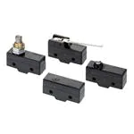


 工商网监
湘ICP备2023018690号
工商网监
湘ICP备2023018690号

