LYTSwitch-6 Family
Flyback CV/CC LED Driver IC with Integrated
High-Voltage Switch and FluxLink Feedback
Product Highlights
Highly Integrated, Compact Footprint
LYTSwitch-6
FB
GND
BPS
V
VOUT
Primary Switch
and Controller
S
EcoSmart™ – Energy Efficient
• Less than 30 mW no-load including line sense (without PF front end)
• Designs using LYTSwitch-6 easily meet Energy Star and all global
lighting energy efficiency regulations
• Low heat dissipation
D
SR
SR FET
FWD
• Up to 94% efficiency across full load range
• Incorporates a multi-mode Quasi-Resonant (QR) / CCM / DCM flyback
controller, high-voltage switch, secondary-side control and synchronous rectification driver
• Integrated FluxLink™, HIPOT-isolated, feedback link
• Exceptional CV/CC accuracy, independent of transformer design or
external components
• Adjustable accurate output current sense using external sense resistor
• PowiGaN™ technology – up to 100 W without heat sinks (LYT6079C
and LYT6070C)
IS
BPP
Optional
Current
Sense
Secondary
Control IC
PI-8375-112718
Figure 1. Typical Application/Performance.
Advanced Protection / Safety Features
•
•
•
•
•
Input line OV with auto-restart
Output fault OVP/UVP with auto-restart
Open SR FET gate detection
Input voltage monitor with accurate brown-in
Thermal foldback ensures that power continues to be delivered
(lower level) at elevated temperatures
Full Safety and Regulatory Compliance
•
•
•
•
Reinforced insulation
Isolation voltage >4000 VAC
100% production HIPOT compliance testing
UL1577 and TUV (EN60950 and EN62368) safety approved
Green Package
Figure 2. High Creepage, Safety-Compliant InSOP-24D Package.
Output Power Table
Product
2,3
277 VAC ± 15%
Open Frame1
• Halogen free and RoHS compliant
85-305 VAC
380 VDC /
450 VDC 2
Open Frame1 Open Frame1
Applications
LYT6063C/6073C
15 W
12 W
25 W
• Isolated off-line LED driver
• Smart LED lighting
• High-voltage flyback post regulator
LYT6065C/6075C
30 W
25 W
40 W
LYT6067C/6077C
50 W
45 W
60 W
LYT6068C
65 W
55 W
Description
The LYTSwitch™-6 series family of ICs dramatically simplifies the
development and manufacturing of off-line LED drivers, particularly
those in compact enclosures or with high efficiency requirements.
The LYTSwitch-6 architecture is revolutionary in that the devices
incorporate both primary and secondary controllers, with sense
elements and a safety-rated feedback mechanism into a single IC.
Close component proximity and innovative use of the integrated
communication link, FluxLink, permit accurate control of a secondaryside synchronous rectification MOSFET with Quasi-Resonant switching
of primary integrated high-voltage switch to maintain high efficiency
across the entire load range.
Product 2
LYT6078C
750 V PowiGaN Switch
75 W
65 W
90 W
LYT6079C
85 W
75 W
100 W
LYT6070C
95 W
85 W
110 W
Table 1. Output Power Table.
Notes:
1. Minimum continuous power in a typical non-ventilated and PCB size measured
at 40 °C ambient. Max output power is dependent on the design. With
condition that package temperature must be < 125 °C.
2. Package: InSOP-24D.
3. LYT606x ‒ 650 V MOSFET, LYT607x ‒ 725 V MOSFET.
www.power.com
June 2020
This Product is Covered by Patents and/or Pending Patent Applications.
�LYTSwitch-6
DRAIN
(D)
UNDER/OVER
INPUT VOLTAGE (V)
PRIMARY BYPASS
(BPP)
PRIMARY BYPASS
REGULATOR
ENABLE
ENABLE
FAULT
AUTO-RESTART
COUNTER
LINE
INTERFACE
GATE
RESET
BPP/UV
PRIM-CLK
UV/OV
OSCILLATOR/
TIMERS
GATE
tON(MAX)
JITTER
-
FAULT
OV/UV
PRIM/SEC
SecREQ
From
Secondary
Controller
SecPulse
DRIVER
Q
S
Q
R
PRIM/SEC
RECEIVER
CONTROLLER
SECLATCH
BPP/UV
LEB
IS
VSHUNT
VBP+
VILIM
GATE
GATE
tOFF(BLOCK)
PRIM-CLK
ILIM
+
VILIM
+
BPP
SenseFET
PRIMARY
BYPASS PIN
UNDERVOLTAGE
tOFF(BLOCK)
THERMAL
SHUTDOWN
Power
MOSFET
BPP/UV
PRIMARY
BYPASS PIN
CAPACITOR
SELECT AND
CURRENT
LIMIT
PRIMARY OVP
LATCH/
AUTO-RESTART
LATCH-OFF/
AUTO-RESTART
-
tON(MAX)
PI-8044g-041819
SOURCE
(S)
Figure 3. Primary Controller Block Diagram.
FORWARD
(FWD)
OUTPUT VOLTAGE
(VOUT)
SYNCRONOUS RECTIFIER DRIVE
(SR)
SR CONTROL
INH
VOUT
REGULATOR
VBPS
FORWARD
ENABLE
SR
SECONDARY
BYPASS
(BPS)
BPSUV
+
-
DETECTOR
+
S
Q
R
Q
VBPS(UVLO)(TH)
SR
THRESHOLD
QR
HANDSHAKE/
FAULT DETECTION
To
Primary
Receiver
SECONDARY
LATCH /
AUTO-RESTART
FEEDBACK
(FB)
+
INH
FEEDBACK
DRIVER
INH
DCM
CONTROL
-
QR
VREF
FEEDBACK
COMPENSATION
TsMAX
+
tOFF(MIN)
OSCILLATOR/
TIMER
-
tSECINH(MAX)
THERMAL
FOLDBACK
tSS(RAMP)
SECONDARY
GROUND
(GND)
ISENSE
(IS)
PI-8045h-080619
Figure 4. Secondary Controller Block Diagram.
2
Rev. K 06/20
www.power.com
�LYTSwitch-6
Pin Functional Description
ISENSE (IS) Pin (Pin 1)
Connection to the power supply output terminals. An external
current sense resistor should be connected between this and the
GND pin. If current regulation is not required, this pin should be tied
to the GND pin.
SECONDARY GROUND (GND) (Pin 2)
GND for the secondary IC. Note this is not the power supply output
GND due to the presence of the sense resistor between this and the
ISENSE pin.
FEEDBACK (FB) Pin (Pin 3)
Connection to an external resistor divider to set the power supply
output voltage.
V 13
BPP 14
NC 15
S 16-19
D 24
SECONDARY BYPASS (BPS) Pin (Pin 4)
Connection point for an external bypass capacitor for the secondary
IC supply.
PI-7877-022216
SYNCHRONOUS RECTIFIER DRIVE (SR) Pin (Pin 5)
Gate driver for external SR FET.
Figure 5. Pin Configuration.
OUTPUT VOLTAGE (VOUT) Pin (Pin 6)
Connected directly to the output voltage to provide current for the
controller on the secondary-side.
LYTSwitch-6 Functional Description
FORWARD (FWD) Pin (Pin 7)
The connection point to the switching node of the transformer output
winding providing information on the primary switch timing. Provides
power for the secondary-side controller when VOUT is below a threshold.
NC Pin (Pin 8-12)
Leave open. Should not be connected to any other pins.
Input Overvoltage (V) Pin (Pin 13)
A high-voltage pin connected to the AC or DC side of the input bridge
for detecting overvoltage conditions at the power supply input. This
pin should be tied to Source to disable OV protection.
PRIMARY BYPASS (BPP) Pin (Pin 14)
The connection point for an external bypass capacitor for the
primary-side supply. This is also the ILIM selection pin for choosing
standard ILIM or ILIM+1.
NC Pin (Pin 15)
Leave open or connect to SOURCE pin or BPP pin.
SOURCE (S) Pin (Pin 16-19)
These pins are the power switch source connection. It is also ground
reference for primary BYPASS pin.
DRAIN (D) Pin (Pin 24)
Power switch drain connection.
12 NC
11 NC
10 NC
9 NC
8 NC
7 FWD
6 VOUT
5 SR
4 BPS
3 FB
2 GND
1 IS
The LYTSwitch-6 combines a high-voltage power switch, along with
both primary-side and secondary-side controllers in one device.
The architecture incorporates a novel inductive coupling feedback
scheme using the package lead frame and bond wires to provide a
safe, reliable, and low-cost means to communicate accurate direct
sensing of the output voltage and output current on the secondary
controller to the primary controller.
LYTSwitch-6 is a Quasi-Resonant (QR) flyback controller that has the
ability to operate in continuous conduction mode (CCM). The
controller uses both variable frequency and variable current control
schemes. The primary controller consists of a frequency jitter
oscillator; a receiver circuit magnetically coupled to the secondary
controller, a current limit controller, 5 V regulator on the PRIMARY
BYPASS pin, audible noise reduction engine for light load operation,
bypass overvoltage detection circuit, a lossless input line sensing
circuit, current limit selection circuitry, over-temperature protection,
leading edge blanking, and a 650 V, 725 V or 750 V power switch.
The LYTSwitch-6 secondary controller consists of a transmitter circuit
that is magnetically coupled to the primary receiver, a constant
voltage (CV) and a constant current (CC) control circuit, a 4.4 V
regulator on the secondary SECONDARY BYPASS pin, synchronous
rectifier MOSFET driver, QR mode circuit, oscillator and timing
functions, thermal foldback control and a host of integrated
protection features.
Figure 3 and Figure 4 show the functional block diagrams of the
primary and secondary controller with the most important features.
3
www.power.com
Rev. K 06/20
�LYTSwitch-6
Primary Controller
PRIMARY BYPASS Pin Regulator
The PRIMARY BYPASS pin has an internal regulator that charges the
PRIMARY BYPASS pin capacitor to VBPP by drawing current from the
voltage on the DRAIN pin whenever the power switch is off. The
PRIMARY BYPASS pin is the internal supply voltage node. When the
power switch is on, the device operates from the energy stored in the
PRIMARY BYPASS pin capacitor.
In addition, there is a shunt regulator clamping the PRIMARY BYPASS
pin voltage to VSHUNT when the current is provided to the PRIMARY
BYPASS pin through an external resistor. This facilitates powering the
LYTSwitch-6 externally through a bias winding to decrease the
no-load consumption to less than 30 mW.
Primary Bypass ILIM Programming
LYTSwitch-6 has user programmable current limit (ILIM) settings
through the selection of PRIMARY BYPASS pin capacitor value. The
PRIMARY BYPASS pin can use a ceramic capacitor for decoupling the
internal supply of the device.
There are (2) programmable settings using 0.47 mF and 4.7 mF for
standard and increased ILIM settings respectively.
Primary Bypass Undervoltage Threshold
The PRIMARY BYPASS pin undervoltage circuitry disables the power
Switch when the PRIMARY BYPASS pin voltage drops below ~4.5 V
(VBPP - VBP(H)) in steady-state operation. Once the PRIMARY BYPASS
pin voltage falls below this threshold, it must rise back to VSHUNT to
re-enable turn-on of the power switch.
Primary Bypass Output Overvoltage Auto-Restart Function
The PRIMARY BYPASS pin has an OV protection auto-restart feature.
A Zener diode in parallel to the resistor in series with the PRIMARY
BYPASS pin capacitor is typically used to detect an overvoltage on the
primary bias winding to activate this protection mechanism. In the
event the current into the PRIMARY BYPASS pin exceeds ISD, the
device will disable the power switch switching for a time t AR(OFF). After
this time the controller will restart operation and attempt to return to
regulation.
This VOUT OV protection is also available as an integrated feature on
the secondary controller.
Over-Temperature Protection
The thermal shutdown circuitry senses the primary switch die
temperature. The threshold is typically set to TSD with TSD(H) hysteresis.
When the die temperature rises above this threshold the power switch
is disabled and remains disabled until the die temperature falls by
TSD(H) at which point it is re-enabled. A large hysteresis of TSD(H) is
provided to prevent over-heating of the PCB due to continuous fault
condition.
PI-8205-120516
1.05
Normalized ILIM (A)
The LYTSwitch-6 features variable frequency QR controller + CCM
operation for enhanced efficiency and extended output power
capability.
1.0
0.95
0.9
0.85
0.8
0.75
30
40
50
60
70
80
90
100
Steady-State Switching Frequency (kHz)
Figure 6. Normalized Primary Current vs. Frequency.
Current Limit Operation
The primary-side controller has a current limit threshold ramp that is
inversely proportional to time from the end of the last primary
switching cycle (i.e. from the time the primary switch turns off at the
end of a switching cycle).
The characteristic produces a primary current limit that increases as
the load increases (Figure 6).
This algorithm enables the most efficient use of the primary switch
with immediate response when a feedback switching cycle request is
received.
At high load, switching cycle have a maximum current approaching
100% ILIM gradually reduced to 30% of the full current limit as the
load reduces. Once 30% current limit is reached, there is no further
reduction in current limit (since this is low enough to avoid audible
noise) but the time between switching cycles will continue to increase
as load reduces.
Jitter
The normalized current limit is modulated between 100% and 95% at
a modulation frequency of fM this results in a frequency jitter of ~7 kHz
with average frequency of ~100 kHz.
Auto-Restart
In the event a fault condition occurs such as an output overload,
output short-circuit, or external component/pin fault, the LYTSwitch-6
enters into auto-restart (AR) operation. In auto-restart the power
switch switching is disabled for t AR(OFF). There are 2 ways to enter
auto-restart:
1. Continuous secondary requests at above the overload detection
frequency (~110 kHz) for longer than 80 ms.
2. No requests for switching cycles from the secondary for > tAR(SK).
4
Rev. K 06/20
www.power.com
�LYTSwitch-6
The second was included to ensure that if communication is lost, the
primary tries to restart again. Although this should never be the case
in normal operation, this can be useful in the case of system ESD
events for example where a loss of communication due to noise
disturbing the secondary controller, the issue is resolved when the
primary restarts after an auto-restart off time.
P: Primary Chip
S: Secondary Chip
Start
P: Powered Up, Switching
S: Powering Up
The auto-restart is reset as soon as an AC reset occurs.
SOA Protection
In the event there are two consecutive cycles where the ILIM is
reached within the blanking time and current limit delay time
(including leading edge current spike ~500 ns), the controller will skip
approximately 2.5 cycles or ~25 ms (based on full frequency of
100 kHz). This provides sufficient time for reset of the transformer
during start-up into large capacitive loads without extending the
start-up time.
Input Line Voltage Monitoring
The INPUT OVERVOLTAGE pin is used for input overvoltage sensing
and protection.
A sense resistor is tied between the high-voltage DC bulk capacitor
after the bridge (or to the AC side of the bridge rectifier for fast AC
reset) and the INPUT OVERVOLTAGE pin to enable this functionality.
This pin functionality can be disabled by shorting INPUT
OVERVOLTAGE pin to primary Source.
Primary/Secondary-Side Handshake
At start-up, the primary-side initially switches without any feedback
information (this is very similar to the operation of a standard
TOPSwitch™, TinySwitch™ or LinkSwitch™ controllers).
If no feedback signals are received during the auto-restart on-time
(t AR), the primary goes into auto-restart mode. Under normal
conditions, the secondary controller will power-up via the FORWARD
pin or from OUTPUT VOLTAGE pin and take over control. From this
point onwards the secondary controls switching.
If the primary stops switching or does not respond to cycle requests
from the secondary during normal operation (when the secondary
has control), the handshake protocol is initiated to ensure that the
secondary is ready to assume control once the primary begins to
switch again. An additional handshake is also triggered if the
secondary detects that the primary is providing more cycles than
were requested.
The most likely event that could require an additional handshake is
when the primary stops switching as the result of a momentary line
brown-out event. When the primary resumes operation, it will default
into a start-up condition and attempt to detect handshake pulses
from the secondary.
If the secondary does not detect that the primary responds to
switching requests for 8 consecutive cycles, or if the secondary
detects that the primary is switching without cycle requests for 4
or more consecutive cycles, the secondary controller will initiate a
second handshake sequence. This provides additional protection
against cross-conduction of SF FET while the primary is switching.
P: Auto-Restart
S: Powering Up
tAR(OFF)
S: Has powered
up within tAR
No
P: Goes to Auto-Restart Off
S: Bypass Discharging
Yes
tAR
P: Switching
S: Sends Handshaking Pulses
P: Has Received
Handshaking
Pulses
No
P: Continuous Switching
S: Doesn’t Take Control
No
P: Not Switching
S: Doesn’t Take Control
Yes
P: Stops Switching, Hands
Over Control to Secondary
S: Has Taken
Control?
Yes
End of Handshaking,
Secondary Control Mode
PI-8876-110818
Figure 7. Primary-Secondary Handshake Flow Chart.
This protection mode also prevents an output overvoltage condition
in the event that the primary is reset while the secondary is still in
control.
Wait and Listen
When the primary resumes switching after initial power-up recovery
from input line voltage fault or an auto-restart event, it will assume
control and require a successful handshake to relinquish control to
the secondary controller.
5
www.power.com
Rev. K 06/20
�LYTSwitch-6
Audible Noise Reduction Engine
The LYTSwitch-6 features and active audible noise reduction mode
wherein the controller (via a “frequency skipping” mode of operation)
avoids the resonant band (where the mechanical structure of the
power supply is most likely to resonate ‒ increasing noise amplitude)
between 5 kHz and 12 kHz ‒ 200 ms and 83 ms period respectively. If a
secondary controller request occur within this window from the last
conduction cycle, the gate drive of the power switch is inhibited.
Secondary Controller
As shown in the block diagram in Figure 4, the IC is powered through
regulator 4.4 V (VBPS) by either VOUT or FW. The SECONDARY
BYPASS pin is connected to an external decoupling capacitor and fed
internally from the regulator block.
The FORWARD pin also connects to the negative edge detection
block used for both handshaking and timing to turn on the SF FET
connected to the SYNCHRONOUS RECTIFIER DRIVE pin. The
FORWARD pin voltage is used to determine when to turn off the
SF FET in discontinuous mode operation. This is when the voltage
across the RDS(ON) of the SR FET drops below zero volts.
In continuous conduction mode (CCM) the SR FET is turned off when
the feedback pulse is sent to the primary to demand the next
switching cycle, providing excellent synchronous operation, free of
the any overlap for the FET turn-off.
The mid-point of an external resistor divider network between the
OUTPUT VOLTAGE and SECONDARY GROUND pins is tied to the
FEEDBACK pin to regulate the output voltage. The internal voltage
comparator reference voltage is VREF (1.265 V).
The external current sense resistor connected between ISENSE and
SECONDARY GROUND pins to regulate the output current in constant
current regulator mode.
Minimum Off-Time
The secondary controller initiates cycle request using the inductive
connection to the primary. The maximum frequency of the
secondary-cycle requests is limited by a minimum cycle off-time of
tOFF(MIN). This is in order to ensure that there is sufficient reset time
after the primary conduction to deliver energy to the load.
Maximum Switching Frequency
The maximum switch request frequency of the secondary controller
is fSREQ.
Frequency Soft-Start
At start-up the primary controller is limited to a maximum switching
frequency of fSW and 75% of the maximum programmed current limit
at the switch-request frequency of 100 kHz.
The secondary controller temporarily inhibits the FEEDBACK short
protection threshold (VFB(OFF)) until the end of the soft-start (tSS(RAMP))
timer. After hand-shake is completed the secondary controller
linearly ramps up the switching frequency from fSW to fSREQ over the
tSS(RAMP) time period.
In the event of a short-circuit or overload at start-up, the device will
regulate directly into CC (constant-current mode). The device will go
into auto-restart (AR), if the output voltage does not rise above the
VO(AR) threshold before the expiration of the VOUT AR timer (tFB(AR)) after
handshake has occurred.
The secondary controller enables the FEEDBACK pin short protection
mode (VFB(OFF)) at the end of the tSS(RAMP) time period. If the output
short maintains the FEEDBACK pin to be below short-circuit threshold
the secondary will stop requesting pulses to trigger an auto-restart
cycle.
If output voltage reaches regulation within the tSS(RAMP) time period,
the frequency ramp is immediately aborted and the secondary
controller is permitted to go full frequency. This will allow the
controller to maintain regulation in the event of a sudden transient
loading soon after regulation is achieved. The frequency ramp will
only be aborted if quasi-resonant detection programming has already
occurred.
Maximum Secondary Inhibit Period
Secondary-cycle requests to initiate primary switching are inhibited to
maintain operation below maximum frequency and ensure minimum
off-time. Besides these constraints, secondary-cycle requests are
also inhibited during the “ON” time cycle of the primary switch (time
between the cycle request and detection of FORWARD pin falling
edge). The maximum time-out in the event a FORWARD pin falling
edge is not detected after a cycle requested is ~30 ms.
Thermal Foldback
When the secondary controller die temperature reaches 124 °C, the
output power is reduced by reducing the constant current reference
threshold (see Figure 8).
Maximum Output Current (%)
As an additional safety measure the primary will pause for an
auto-restart on-time, t AR (~82 ms), before switching. During this
“wait” time, the primary will “listen” for secondary requests. If it sees
two consecutive secondary requests, separated by 30 ms, the primary
will enter secondary control and begins switching in slave mode. If
no such pulses occur during the t AR “wait” period, the primary will
begin switching under primary control until handshake pulses are
received.
100
70
109
124
Secondary Controller Die
Temperature (ºC)
PI-8376b-080619
Figure 8. Maximum Output Current vs. Secondary Die Temperature.
6
Rev. K 06/20
www.power.com
�LYTSwitch-6
Output Voltage Protection
In the event the sensed voltage on the FEEDBACK pin is 2% higher
than the regulation threshold, a bleed current of ~2.5 mA (3 mA max)
is applied on the OUTPUT VOLTAGE pin (weak bleed). This bleed
current increases to ~200 mA in the event the FEEDBACK pin voltage
is raised to beyond ~10% (strong bleed) of the internal FEEDBACK
pin reference voltage. The current sink on the OUTPUT VOLTAGE pin
is intended to discharge the output voltage for momentary overshoot
events. The secondary does not relinquish control to the primary
during this mode of operation.
If the voltage on the FEEDBACK pin is sensed to be 20% higher than
the regulation threshold, a command is sent to the primary to begin
an auto-restart sequence. This integrated VOUT OVP can be used
independently from the primary sensed OVP or in conjunction.
FEEDBACK Pin Short Detection
If the sensed FEEDBACK pin voltage is below VFB(OFF) at start-up, the
secondary controller will complete the handshake to take control of
the primary complete tSS(RAMP) and will stop requesting cycles to initiate
auto-restart (no cycle requests made to primary for longer than t AR(SK)
second triggers auto-restart).
During normal operation, the secondary will stop requesting pulses
from the primary to initiate an auto-restart cycle when the FEEDBACK
pin voltage falls below VFB(OFF) threshold. The deglitch filter on the
protection mode is less than 10 ms. By this mechanism, the secondary
will relinquish control after detecting the FEEDBACK pin is shorted to
ground.
Auto-Restart Thresholds
The OUTPUT VOLTAGE pin includes a comparator to detect when the
output voltage falls below V VO(AR) of V VO, for a duration exceeding
tVOUT(AR). The secondary controller will relinquish control when this
fault condition is sensed. This threshold is meant to limit the range of
constant current (CC) operation.
SECONDARY BYPASS Overvoltage Protection
The LYTSwitch-6 secondary controller features SECONDARY BYPASS
pin OV feature similar to PRIMARY BYPASS pin OV feature. When the
secondary is in control: in the event the SECONDARY BYPASS pin
current exceeds IBPS(SD) (~7 mA) the secondary will send a command
to the primary to initiate an auto-restart off-time (t AR(OFF)) event.
Output Constant Current
The LYTSwitch-6 regulates the output current through an external
current sense resistor between the ISENSE and SECONDARY
GROUND pins where the voltage generated across the resistor is
compared to internal of ISV(TH) (~35 mV). If constant current
regulation is not required, the ISENSE pin must be tied to
SECONDARY GROUND pin.
SR Static Pull-Down
To ensure that the SR gate is held low when the secondary is not in
control, the SYNCHRONOUS RECTIFIER DRIVE pin has a nominally
“ON” device to pull the pin low and discharge any voltage
accumulation on the SR gate due to capacitive coupling from the
FORWARD pin.
Open SR Protection
The secondary controller has a protection mode to ensure the
SYNCHRONOUS RECTIFIER DRIVE pin is connected to an external
MOSFET to protect against an open SYNCHRONOUS RECTIFIER
DRIVE pin system fault. At start-up the controller will sink a current
from the SYNCHRONOUS RECTIFIER DRIVE pin; an internal threshold
will correlate to a capacitance of 100 pF. If the capacitance on the
SYNCHRONOUS RECTIFIER DRIVE pin is below 100 pF (the resulting
voltage is below the reference voltage), the device will assume the
SYNCHRONOUS RECTIFIER DRIVE pin is “open” and there is no FET
to drive. If the pin capacitance detected to be above 100 pF (the
resulting voltage is above the reference voltage), the controller will
assume an SR FET is populated.
In the event the SYNCHRONOUS RECTIFIER DRIVE pin is detected to
be open, the secondary controller will stop requesting pulses to the
primary to initiate auto-restart.
If the SYNCHRONOUS RECTIFIER DRIVE pin is tied to ground at
start-up, the SR drive function is disabled and the open SYNCHRONOUS
RECTIFIER DRIVE pin protection mode is also disabled.
Intelligent Quasi-Resonant Mode Switching
In order to improve conversion efficiency and reduce switching
losses, the LYTSwitch-6 features a means to force switching when the
voltage across the primary switch is near its minimum voltage when
the converter operates in discontinuous conduction mode (DCM).
This mode of operation automatically engages in DCM and disabled
once the converter moves to continuous-conduction mode (CCM).
Rather than detecting the magnetizing ring valley on the primaryside, the peak voltage of the FORWARD pin voltage as it rises above
the output voltage level is used to gate secondary request to initiate
the switch “ON” cycle in the primary controller.
The secondary controller detects when the controller enters in
discontinuous-mode and opens secondary cycle request windows
corresponding to minimum switching voltage across the primary
power switch.
Quasi-Resonant (QR) mode is enabled for 20 msec after DCM is
detected or ring amplitude (pk-pk) >2 V. Afterward QR switching is
disabled, at which point switching may occur at any time a secondary
request is initiated.
The secondary controller includes blanking of ~1 ms to prevent false
detection of primary “ON” cycle when the FORWARD pin rings below
ground.
7
www.power.com
Rev. K 06/20
�PI-8569-010318
FORWARD Pin Voltage
LYTSwitch-6
Request Window
Output Voltage
Primary VDS
Time
Time
Figure 9. Intelligent Quasi-Resonant Mode Switching.
8
Rev. K 06/20
www.power.com
�LYTSwitch-6
Application Example
C12
3.3 nF
250 VAC
L3
560 µH
D16
S1J-13-F
C9
1000 pF
630 V
D1
ES2_J_LTP
9
T1
EE13
5
BR1
UD4KB100
1000 V
VR1
BZD27C200P
200 V
R17
510 kΩ
R4
2.0 MΩ
7
2
4
R30
1.62 kΩ
1%
1/16 W
D11
DFLU1400-7
D17
ES2J-LTP
5
R22
47 Ω
C2
220 nF
450 V
4
C3
330 nF
450 V
C19
330 pF
50 V
TP2
C4
68 µF
450 V
D7
DFLR1200-7
200 V
D
V
SR
R45
2.00 MΩ
1%
FWD
R47
4.7 kΩ
C13
2.2 µF
25 V
GND
C1
100 nF
630 VDC
C15
10 µF
25 V
FL3
R24
6.2 Ω
1%
FB
RV1
275 VAC
F1
3.15 A
TP3
C37
1.5 nF
200 V
FL4
D8
DFLR1600-7
600 V
BPS
90 - 265
VAC
L2
20 mH 3
80 V, 580 mA
R29
102 kΩ
1%
1/8 W
D10
STTH3R06S
600 V
FL2
2
R46
20 Ω
VR2
BZD27C200P
200 V
C18
100 µF
100 V
C14
R48
100 Ω 100 pF
1/2 W 1 kV
TP1
1
C16
100 µF
100 V
T2
1 RM10 FL1
CONTROL
VOUT
R18
10 kΩ
C10
22 µF
16 V
S
BPP
C11
4.7 µF
50 V
LYTSwitch-6
U4
LYT6068C
R43
0.062 Ω
1%
1/2 W
IS
D13
US1B
PI-8576-012618
RTN
TP4
Figure 10. Schematic DER-657, 46.4 W, 80 V, 0.58 A for Universal External LED Driver Application.
The circuit shown on Figure 10 is a 46 W isolated flyback power
supply with a single-stage power factor correction circuit for LED
lighting applications. It provides an accurately regulated 80 V, 580 mA
output for multi-LED-string applications where a post regulator is
used − such as in RGBW smart-lighting fixtures. The design is also
ideal for single string applications as it also provides a constant
580 mA output current with accurate regulation and no line-induced
ripple across a load-voltage range of 80 V to 20 V. The circuit is
highly efficient offering accurate load regulation and is stable over
line (90 VAC to 265 VAC). The circuit also delivers a PF of greater
than 0.9 with less than 20% A-THD (measured at 230 VAC).
Input Stage
Fuse F1 provides open-circuit protection which isolates the circuit
from the input line in the event of catastrophic component failures.
Varistor RV1 clamps any voltage spikes to protect the circuitry located
after the fuse from damage due to overvoltage caused by a line
transient or surge. Bridge diode BR1 rectifies the AC line voltage and
provides a full-wave rectified DC voltage across the input film capacitors
C2 and C3. The EMI filter is a 2-stage LC circuit comprising C1, L2,
C2, L3, and C3 and suppress differential and common mode noise
generated from the PFC and flyback switching stages.
Primary Flyback Stage
The bulk capacitor C4 completes the input stage. It filters the line
ripple voltage and provides energy storage. This component also
filters differential current, further reducing conducted EMI. The input
stage provides a DC voltage to the flyback converter. One end of the
primary winding of transformer (T2) is connected to the positive
terminal of the bulk capacitor (C4) while the other is connected to the
DRAIN pin of the integrated 650 V power switch in the LYTSwitch-6
IC (U1). A low-cost RCD primary clamp made up of D8, R46, R17 and
C9 limits the voltage spike developed across the switch that is caused
by the transformer leakage inductance. The RCD primary clamp also
reduces radiated and conducted EMI.
In order to provide line overvoltage detection, the bulk capacitor
voltage is sensed and converted into a current by the INPUT
VOLTAGE pin resistors R4 and R45. The INPUT VOLTAGE pin line
overvoltage threshold current (IOV-) determines the input overvoltage
shutdown point.
The LYTSwitch-6 IC is self-starting, using an internal high-voltage
current source to charge the PRIMARY BYPASS pin capacitor (C11)
when AC is first applied. During normal operation the primary-side
circuitry is powered from an auxiliary winding on transformer T2.
A value of 4.7 µF was selected for the BPP capacitor (C11) to select
increased-current-limit operation. During normal operation the
output of the auxiliary (bias) winding is rectified using diode D7 and
filtered using capacitor C10. Resistor R18 limits the current being
supplied to the PRIMARY BYPASS pin.
Power Factor Correction Stage
The Power Factor Correction circuit comprises an inductor (T1) in
series with blocking diodes (D1 and D17) and is connected to the
DRAIN pin of the LYTSwitch-6 IC. High PF is achieved using a
Switched Valley-Fill Single Stage PFC (SVF S2PFC) circuit operating in
discontinuous conduction mode (DCM). In DCM the switched current
from inductor T1 shapes the input current waveform to create a
quasi-sinusoid when the rectified voltage on C3 is less than the DC
voltage on C4, this results in a high power factor.
During switch on-time, energy is stored in the PFC inductor (T1) and
the leakage inductance of the flyback transformer (T2). During
switch off-time, the energy from both the PFC and flyback inductors
is transferred to the secondary-side through the flyback transformer
T2. Diode D16 isolates the rectified AC input on C3 from C4 and
9
www.power.com
Rev. K 06/20
�LYTSwitch-6
provides current path for the charging of the bulk capacitor C4 −
especially at low-line, which improves efficiency. Free-wheel diodes
D1 and D17 provide a current path for the energy stored in the PFC
inductor that must be transferred to the secondary-side during switch
off-time. The series connection of D1 and D17 are able to withstand
the resonant voltage ring from the PFC inductor when the switch
turns off.
During a no-load or light load condition (84% increasing to >89% for the
largest device.
3. Transformer primary inductance tolerance is ±10%.
4. Reflected output voltage (VOR) is set to maintain KP = 0.8 at
minimum input voltage for universal line, and KP = 1 for high
input line (only) designs.
5. Maximum conduction loss for adapters is limited to 0.6 W and to
0.8 W for open frame designs.
6. Increased current limit is selected for peak and open-frame
power columns, while standard current limit is used for adapter
columns.
7. The part is board-mounted with SOURCE pins soldered to a
sufficient area of copper and/or a heat sink to keep the SOURCE
pin temperature ≤110 °C.
8. Ambient temperature limit is 50 °C for open frame designs and
40 °C for sealed adapters.
9. Below a value of 1, KP is the ratio of ripple to peak primary
current. To prevent reduced power delivery, due to premature
termination of switching cycles, a transient KP limit of ≥0.6 is
specified. This prevents the initial current limit (IINT) from being
exceeded at switch turn-on.
10. LYTSwitch-6 parts are unique in that the designer can set the
switching frequency between 25 kHz to 95 kHz by adjusting
transformer design. One way to lower device temperature is to
design the transformer to reduce switching frequency; a good
starting point is 50 kHz.
Primary-Side Overvoltage Protection
Primary-side output overvoltage protection provided by the
LYTSwitch-6 IC uses an internal protection that is triggered by a
threshold current of ISD into the PRIMARY BYPASS pin. For the
bypass capacitor to be effective as a high frequency filter, the
capacitor should be located as close as possible to the SOURCE and
PRIMARY BYPASS pins of the device.
The primary sensed OVP function can be realized by connecting a
series combination of a Zener diode, a resistor and a blocking diode
from the rectified and filtered bias-winding-voltage supply to the
PRIMARY BYPASS pin (see Figure 11-a). The rectified and filtered bias
winding output voltage may be higher than anticipated (up to
2 times the desired value) and is dependent on the coupling of the
bias winding to the output winding and the resultant ringing of the
bias winding voltage waveform. It is recommended that the rectified
bias winding voltage be measured. Ideally this measurement should
be made at the lowest input voltage and with maximum load applied
the output. This measured voltage should be used to select the
components required to achieve primary sensed OVP. It is
recommended that a Zener diode is selected with a clamping voltage
approximately 6 V lower than the rectified bias winding voltage at
which OVP is expected to be triggered. A forward voltage drop of 1 V
can be assumed for the blocking diode. A small-signal standard
recovery diode is recommended for this task. The blocking diode
prevents any reverse current from charging the bias capacitor during
start-up. Finally, the value of the series resistor required can be
calculated such that a current higher than ISD will flow into the
PRIMARY BYPASS pin during an output overvoltage event.
Secondary-Side Overvoltage Protection
Secondary-side output overvoltage protection is provided by the
LYTSwitch-6 IC which uses an internal auto-restart circuit triggered
by an input current into the SECONDARY BYPASS pin exceeding a
threshold of IBPS(SD). The direct sensed output OVP function can
be realized by connecting a Zener diode from the output to the
SECONDARY BYPASS pin. The Zener diode voltage needs to be the
10
Rev. K 06/20
www.power.com
�LYTSwitch-6
+VBULK
DBIAS
Zener
OVP
NB
CBIAS
VOUT
RZ
FB
VZ
DB
RBP
DB
V
GND
D
BPS
LYTSwitch-6
SR
VRZ
FB
CBPS
RZ
FWD
CIN
LYTSwitch-6
Primary Switch
and Controller
Secondary
Control IC
S
BPP
IS
PI-8579-112718
PI-8580-012318
RTN
b. Secondary-side OVP with High Current Pushed into BPS via Zener V Z and
Resistor R Z.
a. Primary-side OVP with High Current Pushed into BPP via Zener V Z.
Figure 11. Output Overvoltage Protection Circuits.
CY
RSN
CSN
RS
CSR
CFB
COUT
RSR
CPH
RPH
DSN
RLS1
RFB(LOWER)
SR FET
DBIAS
V
GND
FWD
RLS
LYTSwitch-6 D
SR
C2
Primary Switch
and Controller
FB
CBPS
RFWD
BPS
CBIAS
VOUT
RIS
S
(-)
VOUT
RFB(UPPER)
+VBULK
BPP
RBP
IS
Secondary
Control IC
CBPP
PI-8581-112718
RTN
Figure 12. Typical Schematic of LYTSwitch-6 Flyback Power Supply (DC-DC Stage).
absolute value of (1.25 x VOUT) – (4.4 V − SECONDARY BYPASS pin
voltage). It is necessary to add a low value resistor, in series with the
OVP Zener diode to limit the maximum current into the SECONDARY
BYPASS pin (see Figure 11-b.)
Selecting Critical External Components
The schematic in Figure 12 shows the essential external components
required for a working single output LYTSwitch-6 based power supply.
The selection criteria for these components is as follows:
11
www.power.com
Rev. K 06/20
�LYTSwitch-6
Primary-Side Components
PRIMARY BYPASS Pin Capacitor (CBPP)
This capacitor works as the supply decoupling capacitor for the
internal primary-side controller and also determines current limit for
the internal switch. 4.7 µF or 0.47 µF capacitance will select
INCREASED or STANDARD current limits respectively. Though
electrolytic capacitors can be used, often surface mount multi-layer
ceramic capacitors are preferred for use on double-sided boards as
they allow the capacitors to be placed close to the IC. At least 10 V,
0805 or larger size rated X5R or X7R dielectric capacitors are
recommended to ensure that minimum capacitance requirements are
met. The ceramic capacitor type designations, such as X7R, X5R
from different manufacturers or different product families do not
have the same voltage coefficients. It is recommended that capacitor
data sheets be reviewed to ensure that the selected capacitor will not
have more than 20% drop in capacitance at 5 V. Do not use Y5U or
Z5U / 0603 rated MLCC due to this type of SMD ceramic capacitor has
very poor voltage and temperature coefficient characteristics.
Line Overvoltage / Brown-In Sense Resistor (RLS)
Both line overvoltage and brown-in voltage are sensed by the INPUT
VOLTAGE pin. The current from the DC input bus is monitored via
resistor RLS and compared to an internal current threshold.
Typical value range for RLS is in the range of 3.8 MΩ to 4 MΩ. RLS is
approximately equal to VLOV × 1.414 / IOV-.
VLOV is the input line voltage at which the power supply will stop
switching because the overvoltage threshold (IOV-) is exceeded.
Switching will be re-enabled when line overvoltage hysteresis (IOV(H))
is reached. Line OV (VLOV) is approximately equal to IOV- × RLS / 1.414.
The power supply will turn on once the brown-in threshold (IUV+) is
exceeded. Brown-in voltage is approximately equal to IUV+ x RLS /
1.414.
External Bias Supply Components (DBIAS, CBIAS, RBP)
The LYTSwitch-6 IC has an internal bypass regulator from the
DRAIN pin of the primary-side switch to the PRIMARY BYPASS pin.
This internal regulator is active during the switch off-time and keeps
the PRIMARY BYPASS pin voltage from dropping below 5 V. This
ensures that the IC will operate normally especially during start-up
time. During start-up, the IC is powered from the internal regulator.
When the output voltage has risen sufficiently, the primary controller
will draw power from the external bias supply via the auxiliary
winding rather than from the internal tap. This will reduce energy
consumption as the auxiliary supply is at much lower voltage than the
tap (which is driven by the high-voltage of the DRAIN pin). If the
coupling between the bias winding and secondary winding is poor,
the bias supply voltage may can drop significantly during no-load
operation and may not be able to supply current to the PRIMARY
BYPASS pin and keep the internal regulator off. If this condition
causes the internal tap to turn on, no-load power consumption will
increase. It is therefore recommended that the bias voltage be set
close to the maximum of 12 V. Higher voltage may also increase
no-load power consumption. For the bias supply, there is a trade-off
between using a standard-recovery diode and a fast signal diode for
the bias winding rectifier diode, DBIAS. The standard recovery diode
will tend to give lower radiated EMI while the fast diode will reduce
no-load power consumption. Since LYTSwitch-6 ICs inherently use
very little power, it is recommended that the standard recovery diode
is used for the bias supply, trading a small increase in power
dissipation for improved EMI performance.
A 22 µF 50 V low ESR aluminum electrolytic capacitor is recommended
for the bias supply filter, CBIAS. A low ESR electrolytic capacitor
reduces no-load power consumption. Use of a ceramic surface mount
capacitor is not recommended as this may cause audible noise due to
piezoelectric excitation of the ceramic capacitors mechanical structure.
To ensure minimum no-load input power and high full load efficiency,
resistor RBP (Figure 12) should be selected such that the current
through this resistor is higher than the PRIMARY BYPASS pin supply
current.
The PRIMARY BYPASS pin supply can be calculated as shown below;
f SW
ISSW = b 132 K l × ^ IS2 - IS1 h + IS1
Where;
ISSW: PRIMARY BYPASS pin supply current at operating switching
frequency
fSW: Operating switching frequency (kHz)
IS1: Non-switching PRIMARY BYPASS pin supply current (refer to
data sheet specification tables)
IS2: PRIMARY BYPASS pin supply current at 132 kHz (refer to
data specification sheet)
The PRIMARY BYPASS pin voltage will be ~5.3 V if the bias current is
higher than PRIMARY BYPASS pin supply current. A PRIMARY
BYPASS pin voltage of ~5.0 V, indicates that the current through
RBP is less than the PRIMARY BYPASS pin supply current and the IC is
drawing current from the DRAIN pin. Ensure that the voltage on the
PRIMARY BYPASS pin never falls below 5.3 V − except during start-up.
To determine maximum value of RBP;
R BP = [V BIAS ( NO – LOAD ) - V BPP ] / I SSW;
where VBPP = 5.3 V.
Clamp Network Across Primary Winding
(DSN, RS, RSN, and C SN)
Figure 13, shows the low cost R2CD clamp which is used in most low
power circuits. For higher power designs, a Zener clamp or an R2CD
plus Zener clamp can be used to achieve better efficiency. It is
advisable to limit the peak Drain voltage to 90% of BVDSS under worstcase conditions (maximum input voltage, maximum overload power or
output short-circuit). The clamp diode, DSN shown in Figure 13 must
be either a standard recovery glass passivated diode or a fast
recovery type with a reverse recovery time of less than 500 ns. Use
of standard recovery switch passivated diodes allows the recovery of
some of the clamp energy from each cycle and improves average
efficiency. The diode momentarily conducts each time the primary
switch inside the LYTSwitch-6 IC turns off and energy from the
leakage reactance is transferred to the clamp capacitor CSN. Resistor
RS, which is in the series path, acts as a damper preventing excessive
ringing due to resonance between the leakage reactance and the
clamp capacitor CSN. Resistor RS dissipates the energy stored in
capacitor CSN. Designs employing different sized LYTSwitch-6 devices
will have different peak primary currents and leakage inductances
and will therefore result in different amounts of leakage energy.
Capacitor CSN, RSN and RS must therefore be optimized for each
design. As a general rule the value of capacitor CSN should be
minimized and the value of resistors RSN and RS maximized, while still
meeting the 90% derating of the BVDSS limit. RS should be
sufficiently large to damp the ring, but small enough to prevent the
drain voltage from rising too far. A ceramic capacitor that uses a
dielectric such as Z5U if used as the CSN capacitor in the clamp circuit
may generate audible noise, so the use of a polyester film type
capacitor is preferred.
12
Rev. K 06/20
www.power.com
�LYTSwitch-6
Common Primary Clamp Configurations
R2CD
RSN
Zener
RSN
VRCLAMP
CSN
Rs
R2CD + Zener
DCLAMP
DCLAMP
DCLAMP
RS
RS
D
VRCLAMP
CSN
D
PI-8582-011218
D
PI-8584-011218
PI-8583-011218
Figure 13. Recommended Primary Clamp Components.
Primary Clamp Circuit
R2CD
Zener
R2CD + Zener
Component Cost
Low
Medium
High
No-Load Input Power
High
Low
Medium
Light-Load Efficiency
Low
High
Medium
EMI Suppression
High
Low
Medium
Benefits
Table 2.
Benefits of Primary Clamp Circuits.
Secondary-Side Components Driving LYTSwitch-6
SECONDARY BYPASS Pin Capacitor (CBPS)
This capacitor works as a voltage supply decoupling capacitor for the
integrated secondary-side controller. A surface mount, 2.2 mF, 10 V /
X7R or X5R / 0805 or larger size, multi-layer ceramic capacitor is
recommended for this application. The SECONDARY BYPASS pin
voltage needs to reach 4.4 V before the output voltage reaches its
target voltage. A significantly higher value of SECONDARY BYPASS
pin capacitor may prevent this from occurring and induce an output
voltage overshoot during start-up. Values lower than 1.5 µF may not
be provide sufficient energy storage, leading to unpredictable device
operation. The capacitor must be located adjacent to the IC pins. At
least 10 V is recommended voltage rating to give enough margin from
BPS voltage, and 0805 size is necessary to guarantee the actual value
in operation since the capacitance of ceramic capacitors drops
significantly with applied DC voltage especially with small package
SMD such as 0603. 6.3 V / 0603 / X5U or Z5U type of MLCC is not
recommended for this reason. The ceramic capacitor type designations,
such as X7R, X5R from different manufacturers or different product
families do not have the same voltage coefficients. It is recommended
that capacitor data sheets be reviewed to ensure that the selected
capacitor will not have more than 20% drop in capacitance at 4.4 V.
Capacitors with X5R or X7R dielectrics should be used for best results.
13
www.power.com
Rev. K 06/20
�LYTSwitch-6
FORWARD Pin Resistor (RFWD)
The FORWARD pin is connected to the drain terminal of the
synchronous rectifier MOSFET (SR FET). This pin is used to monitor
the Drain voltage of the SR FET to precisely control turn-on and
turn-off of the device. This pin is also used to charge the SECONDARY
BYPASS pin capacitor whenever the output voltage falls below the
SECONDARY BYPASS pin voltage. The use of a 47 Ω, 5% resistor is
recommended to ensure sufficient IC supply current and works well
across a wide range of output voltages. A different resistor value will
interfere with the timing of the synchronous rectifier drive and should
not be used. Care must be taken to ensure that the voltage at the
FORWARD pin never exceeds its absolute maximum voltage rating.
If the FORWARD pin voltage exceeds the FORWARD pin absolute
maximum voltage, the IC will be damaged. Figures 14, 15, 16 and 17
below show examples of unacceptable and acceptable FORWARD pin
voltage waveforms. VD is forward voltage drop across the SR FET.
0V
VSRTH
VD
t1
t2
PI-8394-080917
Figure 16. Unacceptable FORWARD Pin Waveform Before Handshake with Body
Diode Conduction During Flyback Cycle.
Note:
If t1 + t2 = 1.5 ms ± 50 ns, the controller may fail the handshake and
trigger a primary bias winding OVP latch-off.
0V
VSRTH
VD
PI-8392-082317
Figure 14. Unacceptable FORWARD Pin Waveform After Handshake with
SR FET Conduction During Flyback Cycle.
0V
VSRTH
VD
PI-8395-121117
Figure 17. Acceptable FORWARD Pin Waveform Before Handshake with Body
Diode Conduction During Flyback Cycle.
0V
VSRTH
VD
PI-8393-080917
Figure 15. Acceptable FORWARD Pin Waveform After Handshake with
SR FET Conduction During Flyback Cycle.
FEEDBACK Pin Divider Network (RFB(UPPER), RFB(LOWER))
A suitable resistive voltage divider should be connected from the
output of the power supply to the FEEDBACK pin of the LYTSwitch-6
IC and sized such that at the desired output voltage, the FEEDBACK
pin will be at 1.265 V. A decoupling capacitor (CFB) of 330 pF is
recommended and should be connected from the FEEDBACK pin to
SECONDARY GROUND pin. CFB acts as a decoupling capacitor for the
FEEDBACK pin to prevent switching noise from affecting IC operation.
SR FET Operation and Selection
Although a simple diode rectifier and snubber is effective, the use
of a SR FET significantly improves efficiency. The secondary-side
controller turns the SR FET on at the beginning of the flyback cycle.
The gate of the SR FET should be tied directly to the SYNCHRONOUS
RECTIFIER DRIVE pin of the LYTSwitch-6 IC (no additional resistors
should be connected to the gate drive of the SR FET). The SR FET is
turned off when its VDS reaches 0 V. The SR FET driver uses the
SECONDARY BYPASS pin as its supply rail; this voltage is typically 4.4 V.
A FET with a high gate threshold voltage is not therefore appropriate
for this application; FETs with a threshold voltage of 1.5 − 2.5 V are
ideal. MOSFETs with a threshold voltage as high as 4 V may also be
used provided that the data sheet specifies RDS(ON) across temperature
for a gate voltage of 4.5 V.
There is a short delay between the start of the flyback cycle and the
turn-on of the SR FET. During this time, the body diode of the
SR FET will conduct. If an external Schottky diode is connected in
parallel, current flows mostly through the Schottky diode. A parallel
Schottky diode will therefore increase efficiency. A 1 A surface-
14
Rev. K 06/20
www.power.com
�LYTSwitch-6
mount Schottky diode is usually adequate for this task; however the
gains are modest, for a 5 V, 2 A design the external diode adds
~0.1% to full load efficiency at 85 VAC and ~0.2% at 230 VAC.
The voltage rating of the Schottky diode and the SR FET should be at
least 1.3 times the expected peak inverse voltage (PIV) calculated
from the turns ratio of the transformer.
The interaction between the leakage reactance of the output winding(s)
and the output capacitance (COSS) of the SR FET leads to voltage
ringing at the instance of winding voltage reversal when the primary
switch turns on. This ringing can be suppressed using a RC snubber
connected across the SR FET. A snubber resistor in the range of
10 Ω to 47 Ω should be used (higher resistance values lead to a
noticeable drop in efficiency). A capacitor value of 1 nF to 2.2 nF is
adequate for most designs.
Output Filter Capacitance (COUT)
Aluminium electrolytic capacitors with low ESR and high RMS ripple
current rating are suitable for use with most high frequency flyback
switching power supplies intended for ballast applications. Typically,
300 µF to 400 µF capacitance per ampere of output current is
appropriate. This value may be adjusted to reflect the amount of
output current ripple required. Ensure that capacitors with a voltage
rating higher than the highest output voltage (plus sufficient margin)
are used.
Output Current Sense Resistor (R IS)
For output constant current (CC) operation, external current sense
resistor R IS should be connected between the ISENSE pin and the
SECONDARY GROUND pin of the IC as shown in Figure 18. If
constant current (CC) regulation is not required, this pin should be
connected to the SECONDARY GROUND pin of the IC.
The voltage generated across the resistor is compared to an internal
reference the Current Limit Voltage Threshold (ISV(TH)) which is
approximately 35 mV. The size of R IS can be calculated;
R IS = I SV( TH ) / IOUT (C C )
The R IS resistor must be placed close to the ISENSE and SECONDARY
GROUND pins with short traces. This prevents ground impedance
noise interference that may cause instability which would be most
apparent during constant current operation.
Output Post Filter Components (LPF, CPF)
If necessary a post filter (LPF and CPF) can be added to attenuate high
frequency switching noise and ripple. Inductor LPF should be in the
range of 1 mH – 3.3 mH with a current rating greater than peak
output current. Capacitor CPF should be in the range of 100 µF to
330 µF with a voltage rating ≥ 1.25 × VOUT. If a post filter is used
then the output voltage sense resistor should be connected before
the post filter inductor.
PCB Layout Recommendations
Single-Point Grounding
Use a single-point ground connection from the input filter capacitor to
the area of copper connected to the SOURCE pin. See Figure 18.
Bypass Capacitors
The PRIMARY BYPASS (CBPP) pin, SECONDARY BYPASS (CBPS) pin and
feedback decoupling capacitors must be located adjacent to and
between those pins and their respective returns with short traces.
PRIMARY BYPASS pin – SOURCE pin.
SECONDARY BYPASS pin – SECONDARY GROUND pin.
FEEDBACK pin – SECONDARY GROUND pin.
Signal Components
Resistors RLS, RBP, RFB(UPPER), RFB(LOWER) and R IS which provide feedback
information must be placed as close as possible to the IC pin with
short traces.
Critical Loop Area
Loops for circuits with high dv/dt or di/dt should be kept as small as
possible. The area of the primary loop − input filter capacitor to
transformer primary winding to IC should be kept small. Ideally, no
loop should be inside another loop (see Figure 18). This will minimize
cross-talk between circuits.
Primary Clamp Circuit
A clamp is used to limit the peak voltage on the DRAIN pin at
turn-off. This can be achieved by placing an RCD or Zener diode
clamp across the primary winding. Positioning the clamp components
close to the transformer and IC will minimize the size of this loop and
reduce EMI.
Y Capacitor
The Y capacitor should be connected directly between the positive
terminal of the primary input filter capacitor and the output positive
or return of the transformer main secondary winding. This will route
high magnitude common mode surge currents away from the IC. If
an input π filter (C1, LF and C2) is used, the filter inductor should be
placed between the negative terminals of the filter capacitors.
Output Rectifier Diode
For best performance, the area of the loop connecting the secondary
winding, the output rectifier diode, and the output filter capacitor
should be minimized. Sufficient copper area should be provided at
the terminals of the rectifier diode for heat sinking.
ESD Immunity
Sufficient clearance should be maintained (>8 mm) between the
primary-side and secondary-side circuits to enable easy compliance
with any ESD or hi-pot test requirements. A spark gap is best placed
between the output return (and/or positive terminals) and one of the
AC inputs after the fuse. In this configuration a 6.4 mm (5.5 mm may
be acceptable in some applications) spark gap is suitable to meet
creepage and clearance requirements of the applicable safety standards.
This is less than the typical primary to secondary spacing because
the voltage across a spark gap does not exceed the peak of the AC
input.
Drain Node
The drain switching node is the dominant noise generator. As such
components connected the drain node should be placed close to
the IC and away from sensitive feedback circuits. The clamp circuit
components should be located away from the PRIMARY BYPASS pin, and
employ minimum trace width and length.
15
www.power.com
Rev. K 06/20
�LYTSwitch-6
PCB Layout Example
Input circuit (F1, RV1, BR1)
and EMI filter- C1, L2, C2,
and L3 are positioned away
from any switching nodes
with high di/dt or dv/dt.
Flyback primary loop
formed by bulk capacitor C4,
primary-winding NP and
LYTSwitch-6 U4 D-S pin is
tight and small.
PFC loop formed by
filter C3, free-wheel diode
D1+D17, T1, primary winding
NP and bulk capacitor C4 is
tight and small.
Bias supply loop
formed by auxiliary
winding NB, D7 and
C10 is tight and small.
Primary clamp loop
area formed by D8,
R46, C9//R17 and NP
is tight and small.
Output loop formed by
COUT C37//C15, sense
resistors R24//R43 and
LYTSwitch-6 IS-GND pin
does not share ground path
with secondary loop (4).
Primary signal
components C11, R18,
R45 and R4 are placed
as close as possible to IC
pin to which they are
connected to with
short traces.
Feedback components
R29, R30, C19 and GND pin
share one ground path that
is star-connected to sense
resistor R24//R43.
Secondary signal
components are placed
as close as possible to
IC pin to which they are
connected with short
traces. Auxiliary winding
FL3-FL4, D11 and C38
is tight and small.
Secondary loop
formed by
secondary winding
FL1-FL2, COUT
C15//C37 and
rectifier D10 is tight
and small.
OUTPUT
PFC
Inductor
Inductor
Filter
CMC
Filter
Flyback
Transformer
Output
Capacitor
Bulk
Capacitor
MOV
AC INPUT
Copper heat sink for
SOURCE pin is maximized.
Y capacitor connected
to RTN and C4 (-).
Special Notes
• All loops are separated; no loop is inside a loop. This will avoid ground impedance noise coupling.
• Maintain trace surface area and length of high dv/dt nodes such as DRAIN, as small and short as possible to minimized RFI generation.
• No signal trace (quiet trace) such as Y capacitor and feedback return must be routed near or across noisy nodes (high dv/dt or di/dt) such as DRAIN,
underneath transformer belly, switching side of any winding or output rectifier diode to avoid capactively or magnetically coupled noise.
• No signal trace must share path with traces having an AC switching current such as output capacitor. Connection must be star-connected to
capacitor pad in order to avoid ground impedance coupled noise.
PI-8585-020918
Figure 18. TOP and BOTTOM Sides – Ideal Layout Example Showing Tight Loop Areas for Circuit with High dv/dt and di/dt, Component Placement.
16
Rev. K 06/20
www.power.com
�LYTSwitch-6
Recommendations in Reducing No-load Consumption
The LYTSwitch-6 IC can start in self-powered mode, drawing energy
from the BYPASS pin capacitor charged through an internal current
source. Use of a bias winding is used to provide supply current to the
PRIMARY BYPASS pin once the LYTSwitch-6 IC has started switching.
An auxiliary (bias) winding from the switching transformer serves this
purpose. The bias-winding-derived supply to the PRIMARY BYPASS
pin enables designs with no-load consumption of less than 100 mW.
Resistor RBP (shown in Figure 12) can be adjusted to achieve lowest
no-load input power.
Other components that may further reduce no-load consumption are;
1. Low value of primary clamp capacitor, CSN.
2. Schottky or ultrafast diode for bias supply rectifier, DBIAS.
3. Low ESR capacitor for bias supply filter capacitor, CBIAS.
4. Low value SR FET RC snubber capacitor, CSR.
5. Transformer construction: Tape between primary winding layers,
and multi-layers of tape between primary and secondary windings
reduces inter-winding capacitance.
Recommendations for EMI Reduction
1. Appropriate component placement and small loop areas for the
primary and secondary power circuits minimizes radiated and
conducted EMI. Care should be taken to achieve a compact loop
area. (See Figure 18)
2. A small capacitor in parallel to the primary-side-clamp diode can
reduce radiated EMI.
3. A resistor (2 Ω – 47 Ω) in series with the bias winding helps
reduce radiated EMI.
4. A series connection of a small resistor and ceramic capacitor
( 6.6 mm
InSOP-24D
Heat Sink
d > 6.6 mm
Mylar 0.4 mm
Heat Sink
0.5 mm
Mylar 0.4 mm
Thermal Pad
0.4 mm
InSOP-24D
6.6 mm
Power
Switch
Secondary
Control
Primary
Control
LYTSwitch-6
InSOP-24D
4.2 mm
PI-8377a-112718
Figure 19. Simplified Diagram of Heat spreader Attachment to an InSOP-24D Package.
18
Rev. K 06/20
www.power.com
�LYTSwitch-6
Recommended Position of InSOP-24D Package
with Respect to Transformer
The PCB underneath the transformer and InSOP-24D should be rigid.
If large transformers are used together with a thin PCB (80%
650 V = VMAX(CONTINUOUS)
VCLM
VOR
380 VDC
VBUS
Primary Switch Voltage Stress (264 VAC)
PI-8769-071218
Figure 21. Peak Drain Voltage for 264 VAC Input Voltage (Applicable for LYT6078C, LYT6079C and LYT6070C).
20
Rev. K 06/20
www.power.com
�LYTSwitch-6
There are some exceptions to this. For very high output currents the
VOR should be reduced to get highest efficiency. For output voltages
above 15 V, VOR should be maintained higher to maintain an
acceptable PIV across the output synchronous rectifier.
Connection between the two layers was made by 82 vias in a 5 x 17
matrix outside the package mounting area. Vias are spaced at
40 mils, with 12 mil diameter and plated through holes are not filled.
Thermal Management Considerations
The SOURCE pin is internally connected to the IC lead frame and
provides the main heat removal path for the device. The SOURCE pin
should therefore be connected to a copper area underneath the IC to
act not only as a single point ground, but also as a heat sink. As this
area is connected to the quiet source node, this area can be maximized
for good heat sinking without increasing EMI. Similarly for the output
SR FET, maximize the PCB area connected to the pins of the SR FET.
Sufficient copper area should be provided on the board to keep the
IC temperature safely below the absolute maximum limits. It is
recommended that the copper area provided for the copper plane on
which the SOURCE pin of the IC is soldered be sufficiently large to
keep the IC temperature below 110 °C when operating the power
supply at full rated load and at the lowest rated input AC supply voltage.
Thermal Resistance Test Conditions for
PowiGaN Devices (LYT6078C, LYT6079C and
LYT6070C)
Thermal resistance value is for primary power device junction to
Figure 22. Thermal Resistance Test Conditions for PowiGaN
LYT6070C.)
Devices
(LYT6078C,
ambient only.
Thermal resistance
value
is for LYT6079C
primaryand
power
device
ambient only.
Testing performed on custom thermal test PCB as shown in Figure 22.
junction to
The test board consists of 2 layers of 2 oz. Cu with the InSOP
performed on custom thermal test
package mounted to the top surface and connected to a bottom Testing
layer
Cu heat sinking area of 550 mm2.
above. The test board consists of 2 layers
PCB as shown in the figure
of 2 oz. Cu with the InSOP
package mounted to the top surface and connected to a bottom layer
Cu heatsinking area of 550mm2.
Connection between the two layers was made by 82 vias in a 5 x 17
matrix outside the package mounting area. Vias are spaced at 40 mils,
with 12 mil diameter and plated through holes are not filled.
Figure xx. Thermal Resistance Test Conditions for INN3379C and INN3370C
21
www.power.com
Rev. K 06/20
�LYTSwitch-6
Second Applications Design Example
C8
2.2 nF
500 VAC
L2
1.5 mH
D2
S1J-13-F
12
T1
RM8
C16
C10
1000 µF 1000 µF
16 V
16 V
FL1
R8
102 kΩ C14
1%
100 nF
1/16 W 50 V
12 V, 2.92 A
+V
D1
ES2-J-LTP
1
C4
68 µF
500 V
VR2
BZG03C240TR
240 V
C7
3.3 nF
200 V
VR3
BZG03C240TR
240 V
R4
1.6 MΩ
1%
T2
EE13
R19
1 kΩ
L1
8.8 mH
140 - 320
VAC
C2
68 nF
760 VDC
C1
68 nF
760 VDC
10
R14
20 kΩ
1%
1/16 W
FL2
L3
Ferrite Bead
(3.5 x 4.45 mm)
Q1
AON6250
D4
GS1M-LTP
10
D5
ES2J-LTP
R9
11.8 kΩ
1%
1/16 W
1
C11
330 pF
50 V
2
C3
220 nF
630 V
R6
47 Ω
N
R17
36 kΩ
V
SR
D
FWD
R5
1.30 MΩ
1%
D3
DFU1200-7
C13
10 µF
16 V
C12
2.2 µF
25 V
FB
L
F1
RV1
3.15 A 350 VAC
BR1
UD4KB100
1000 V
R15
20 Ω
1%
1/2 W
GND
R16
36 kΩ
VR1
Z4E140A-E3/54
140 V
R2
20 Ω
1%
1/2 W
C17
3.3 nF
200 V
11
BPS
6
R12
1.33 MΩ
1%
R3
120 kΩ
R7
C9
15 Ω
1% 470 pF
0.75 W 200 V
CONTROL
R1
10 kΩ
1%
1/8 W
C5
22 µF
33 V
D6
B340A-13-F
VOUT
S
BPP
C6
470 nF
50 V
IS
LYTSwitch-6
U1
LYT6068C
R18
0.012 Ω
1%
1W
RTN
PI-8586-042018
Figure 23. Schematic of DER-637, 35 W, 12 V, 2.92 A, 140 VAC – 320 VAC using LYSwitch-6 LYT6068C with Synchronous Rectification.
A High Efficiency, 35 W, 12 V Universal Input LED Ballast
– with Synchronous Rectification
The circuit shown on Figure 23 is a 35 W isolated flyback power
supply with a single-stage power factor correction circuit for LED
lighting applications. It provides a constant voltage output of 12 V
with accurate voltage regulation and an output current of up to
2.92 A. The power supply is intended for applications where a post
regulators are used to independently regulate multiple LED strings
design such as in RGBW smart lighting. The power supply is also
ideal for single-LED string applications as it delivers the same
maximum constant output current with accurate regulation and no
line-induced ripple from 12 V to 3 V output. The circuit is highly
efficient and provides excellent line and load regulation across an
input voltage range of 140 VAC to 320 VAC. The power supply also
provides a PF of greater than 0.9 PF and less than 20% A-THD at
230 VAC.
Input Stage
Fuse F1 provides protection, and isolates the circuit from the input
line in the event of catastrophic component failure. Varistor RV1 is
connected after the fuse and acts as a voltage clamp – limiting the
voltage to a safe level in the event of a line transient or surge. Bridge
diode BR1 rectifies the AC line voltage to provide a full-wave rectified
DC voltage to the input film capacitors C3 and C4. The circuit
employs a 2-stage EMI filter consisting of C1, L1, C2, L2, and C3.
Primary Flyback Stage
The bulk capacitor C4 filters the line ripple voltage and provides
A DC voltage to the flyback stage. Capacitor C4 also filters
differential current which reduces conducted EMI noise. The voltage
across the bulk capacitor (C4) monitored via the INPUT OVERVOLTAGE pin
resistors (R4 and R12) to provide line overvoltage and brown-in
protection. The overvoltage threshold (IOV+) determines the
overvoltage threshold, while (IUV+) determines the line turn-on
voltage. In the event of a line surge or transient, an input overvoltage
shutdown will be triggered by a line voltage exceeding 490 VPK.
One end of the transformer (T1) primary winding is connected to the
positive terminal of the bulk capacitor (C4) while the other side is
connected to the Drain of the LYTSwitch-6 (U1) IC’s the integrated
650 V power switch. A low cost RCD primary clamp, D4, R2, R15, R3
and C7 limits the voltage spike seen by the power switch. The spike is
caused by transformer leakage inductance. The RCD primary clamp
also reduces radiated and conducted EMI. Clamping Zener VR1 limits
the drain voltage spike during start-up into full load at 320 VAC.
The LYTSwitch-6 IC is self-starting, using an internal high-voltage
current source to charge the PRIMARY BYPASS pin capacitor (C6)
when line voltage is first applied. During normal operation the
primary-side is powered from an auxiliary winding on transformer T1.
Output of the auxiliary winding is rectified by diode D3 and filtered by
capacitor C5. Resistor R1 limits the current supplied to the PRIMARY
BYPASS pin. The value of the PRIMARY BYPASS pin capacitor C6
used is 470 nF which sets normal current limit.
Power Factor Correction Stage
The PFC stage comprises inductor (T2) in series with blocking diode
(D1 and D5) and is connected to the DRAIN pin of the LYTSwitch-6
IC. High power factor correction is achieved using a Switched
Valley-Fill Single Stage PFC (SVF S2PFC) technique, operating in
discontinuous conduction mode (DCM). The DCM switched current
from inductor T2 shapes the input current into a quasi-sinusoid when
the rectified voltage on C3 is less than the DC voltage on C4 resulting
in a high power factor.
During switch on-time, energy is stored in the PFC inductor (T2) and
flyback transformer (T1). During switch off-time, the energy from
both the PFC and flyback inductors is transferred to the secondaryside through the flyback transformer.
Diode D2 isolates capacitor C3 from the rectified AC input. It also
provides a current path for charging of the bulk capacitor C4,
especially at low-line which improves efficiency. Free-wheel diodes
D1 and D5 provide a path for the energy stored in the PFC inductor to
22
Rev. K 06/20
www.power.com
�LYTSwitch-6
transfer to the secondary-side during switch off-time. Diode D1 and
D5 are connected in series to withstand the resonant ring induced on
the PFC inductor when the switch turns off.
output voltage via the OUTPUT VOLTAGE pin. Capacitor C13
connected to the SECONDARY BYPASS pin of LYTSwitch-6 IC (U1)
provides decoupling for the internal circuitry.
During no-load or under light load ( ±2000 V on all pins
Charge Device Model ESD
ANSI/ESDA/JEDEC
JS-002-2014
> ±500 V on all pins
> ±100 mA or > 1.5 × VMAX on all pins
Part Ordering Information
• LYTSwitch-6 Product Family
• LYT-6 Series Number
• Package Identifier
C
InSOP-24D
• Tape & Reel and Other Options
LYT 6065 C - TL
TL
Tape & Reel, 2 k pcs per reel.
35
www.power.com
Rev. K 06/20
�LYTSwitch-6
Revision Notes
Date
E
Code L. Added Applications section.
02/18
E
Fixed error in equation on page 14.
06/18
F
Added LYT6079C and LYT6070C parts.
08/18
G
Code A release of LYT6079C and LYT6070C parts. Changed IOV- to IOV+ and updated IOV+ and IOV(H) Condition, Min, Typ
and Max parameter values; updated VV Condtion. Updated ILIMIT Typ parameter value, deleted BVDSS parameter, added
Note A to TSD and TSD(H) Condition parameters. Updated tR, tF, RPU and RPD Condition, Min, Typ and Max parameter
values. Added Notes B and C. Updated wording on pages 3, 4, 6, 22 and added Note 6 reference in Abs Max Ratings
table. Updated IDSS1 and IDSS2 parameters and Typical Performance Curve Figures 23 and 33.
08/19
H
PCN-19281 – Updated text in PRIMARY BYPASS Pin Capacitor (CBPP) and SECONDARY BYPASS Pin Capacitor (CBPS)
sections. Updated parameters VV, VSR and IBPS(SD).
10/19
I
Added Feature Code and Common Feature Code tables.
11/19
J
Code A release. Added LYT6078C part.
02/20
K
Updated safety information on page 1 and corrected typo in Package drawing on page 33.
06/20
36
Rev. K 06/20
www.power.com
�LYTSwitch-6
Notes
37
www.power.com
Rev. K 06/20
�For the latest updates, visit our website: www.power.com
Power Integrations reserves the right to make changes to its products at any time to improve reliability or manufacturability. Power Integrations
does not assume any liability arising from the use of any device or circuit described herein. POWER INTEGRATIONS MAKES NO WARRANTY
HEREIN AND SPECIFICALLY DISCLAIMS ALL WARRANTIES INCLUDING, WITHOUT LIMITATION, THE IMPLIED WARRANTIES OF MERCHANTABILITY,
FITNESS FOR A PARTICULAR PURPOSE, AND NON-INFRINGEMENT OF THIRD PARTY RIGHTS.
Patent Information
The products and applications illustrated herein (including transformer construction and circuits external to the products) may be covered by one
or more U.S. and foreign patents, or potentially by pending U.S. and foreign patent applications assigned to Power Integrations. A complete list of
Power Integrations patents may be found at www.power.com. Power Integrations grants its customers a license under certain patent rights as set
forth at www.power.com/ip.htm.
Life Support Policy
POWER INTEGRATIONS PRODUCTS ARE NOT AUTHORIZED FOR USE AS CRITICAL COMPONENTS IN LIFE SUPPORT DEVICES OR SYSTEMS
WITHOUT THE EXPRESS WRITTEN APPROVAL OF THE PRESIDENT OF POWER INTEGRATIONS. As used herein:
1. A Life support device or system is one which, (i) is intended for surgical implant into the body, or (ii) supports or sustains life, and (iii) whose
failure to perform, when properly used in accordance with instructions for use, can be reasonably expected to result in significant injury or
death to the user.
2. A critical component is any component of a life support device or system whose failure to perform can be reasonably expected to cause the
failure of the life support device or system, or to affect its safety or effectiveness.
Power Integrations, the Power Integrations logo, CAPZero, ChiPhy, CHY, DPA-Switch, EcoSmart, E-Shield, eSIP, eSOP, HiperPLC, HiperPFS,
HiperTFS, InnoSwitch, Innovation in Power Conversion, InSOP, LinkSwitch, LinkZero, LYTSwitch, SENZero, TinySwitch, TOPSwitch, PI, PI Expert,
PowiGaN, SCALE, SCALE-1, SCALE-2, SCALE-3 and SCALE-iDriver, are trademarks of Power Integrations, Inc. Other trademarks are property of
their respective companies. ©2020, Power Integrations, Inc.
Power Integrations Worldwide Sales Support Locations
World Headquarters
5245 Hellyer Avenue
San Jose, CA 95138, USA
Main: +1-408-414-9200
Customer Service:
Worldwide: +1-65-635-64480
Americas: +1-408-414-9621
e-mail: usasales@power.com
China (Shanghai)
Rm 2410, Charity Plaza, No. 88
North Caoxi Road
Shanghai, PRC 200030
Phone: +86-21-6354-6323
e-mail: chinasales@power.com
Germany (AC-DC/LED Sales)
Einsteinring 24
85609 Dornach/Aschheim
Germany
Tel: +49-89-5527-39100
e-mail: eurosales@power.com
Germany (Gate Driver Sales)
HellwegForum 1
59469 Ense
Germany
Tel: +49-2938-64-39990
e-mail: igbt-driver.sales@power.com
India
#1, 14th Main Road
China (Shenzhen)
Vasanthanagar
17/F, Hivac Building, No. 2, Keji Nan Bangalore-560052 India
8th Road, Nanshan District,
Phone: +91-80-4113-8020
Shenzhen, China, 518057
e-mail: indiasales@power.com
Phone: +86-755-8672-8689
e-mail: chinasales@power.com
Italy
Via Milanese 20, 3rd. Fl.
20099 Sesto San Giovanni (MI) Italy
Phone: +39-024-550-8701
e-mail: eurosales@power.com
Japan
Yusen Shin-Yokohama 1-chome Bldg.
1-7-9, Shin-Yokohama, Kohoku-ku
Yokohama-shi,
Kanagawa 222-0033 Japan
Phone: +81-45-471-1021
e-mail: japansales@power.com
Korea
RM 602, 6FL
Korea City Air Terminal B/D, 159-6
Samsung-Dong, Kangnam-Gu,
Seoul, 135-728, Korea
Phone: +82-2-2016-6610
e-mail: koreasales@power.com
Singapore
51 Newton Road
#19-01/05 Goldhill Plaza
Singapore, 308900
Phone: +65-6358-2160
e-mail: singaporesales@power.com
Taiwan
5F, No. 318, Nei Hu Rd., Sec. 1
Nei Hu Dist.
Taipei 11493, Taiwan R.O.C.
Phone: +886-2-2659-4570
e-mail: taiwansales@power.com
UK
Building 5, Suite 21
The Westbrook Centre
Milton Road
Cambridge
CB4 1YG
Phone: +44 (0) 7823-557484
e-mail: eurosales@power.com
�
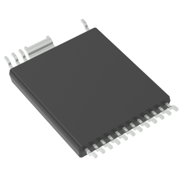


 工商网监
湘ICP备2023018690号
工商网监
湘ICP备2023018690号

