RWM
www.vishay.com
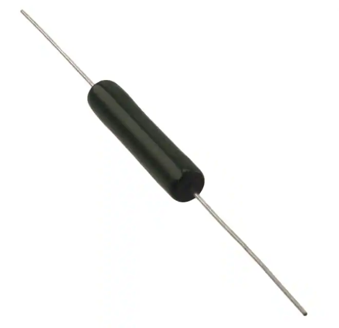
Vishay Sfernice
Enamelled Wirewound Power Resistors Axial Leads
FEATURES
• High dissipation up to 30 W (25 °C)
• Fire proof
• Excellent endurance typical drift ± 1.5 % after
1000 h
• Conformal vitreous enamel
• All welded construction
• Low ohmic values 0.33 Ω available
• Termination: Sn/Ag/Cu
• Material categorization: for definitions of compliance
please see www.vishay.com/doc?99912
As a result of more than 50 years of experience and
continuous improvements the RWM series of resistors
features proven reliability in AC or DC applications.
The performance of this series of professional resistors fully
meets the requirements of the following specifications:
- NF C 83-210-001
- CECC 40201-001
- BS - CECC 40201-002
The high quality of the RWM resides mainly in the use of a
proprietary Vishay Sfernice enamel fired at high temperature
and free from any compound liable to corrode the resistive
wire.
DIMENSIONS in millimeters
25 min.
A
25 min.
ØB
Ø 0.8 ± 0.1
RWM
6 x 34
RWM
8 x 34
RWM
8 x 45
RWM
10 x 45
RWM
10 x 64
RWM
10 x 65
A
33.7 ± 1
33.7 ± 1
45.8 ± 2
45.8 ± 2
63.8 ± 1
63.8 ± 1
ØB
7.4 ± 1.5
7.4 ± 1.5
9.4 ± 1.5
9.4 ± 1.5
9.4 ± 1.5
9.4 ± 1.5
4
4
8
8
14
14
Weight in g
STANDARD ELECTRICAL SPECIFICATIONS
MODEL
SIZE
RESISTANCE
RANGE
Ω
RATED POWER
P25 °C
W
LIMITING ELEMENT
VOLTAGE
V
TOLERANCE
±%
RWM 6 x 34
0634
0.33 to 36K
8
500
1, 2, 5
RWM 8 x 34
0834
0.33 to 36K
11
650
1, 2, 5
RWM 8 x 45
0845
0.47 to 62K
11
650
1, 2, 5
RWM 10 x 45
1045
0.47 to 62K
25
800
1, 2, 5
RWM 10 x 64
1064
0.68 to 100K
25
800
1, 2, 5
RWM 10 x 65
1065
0.68 to 100K
30
800
1, 2, 5
Revison: 20-Oct-2021
Document Number: 50008
1
For technical questions, contact: sferfixedresistors@vishay.com
THIS DOCUMENT IS SUBJECT TO CHANGE WITHOUT NOTICE. THE PRODUCTS DESCRIBED HEREIN AND THIS DOCUMENT
ARE SUBJECT TO SPECIFIC DISCLAIMERS, SET FORTH AT www.vishay.com/doc?91000
�RWM
www.vishay.com
Vishay Sfernice
TECHNICAL SPECIFICATIONS
VISHAY SFERNICE SERIES AND
STYLE
RWM
6 x 34
RWM
8 x 34
RWM
8 x 45
at +70 °C
7W
9.5 W
9.5 W
at +25 °C
8W
11 W
11 W
With Surface Temp.
≤ +450 °C
12 W
14 W
20 W
Ohmic Range in Relation to Tolerance
± 5 % E24 Series
0.33 Ω
36 kΩ
0.33 Ω
36 kΩ
Qualified Ohmic Range
NF C 83-210
0.33 Ω
15 kΩ
-
Limiting Element Voltage
500 V
650 V
650 V
800 V
800 V
800 V
Critical Resistance
31 kΩ
-
38 kΩ
25.6 kΩ
25.6 kΩ
21.3 kΩ
Power Rating
RWM
10 x 45
RWM
10 x 64
RWM
10 x 65
21 W
21 W
25.8 W
25 W
25 W
30 W
25 W
25 W
30 W
0.47 Ω
62 kΩ
0.47 Ω
62 kΩ
0.68 Ω
100 kΩ
0.68 Ω
100 kΩ
0.47 Ω
33 kΩ
-
-
-
PERFORMANCE
CECC 40201 - EN 140-201
TESTS
TYPICAL DRIFTS
CONDITIONS
REQUIREMENTS
Short Time Overload
10 Pr during 10 s
25 °C ambient
± (2 % + 0.1 Ω)
± (0.5 % + 0.05 Ω)
Temperature Cycling
(5 cycles)
-55 °C +200 °C
± (1 % + 0.05 Ω)
± (0.5 % + 0.05 Ω)
56 days
40 °C ambient - R.H. 95 %
± (5 % + 0.1 Ω)
± (0.5 % + 0.05 Ω)
Tensile test: 20 N
2 successive bending
2 full rotations of 180°
± (1 % + 0.05 Ω)
± (0.1 % + 0.05 Ω)
1000 h at Pr
90’/30’ cycle
25 °C ambient
± (5 % + 0.1 Ω)
± (1.5 % + 0.05 Ω)
Humidity (Steady State)
Terminal Strength
Load Life
OVERLOAD
Heavy overloads can be endured in the form of short pulses
< 0.1 s. Particular requirements should be submitted to
Vishay Sfernice, specifying peak voltage, cycle and
environmental conditions.
RECOMMENDATIONS FOR USE
Since these components are high dissipation power
resistors, customers are advised to use a high melting point
solder.
For low ohmic values, the measurement becomes critical
and the connecting wires resistance is to be included. The
value is measured at 5 mm from the resistor body.
Group Mounting
In a still atmosphere, a distance between axes equal to five
times the resistor’s diameter is recommended.
Cabinet Mounting
• Unventilated box: Dissipation should be reduced (see
dimensional drawing).
• Forced ventilation: If conditions are appropriate,
dissipation may be doubled or even trebled.
• In any case: The surface temperature at the hottest point
should not exceed 450 °C.
These aspects should be considered by the end user.
ELECTRICAL SPECIFICATIONS
Tolerance
Temperature Coefficient
Dielectric Withstanding Voltage NF EN140000
Inductance
Revison: 20-Oct-2021
Standard
On request
± 5 % (NI ± 10 %)
± 1 % and ± 2 % (NI ± 5 %)
+75 ppm/°C typical
500 VRMS - 1 min - 10 mA
Non inductive (Ayrton-Perry) winding available
Document Number: 50008
2
For technical questions, contact: sferfixedresistors@vishay.com
THIS DOCUMENT IS SUBJECT TO CHANGE WITHOUT NOTICE. THE PRODUCTS DESCRIBED HEREIN AND THIS DOCUMENT
ARE SUBJECT TO SPECIFIC DISCLAIMERS, SET FORTH AT www.vishay.com/doc?91000
�RWM
www.vishay.com
Vishay Sfernice
POWER RATING
TYPICAL TEMPERATURE RISE
RATED POWER IN %
100
75
50
25
400
45
45 10 x
x
10
64
x
10
65
200
100
0
350
300
200
100
25
8
x
300
0
0
6x
8 34
x
34
HOT SPOT TEMPERATURE IN °C
500
116
0
2
4
6
AMBIENT TEMPERATURE IN °C
8 10 12 14 16 18 20 22 24 26 28 30
RATED POWER IN W
MARKING
Vishay Sfernice trademark, model and style if applicable, ohmic value, resistance tolerance, manufacturing date (year - month).
ORDERING INFORMATION
RWM
6 x 34
MODEL
STYLE
XXX
1U2
±5%
S09
e1
NI OPTIONAL
SPECIAL
DESIGN
OHMIC VALUE
TOLERANCE
PACKAGING
LEAD
(Pb)-FREE
Non inductive
winding
Method N°
optional
Custom items
are subject to
extra charge and
minimum order.
Please see price list.
GLOBAL PART NUMBER INFORMATION
R
W
GLOBAL
MODEL
RWM
M
0
6
3
4
1
R
2
0
J
S
0
9
SIZE
OPTION
OHMIC VALUE
TOLERANCE
PACKAGING
SPECIAL
d x L:
0634
0834
0845
1045
1064
1065
Blank
The first three digits are
significant figures and the
last digit specifies the
number of zeros to follow.
R designates decimal point.
48R7 = 48.7 Ω
1R20 = 1.2 Ω
1002 = 10 000 Ω
R330 = 0.33 Ω
...
F=1%
G=2%
J=5%
K = 10 %
Size 0845, 1045,
1064, 1065:
B25 = box
(50 pieces)
As
applicable.
Ex: AD5
Revison: 20-Oct-2021
or
N
(non inductive
winding)
E
1
LEAD
(Pb)-FREE
Sn(99),
Ag(0.3),
Cu(0.7):
E1
Size 0634, 0834:
S09 = box
(50 pieces)
Document Number: 50008
3
For technical questions, contact: sferfixedresistors@vishay.com
THIS DOCUMENT IS SUBJECT TO CHANGE WITHOUT NOTICE. THE PRODUCTS DESCRIBED HEREIN AND THIS DOCUMENT
ARE SUBJECT TO SPECIFIC DISCLAIMERS, SET FORTH AT www.vishay.com/doc?91000
�Legal Disclaimer Notice
www.vishay.com
Vishay
Disclaimer
ALL PRODUCT, PRODUCT SPECIFICATIONS AND DATA ARE SUBJECT TO CHANGE WITHOUT NOTICE TO IMPROVE
RELIABILITY, FUNCTION OR DESIGN OR OTHERWISE.
Vishay Intertechnology, Inc., its affiliates, agents, and employees, and all persons acting on its or their behalf (collectively,
“Vishay”), disclaim any and all liability for any errors, inaccuracies or incompleteness contained in any datasheet or in any other
disclosure relating to any product.
Vishay makes no warranty, representation or guarantee regarding the suitability of the products for any particular purpose or
the continuing production of any product. To the maximum extent permitted by applicable law, Vishay disclaims (i) any and all
liability arising out of the application or use of any product, (ii) any and all liability, including without limitation special,
consequential or incidental damages, and (iii) any and all implied warranties, including warranties of fitness for particular
purpose, non-infringement and merchantability.
Statements regarding the suitability of products for certain types of applications are based on Vishay's knowledge of typical
requirements that are often placed on Vishay products in generic applications. Such statements are not binding statements
about the suitability of products for a particular application. It is the customer's responsibility to validate that a particular product
with the properties described in the product specification is suitable for use in a particular application. Parameters provided in
datasheets and / or specifications may vary in different applications and performance may vary over time. All operating
parameters, including typical parameters, must be validated for each customer application by the customer's technical experts.
Product specifications do not expand or otherwise modify Vishay's terms and conditions of purchase, including but not limited
to the warranty expressed therein.
Hyperlinks included in this datasheet may direct users to third-party websites. These links are provided as a convenience and
for informational purposes only. Inclusion of these hyperlinks does not constitute an endorsement or an approval by Vishay of
any of the products, services or opinions of the corporation, organization or individual associated with the third-party website.
Vishay disclaims any and all liability and bears no responsibility for the accuracy, legality or content of the third-party website
or for that of subsequent links.
Except as expressly indicated in writing, Vishay products are not designed for use in medical, life-saving, or life-sustaining
applications or for any other application in which the failure of the Vishay product could result in personal injury or death.
Customers using or selling Vishay products not expressly indicated for use in such applications do so at their own risk. Please
contact authorized Vishay personnel to obtain written terms and conditions regarding products designed for such applications.
No license, express or implied, by estoppel or otherwise, to any intellectual property rights is granted by this document or by
any conduct of Vishay. Product names and markings noted herein may be trademarks of their respective owners.
© 2022 VISHAY INTERTECHNOLOGY, INC. ALL RIGHTS RESERVED
Revision: 01-Jan-2022
1
Document Number: 91000
�


 工商网监
湘ICP备2023018690号
工商网监
湘ICP备2023018690号
