Models 117S, 126S, 151S and 176S
Vishay Techno
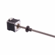
3/8" [9.52mm] Sq. Wirewound Trimmers
FEATURES
• Precious metal wiper. • 1.0 watt to + 85°C. • TCR ± 50PPM/°C. • Solderable leads. • Military quality at affordable prices.
APPLICATIONS
Wirewound trimmers are particularly useful in those applications where any combination of high power, low temperature coefficient of resistance and/or excellent long term life stability are important design considerations.
STANDARD RESISTANCE VALUES
RESISTANCE* (Ohms) 10 20 50 100 200 500 1k 2k 5k 10k 20k 25k 35k 50k *Other resistances available upon request. NOMINAL RESOLUTION (%) 1.10 .85 .65 .51 .40 .45 .34 .27 .20 .16 .13 .12 .11 .10
ELECTRICAL SPECIFICATIONS
Electrical Travel: 22 ± 4 turns. Resistance Range: 10 ohms to 10 kilohms. Extended range available in non MIL-Spec product. Resistance Tolerance: ± 5% standard. Closer tolerances available. Temperature Coefficient: (- 65°C to + 150°C) ± 50PPM/°C. Power Rating: 1.0 watt at + 85°C derated to 0 watt at + 150°C. These specifications exceed MIL-Spec. End Resistance: 1 ohm or 2%, whichever is greater. Equivalent Noise Resistance (ENR): 100 ohms maximum. Dielectric (DWV): 1000 VAC at atmospheric pressure. These specifications exceed MIL-Spec. Insulation Resistance: >100,000 Megohms (500 VDC). These specifications exceed MIL-Spec.
MECHANICAL SPECIFICATIONS
Operating Torque: 5 ounce inch maximum. Rotation: Clutch stop, wiper idles. Weight: 0.935 grams maximum. Resistive Element: Nickel chromium. Rotational Life: 200 cycles minimum. Terminal Strength: 2 pounds for 10 seconds.
CIRCUIT DIAGRAM
1 2 3
ENVIRONMENTAL SPECIFICATIONS
Temperature Limits: - 65°C to + 150°C. Sealing: Fully sealed case (non-hermetic).
CW
DIMENSIONAL CONFIGURATIONS 3/8" [9.52mm] Square [Numbers in brackets indicate millimeters]
L Lead Style - 117S
0.419 ± 0.010 [10.64 ± 0.254] 0.055 ± 0.005 [1.40 ± 0.127] 0.023 ± 0.003 [.584 ± 0.076]
X
P Lead Style - 126S
0.040 ± 0.010 [1.02 ± 0.254] 0.375 ± 0.005 [9.52 ± 0.127]
0.375 ± 0.005 [9.52 ± 0.127] 0.023 ± 0.003 [.584 ± 0.076]
2 1 3
0.075 ± 0.010 [1.90 ± 0.254] Radius
X
0.380 ± 0.005 G Y • • [9.65 ± 0.127] CW • R
0.117 ± 0.005 [2.97 ± 0.127]
0.025 ± 0.003 [0.635 ± 0.076] 0.167 ± 0.005 [4.24 ± 0.127]
0.313 ± 0.005 [7.95 ± 0.127]
0.100 ± 0.005 [2.54 ± 0.127] 0.100 ± 0.005 [2.54 ± 0.127]
0.023 ± 0.003 [.584 ± 0.076]
0.060 ± 0.005 [1.52 ± 0.127] Dia.
0.314 ± 0.005 [7.98 ± 0.127]
0.217 ± 0.005 [5.51 ± 0.127] 0.300 [7.62] Min. 0.027 ± 0.002 [.686 ± 0.051] Dia.
#30 AWG leads, color coded Teflon insulated 6" [152.40mm] minimum length
0.150 ± 0.010 [3.81 ± 0.254]
0.093 ± 0.005 [2.36 ± 0.127] Dia.
www.vishay.com 26
Document Number 68016 Revision 23-Sep-99
�Models 117S, 126S, 151S and 176S
Vishay Techno
DIMENSIONAL CONFIGURATIONS 3/8" [9.52mm] Square [Numbers in brackets indicate millimeters]
W Lead Style - 151S
0.314 ± 0.005 [7.98 ± 0.127] 0.139 ± 0.005 [3.53 ± 0.127] 0.040 ± 0.005 [1.02 ± 0.127] 0.025 ± 0.003 [.635 ± 0.076] 0.190 ± 0.005 [4.83 ± 0.127] 0.093 ± 0.005 [2.36 ± 0.127] Dia. 0.023 ± 0.003 [.584 ± 0.076]
321
X Lead Style - 176S
0.190 ± 0.005 [4.83 ± 0.127] 0.040 ± 0.005 [1.02 ± 0.127] 0.025 ± 0.003 [0.635 ± 0.076] 0.346 ± 0.005 [8.79 ± 0.127] 0.093 ± 0.005 [2.36 ± 0.127] Dia.
321
0.375 ± 0.005 [9.52 ± 0.127]
0.410 ± 0.005 [10.41 ± 0.127]
0.410 ± 0.010 [10.41 ± 0.254]
0.375 ± 0.005 [9.52 ± 0.127]
0.023 ± 0.003 [.584 ± 0.076]
0.300 [7.62] Min. 0.027 ± 0.002 [.686 ± 0.051] Dia. 0.100 ± 0.005 [2.54 ± 0.127]
0.300 [7.62] Min. 0.027 ± 0.002 [.686 ± 0.051] Dia. 0.100 ± 0.005 [2.54 ± 0.127] 0.100 ± 0.005 [2.54 ± .127] 0.139 ± 0.005 [3.53 ± 0.127]
0.100 ± 0.005 [2.54 ± 0.127]
ENVIRONMENTAL PERFORMANCE
TEST1 Power Conditioning Thermal Shock Low Temperature Storage Low Temperature Operation High Temperature Exposure Moisture Resistance Resistance to Soldering Heat Shock Vibration Rotational Life Load Life
1
CONDITIONS (108) (107) 50 hours at 1 watt at + 25°C 5 cycles, -55°C to + 125°C 72 hours, no load at - 65°C 1 hour storage, 45 minutes rated power at - 55°C 1000 hours, no load at + 150°C (106) (210) (213) (204) 480 hours at rated power with humidity ranging from 80% RH to 98% RH + 350°C for 3 seconds 18 shocks, 100g, 6 ms, sawtooth, 3 axes 10 to 2000 Hz, 20g, 12 hours, 3 axes 200 cycles (108) 10,000 hours at rated power at + 85°C
MIL-PRF-39015 REQUIREMENT ∆R ≤ 0.5%2 ∆R ≤ 1.0%2 ∆R ≤ 1.0%
2
TYPICAL CHANGE ∆R < 0.08% ∆R < 0.07% ∆R < 0.05% ∆R < 0.08% ∆R < 0.03% ∆R < 0.22% ∆R < 0.02% ∆R < 0.27% ∆R < 0.04% ∆R < 0.06% ∆R < 0.23%
∆R ≤ 1.0%2,3 ∆R ≤ 1.0%
2,3
∆R ≤ 1.0%2 ∆R ≤ 1.0%2 ∆R ≤ 1.0%2,3 ∆R ≤ 1.0% ∆R ≤ 2.0% ∆R ≤ 3.0%
2,3
Numbers in parenthesis refer to test method MIL-STD-202 as modified by the detail specification. 2 For values below 100 ohms, add 0.05 ohm to the allowable change. 3 The referenced tests also require that setting stability change shall not exceed ± 0.05 percent plus the specified maximum resolution.
DERATING
HOW TO ORDER
1.00 WATTS 0.80 0.60 0.40 0.20 0 25 50 75 85 100 125 150 175 AMBIENT TEMP. DEG. CENTIGRADE
117S MODEL
117S = Teflon Leadwire 126S = PC Mount 151S = Top Adjustment Screw 176S = Side Adjustment Screw
501 VALUE
First two digits are significant figures. Last digit specifies number of zeros to follow.
Document Number 68016 Revision 23-Sep-99
www.vishay.com 27
�


 工商网监
湘ICP备2023018690号
工商网监
湘ICP备2023018690号