DLE45/60 Series
LED Drivers
45/60 Watts
xxx Series
• AC Input LED Driver
• Constant Voltage/Constant Current Operation
• Constant Current Dimming Versions
• High Efficiency
• Water Proof to IP67
• Class 2
• 3 Year Warranty
The DLE series of AC input LED drivers incorporate universal input with active power
factor correction in a two power stage design, eliminating flicker while providing a high
efficiency solution. Designed as a class II isolation product, without the need for a safety
earth, DLE series LED drivers are also approved as a class 2 limited power source,
making them suitable for a wide range of applications. Dimmable constant current
versions are available with the facility for PWM, voltage and resistance programming.
Dimensions:
DLE45/60:
6.73 x 1.78 x 1.27” (164.1 x 45.3 x 32.5 mm)
Models & Ratings - Constant Voltage / Constant Current Models
Output Power
Output Voltage
Output Current
Output Voltage Range in
Constant Current Mode
OVP Range
Efficiency(1)
Model Number
45 W
45 W
48 W
40 W
50 W
60 W
60 W
60 W
60 W
24 V
36 V
48 V
57 V
12 V
24 V
36 V
48 V
57 V
1850 mA
1250 mA
1000 mA
700 mA
4200 mA
2500 mA
1650 mA
1250 mA
1050 mA
16 - 24 V
24 - 36 V
34 - 48 V
40 - 57 V
9 - 12 V
16 - 24 V
24 - 36 V
34 - 48 V
40 - 57 V
26.4-31.2 V
39.6-46.8 V
52.8-62.4 V
62.9-70.0 V
13.2-15.6 V
26.4-31.2 V
39.6-46.8 V
52.8-62.4 V
62.9-70.0 V
85.0%
86.0%
87.0%
87.0%
86.0%
86.0%
87.0%
88.0%
88.0%
DLE45PS24
DLE45PS36
DLE45PS48
DLE45PS57
DLE60PS12
DLE60PS24
DLE60PS36
DLE60PS48
DLE60PS57
Models & Ratings - Dimmable Models
Output Power
Output Voltage
Output Current
Output Voltage Range in
Constant Current Mode
OVP Range
Efficiency(1)
Model Number
45 W
45 W
48 W
40 W
50 W
60 W
60 W
60 W
60 W
24 V
36 V
48 V
57 V
12 V
24 V
36 V
48 V
57 V
1850 mA
1250 mA
1000 mA
700 mA
4200 mA
2500 mA
1650 mA
1250 mA
1050 mA
16 - 24 V
24 - 36 V
34 - 48 V
40 - 57 V
9 - 12 V
16 - 24 V
24 - 36 V
34 - 48 V
40 - 57 V
26.4-31.2 V
39.6-46.8 V
52.8-62.4 V
62.9-70.0 V
13.2-15.6 V
26.4-31.2 V
39.6-46.8 V
52.8-62.4 V
62.9-70.0 V
85.0%
86.0%
87.0%
87.0%
86.0%
86.0%
87.0%
88.0%
88.0%
DLE45PS1850-AD
DLE45PS1250-AD
DLE45PS1000-AD
DLE45PS700-AD
DLE60PS4200-AD
DLE60PS2500-AD
DLE60PS1650-AD
DLE60PS1250-AD
DLE60PS1050-AD
Notes
1. Typical efficiency at full load and 230 VAC input.
1
www.xppower.com
�DLE Series
LED Drivers
Input
Maximum
Units
Notes & Conditions
Input Voltage - Operating
Characteristic
Minimum
90
Typical
305
VAC
See derating curve
Input Frequency
47
63
Hz
Power Factor
Input Current
>0.9
Measured at 230 VAC, full load
0.6
115 VAC
A
0.3
Inrush Current
Input Protection
230 VAC
45
A
Maximum
Units
Notes & Conditions
57
VDC
See models and ratings table
1.5
s
230 VAC cold start, +25 ºC
Internal T1.0 A/250 V fuse fitted in line
Output
Characteristic
Minimum
Output Voltage
12
Typical
Minimum Load
No minimum load required
Start Up Delay
Hold Up Time
20
Measured at 115 VAC
ms
Line Regulation
±0.5
%
±1
Load Regulation
Constant voltage mode
%
±5
Turn On Overshoot
7
%
Constant voltage mode
4
%
Deviation, recovery to within 1% in 10 ms for a 50%
load change
200/250
mV pk-pk
105
%
Transient Response
Ripple & Noise
Constant current mode
≤24 V/>24 V. Measured using 12” twisted pair with 0.1 µF
and 47 µF capacitors in parallel at 20 MHz bandwidth, at 25 °C
Overvoltage Protection
See models and ratings table, recycle AC to Reset
Overload Protection
95
Auto Recovery
Short Circuit Protection
Trip & restart (hiccup mode)
Temperature Coefficient
0.04
%/˚C
Constant Current Curve
Output Voltage
Vo max
Load Regulation in
Constant Current Mode
Vo min
Trip & Restart Zone
0
10
20
30
40
50
60
70
Output Current (%)
80
90
100
General
Characteristic
Minimum
Efficiency
Isolation: Input to Output
Switching Frequency
Mean Time Between Failure
Weight
Typical
Maximum
87
Units
%
3750
Notes & Conditions
See models and tables
VAC
100
kHz
>200
kHrs
0.9 (410)
lb (kg)
www.xppower.com
MIL-HDBK-217F at 25 °C GB
2
�DLE Series
LED Drivers
Environmental
Characteristic
Maximum
Units
Notes & Conditions
Operating Temperature
Minimum
-20
+50
°C
See derating curve
Operating Humidity
20
90
%
RH, non-condensing
+80
°C
Some specification parameters maybe exceeded
until after 20 minutes warm up period.
3000
m
Storage Temperature
Typical
-40
Operating Altitude
Shock
30 g pk, half sine, 6 axes EN60068-2-27, -2-47
& MIL-STD-810F 514.5 cat 4
Vibration
10-500 Hz, 2 g, 10 mins/cycle, 6 cycles in each
of axes
Derating Curves
80
80
Load (%)
100
Load (%)
100
60
40
20
0
-20
60
40
20
-10
0
10
20
30
40
50
60
0
90
70
100
305
Temp (˚C)
Input Voltage (VAC)
EMC: Emissions
Phenomenon
Standard
Test Level
Conducted
EN55015
Class B
Radiated
EN55015
Class B
Harmonic Current
EN61000-3-2
Class C
Voltage Fluctuations
EN61000-3-3
Criteria
Notes & Conditions
Notes & Conditions
EMC: Immunity
Phenomenon
Standard
Test Level
Criteria
Equipment for General Lighting
Purposes
EN61547
as below
as below
ESD Immunity
EN61000-4-2
Radiated Immunity
EN61000-4-3
A
2
8 kV air and 4 kV contact
A
EFT/Burst
EN61000-4-4
2
A
Surges
EN61000-4-5
Installation class 3
A
Conducted
EN61000-4-6
2
A
Magnetic Field
EN61000-4-8
2
A
Dips and Interruptions
EN61000-4-11
Dip: 30%, 10 ms
A
Dip: 30%, 200 ms
A/B
At 230 VAC/100 VAC
Int: 100%, 8.3 ms
A/B
At 230 VAC/100 VAC
Safety Approvals
3
Safety Agency
Safety Standard
UL
UL8750
TUV
EN61347
Notes & Conditions
CE
CE Mark
IEC
IEC61347-2-13 used in conjunction with IEC61347-1
IP
IEC60529
www.xppower.com
�DLE Series
LED Drivers
Mechanical Details - Constant Voltage / Constant Current
6.46 (164.1)
AC N (Blue)
AC L (Brown)
0.13 (3.5)
0.13 (3.5)
1.78
(45.3)
SJTW 18 AWG 2C
0.13
(3.5)
1.27 ±0.7 (150.0 ±20.0)
R1.8
V+ (Red)
UL 2464 18 AWG 2C
0.13 (3.5)
V- (Black)
1.27 ±0.7 (150.0 ±20.0)
6.73 (171.1)
1.27
(32.5)
Mechanical Details - Dimmable Version
6.46 (164.1)
0.13 (3.5)
0.13 (3.5)
SJTW 18AWG 2C
1.78
(45.3)
AC N(Blue)
AC L(Brown)
0.13
(3.5)
1.27 ±0.7 (150.0 ±20.0)
R1.8
UL 2464 18AWG 4C
V+ (Red)
V- (Black)
Dim+ (Blue)
Dim- (White)
1
0.13 (3.5)
1.27 ±0.7 (150.0 ±20.0)
6.73 (171.1)
1.27
(32.5)
Notes
1. Dimensions shown in inches (mm).
2. Weight: 2.8 lb (1.27 kg).
3.Tolerance: 0.X = ±0.008 (±0.2)
0.XX = ±0.002 (±0.05)
www.xppower.com
4
�DLE Series
LED Drivers
Output Current Adjustment by Variable Resistor
V+
Dim+
Connect a variable resistor between Dim+ and Dim-.
DLE
V-
Dim-
1
The Dimmed output current can be determined using the equation:
Dimmed Current =
Maximum Current x R
100 k
Where the value of R is between 10 kΩ and 100 kΩ. The corresponding
range of output current is 10% to 100%
D
1
1
Output Current Adjustment by DC Voltage
1
D
Connect a variable voltage betwen Dim+ and Dim-
D
V+
1
Dim+
+
DLE
1V-
Dim-
Maximum Current x D P
D
The dimmed output current is given by:
Dimmed Current =
1
Maximum Current
xV
10 k
Where V is the value of control voltage in the range of 1.0 V to 10.0 VDC.
The corresponding range of output current is 10% to 100%.
1
1
Output Current Adjustment by PWM
=
A Pulse Width Modulated (PWM) signal with duty cycle
DPWM can be applied between Dim+ and Dim-.
10 V
0V
PWM
D
Dim+
Dim-
V+
DLE
V-
D
1
GND
Dimmed Current = Maximum Current x D Pwm % (Dpwm = PWM duty cycle)
The dimmed output current is given by:
Where Dpwm is the % of duty cycle between 10% and 100%. The
corresponding range of output current is 10% to 100%. PWM frequency
should be in the range 0.5 kHz to 5 kHz
D
5
www.xppower.com
25 July 17
�
很抱歉,暂时无法提供与“DLE45PS57”相匹配的价格&库存,您可以联系我们找货
免费人工找货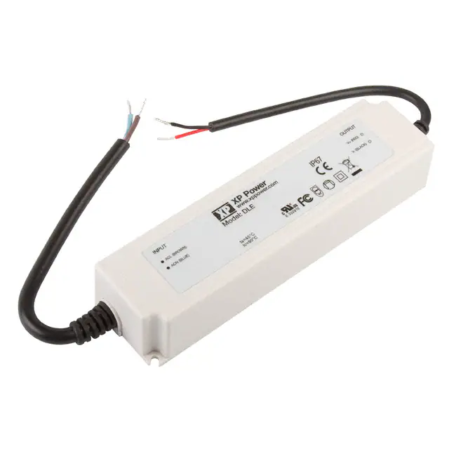


 工商网监
湘ICP备2023018690号
工商网监
湘ICP备2023018690号
