承
认
书
APPROVAL SHEET
客 户 名 称:
深圳市福昌辉科技有限公司
Customer
绕线型片式电感器
产 品 名 称:
Wire Wound Chip inductor
Part Name
产 品 规 格:
FHW1008UC1R0KGT
Specification
版 本 号:
16.01
Version No.
日
期:
2017-7-20
DATE
制造
客户
Manufacturer
Customer
拟制
审核
确认
检验
审核
批准
Draft by
Checked by
Approve by
Check by
Checked by
Approval by
林晓华
徐雪枫
区军沛
�序号
No
目
录
TABLE OF CONTENTS
1
履 历 表 Resume
2
外形尺寸与内部结构 Dimension & Inner-configuration
3
产品品名构成 Product Spec. Model
4
电性能参数表 Electrical Characteristics List
5
可靠性试验项目 Reliability Testing Items
6
产品包装 Packaging
7
推荐焊接条件 Recommend Soldering Conditions
8
清洗 Cleaning
9
存储要求 Storage Requirements
10
ODS(消耗臭氧层物质)的使用情况 Usage Of ODS
11
注意事项 Notes
Page 1 of 12
�1. 履 历 表 Resume
版本
Version No.
16.01
修 改 明 细
Modify Details
首次发行 Initial issue
日期
Date
2016-04-01
Page 2 of 12
�2
外形尺寸与内部结构 Dimension & Inner-configuration:
序号 No.
1
2
部位 Component
材料 Material
陶瓷芯电感Ceramic Core:陶瓷体Al2O3
瓷/磁芯Core
铁氧体芯电感Ferrite Core:镍锌铁氧体Ni-Zn ferrite
电极Electrode
分类
底层
中层
表层
Type
Layout 0
Layout 1
Layout 2
陶瓷芯电感
钨或钼锰
镍
金或锡
Ceramic core
W or Mo-Mn
Ni
Au or Sn
铁氧体芯电感
银
镍
锡
Ferrite core
Ag
Ni
Sn
3
漆包线wire
铜Cu
4
包封层encapsulation layer
树脂Epoxy
5
标识Marking
树脂Epoxy
单位Unit:mm(inch)
型号
Size
L (Max)
W (Max)
T (Max)
A
B
C
D
E
2520(1008)
2.92(0.115)
2.79(0.110)
2.10(0.083)
2.00(0.079)
0.50(0.020)
2.54(0.100)
1.02(0.040)
1.27(0.050)
3 产品品名构成 Product Spec. Model
① 绕线型片式电感器系列 Wire Wound Inductor Series;
② 外形尺寸 Dimensions:1008;
③ 芯片类型 Material:UC;
④ 标称电感量 Inductance: 1R0=1000nH;
⑤ 标称电感值偏差 Tolerance:F---±1%;G---±2%;J---±5%;K---±10%;
⑥ 电极表面镀层材料 Terminal:G---金端头 Gold;
⑦ 包装类型 Packaging type:T---卷带盘装 Tape&Reel;B---散装 Bulk。
Page 3 of 12
�4
电性能参数表 Electrical Characteristics List
型号规格
Part NO.
客户料号
Customer
P/N
误差
范围
Tolerance
(%)
标称
感量
Inducta
nce
(nH)
感量测试
频率
Ls Test
frequency
(MHz)
FHW1008UC1R0KGT
/
±10
1000
25
Q值
( Min)
Page 4 of 12
35
Q 值测试
频率
Test
frequency
(MHz)
直流
电阻
Rdc
(Ω)max
50
1.75
测试
自谐振
电压
频率
Test
SRF
voltag
(MHz)min
e(mV)
500
210
额定电流
Idc
(mA)max
370
�5 可靠性试验项目 Reliability Testing Items
序号
No.
项目
Items
1
工作温度范围
Operating
Temperature
Range
2
可焊性
Solder ability
要求
Requirements
试验方法及备注
Test Methods and Remarks
FHW-UC/HC series:-40℃~+125℃
FHW-UF/IF/QF/HF series:-40℃~+85℃
外观不发生变化;超过 90%的焊锡覆盖在
在
端电极表面
(96.5Sn/3.0Ag/0.5Cu)中浸置 5±1
There shall be no case deformation or
秒钟。
change in appearance. The metalized
Dip pads in flux and dip in solder
area must have more than 90% solder
pot(96.5Sn/3.0Ag/0.5Cu)at 245±5℃
coverage.
for 5±1 seconds.
外观不发生变化;感量变化不超过±5%; 在
耐焊接热
3
Soldering Heat
Resistance
介质耐压
Dielectric
4
Withstand
Voltage
绝缘电阻
5
Insulation
Resistance
端电极附着力
(推力测试)
6
Component
Adhesion
(Push of test)
245±5℃
260±5℃
熔
熔
融
融
的
的
焊
焊
锡
锡
Q 值变化不超过±10%。
(96.5Sn/3.0Ag/0.5Cu)中浸置 10±1
There shall be no case deformation or
秒钟。
change
Inductance
Dip pads in flux and dip in solder
shall not change more than ±5%; Q
pot(96.5Sn/3.0Ag/0.5Cu)at 260±5℃
shall not change more than±10%.
for 10±1 seconds.
in
appearance.
外观不发生变化;无击穿现象
here shall be no case deformation or
change in appearance.No evidence of
voltage breakdown.
在电感器端子和包封层间施加 500V 交
流电压,持续一分钟。
Input 500v AC between the electrodes
and the resin of inductor and keep
on one
minute.
在电感器端子和包封层间施加 100V 直
铁氧体芯: ≥500MΩ
流电压,持续一分钟。
陶瓷芯:≥1000 MΩ
Input 100v DC between the electrodes
Ferrite: ≥500MΩ
and the resin of inductor and keep
Ceramic: ≥1000 MΩ
on one
绕线型片式电感器:
Wire Wound Chip inductor:
0402UC series:≥0.45Kg
0603UF series:≥0.9Kg
0603UC series、0805UF series:≥1.3 Kg
Other series: ≥2Kg
Page 5 of 12
minute.
�序号
No.
项目
Items
要求
Requirements
试验方法及备注
Test Methods and Remarks
将规定额定电流 2 倍的直流电流加于电
7
过载
Over Loading
外观不发生变化;电感器不开路.
感器,其电流误差为±2%,,保持 5 分
There shall be no case deformation or
钟。
change in appearance.
Direct current of rating current
Inductors shall not have a open
between inductor terminals , Direct
winding.
current error ±2%, and
keep on
five minutes.
无开路或短路;
感量变化不超过±5%;
Q 值变化不超过±10%。
8
振
动
Vibration
Inductors shall not have a shorted or
open winding.
Inductance shall not change more than
±5%.
振幅 1.5mm,频率 10~55Hz,每个方向
保持 2 小时。
Inductors shall be subjected to
vibration
of
1.5mm
amplitude
frequency 10~55Hz (10Hz to 55Hz to
10Hz in a period of 1 minute) for 2
hours in each of three(X、Y、Z) axes.
Q shall not change more than±10%.
温度变化
9
Temperature
Change
外观不发生变化;
FHW-UC/HC 系列: +125℃ 60 分钟 ←
感量变化不超过±5%;
→ -40℃ 60 分,钟循环 5 次;
Q 值变化不超过±10%
FHW-UF/IF/QF/HF 系列:+85℃ 60 分钟
There shall be no case deformation or
←→ -40℃ 60 分,钟循环 5 次;
change in appearance.
室温下放置一小时后测试。
Inductance shall not change more than
±5%.
Q shall not change more than±10%.
FHW-UC/HC series :+125℃ 60minutes
←→ -40℃ 60minutes 5 Cycles;
FHW-UF/IF/QF/HF
series : +85℃
60minutes ←→ -40℃ 60minutes 5
Cycles;
Inductors are to be tested after 1
hour at room temperature.
10
高温
High
temperature
外观不发生变化;
FHW-UC/HC 系列产品放置于温度+125
感量变化不超过±5%;
±5℃的环境中存放 96±2 小时;
Q 值变化不超过±10%
FHW-UF/IF/QF/HF 系列产品放置于温度
There shall be no case deformation or
+85±5℃的环境中存放 96±2 小时;
change in appearance.
在室温下放置 1 小时后进行测试。
Inductance shall not change more than
±5%.
Q shall not change more than ±10%.
FHW-UC/HC series shall be subjected
to +125±5℃ for 96±2 hours;
FHW-UF/IF/QF/HF series shall be
subjected to +85±5℃ for 96±2
hours;
Inductors are to be tested after one
hour at room temperature.
Page 6 of 12
�序号
No.
项目
Items
要求
Requirements
外观不发生变化;
感量变化不超过±5%;
低温
11
Low
temperature
Q 值变化不超过±10%
There shall be no case deformation or
change in appearance.
Inductance shall not change more than
±5%.
Q shall not change more than±10%
12
恒定湿热
Static Humidity
试验方法及备注
Test Methods and Remarks
将电感器放置于温度-40±2℃的环境
中存放 96±2 小时,然后在室温下放置
1 小时后进行测试。
Inductors shall be subjected to
-40±2℃for 96±2 hours.
Inductors are to be tested after one
hour at room temperature.
外观不发生变化;
将电感器放置在于湿度 93±3%,温度 50
感量变化不超过±5%;
±2℃的环境中存放 96±2 小时,经过 1
Q 值变化不超过±10%
小时的风干后进行测试。
There shall be no case deformation or
Inductors shall be subjected to
change in appearance.
93±3% R.H. at 50±2℃ for 96 ± 2
Inductance shall not change more than
hours .Inductors are to be tested
±5%.
after having air dried for one hou.
Q shall not change more than±10%.
FHW-UC/HC 系列产品加额定电流在 125
±2℃温度条件下存放 1000 小时;
FHW-UF/IF/QF/HF 系列产品加额定电流
在 85±2℃温度条件下存放 1000 小时;
然后在室温下放置 4 小时后进行测试。
FHW-UC/HC series shall be store at
13
耐久性
durability
(Life)
电感器不应短路或断路。
125±2℃ for 1000 hours with rated
Inductors shall not have a shorted or
current applied;
open winding.
FHW-UF/IF/QF/HF series shall be
store at 85±2℃ for 1000 hours with
rated current applied;
Inductors shall be tested after four
hours at room temperature.
Page 7 of 12
�6 产品包装 Packaging
1)编带图 Taping drawings
2)卷盘尺寸 Reel dimensions (Unit:mm)
Part NO.
ΦA
typ.
ΦB
typ.
ΦC
typ.
D typ.
1008
178
60
13
8.4
3) 导带及空格部分 Leader and blank portion
4)编带尺寸 Taping dimensions (Unit: mm)
z 塑料胶带 Embossed tape
Page 8 of 12
�Part NO.
0603
0805
1008
1210
1812
W
E
F
D0
D1
P0
P1
P2
P0×10
t
A0
B0
K0
8.00
1.75
3.50
1.50
0.50
4.00
4.00
2.00
40.00
0.23
1.15
1.85
0.95
8.00
1.75
3.50
1.50
0.65
4.00
4.00
2.00
40.00
0.23
1.85
2.45
1.50
8.00
1.75
3.50
1.50
0.65
4.00
4.00
2.00
40.00
0.25
2.73
2.90
2.34
8.00
1.75
3.50
1.50
0.65
4.00
4.00
2.00
40.00
0.23
2.96
3.60
2.40
12.00
1.75
5.50
1.50
1.50
4.00
8.00
2.00
40.00
0.25
3.22
4.82
2.98
5)剥离力检验
Peeling off force
①盖带的剥离力要求 Peeling required
0402~1210 系列 :20 克~80 克 0402~1210 series :20g~80g
②测试条件 Test condition
盖带剥离速度:300mm/min±10%
Speed of peeling off : 300mm/min±10%
盖带剥离角度:165°~180°
Angle of peeling off: 165°~180°
6)包装数量(单位:粒)Packaging number (Unit: Pcs )
类型 Size
1812
1210
1008
0805
0603
0402
每卷数量 Per Reel
2000
2000
2000
3000
4000
5000
3 卷盒
------
6000
6000
9000
12000
15000
5 卷盒
10000
10000
10000
15000
20000
25000
10 卷盒
------
20000
20000
30000
40000
50000
1.5 盒箱
------
30000
30000
45000
60000
75000
3 盒箱
------
60000
60000
90000
120000
150000
4 盒箱
------
80000
80000
120000
160000
200000
5 盒箱
------
120000
120000
180000
240000
300000
大 3 盒箱
30000
------
------
------
------
------
每盒数量
Per Box
每箱数量
Per Case
Page 9 of 12
�6) 标签粘贴位置 Label stick station
卷盘标签
纸盒标签
纸盒标签
外箱标签
7 推荐焊接条件 Recommend Soldering Conditions
1) 焊接条件 Soldering Conditions
本产品建议使用回流焊接法。
Applicable soldering process to the products is reflow soldering.
① 焊剂要求 Flux, Solder
z
使用松香基助焊剂,禁止使用卤化物含量超过 0.2(wt)%的强酸性助焊剂。
Don’t use highly acidic flux with halide content exceeding 0.2(wt)%(chlorine conversion value).
z
使用无铅焊料(96.5Sn /3.0Ag/0.5Cu)。
Using lead-free solder (96.5Sn /3.0Ag/0.5Cu)。
② 焊接要求 Soldering conditions
z
预热时,产品表温与焊料温度的温差最大不允许超出 150℃,焊接完冷却时,产品表温与溶剂温度
之间的温差最大不超过 100℃。预热不足有可能引发产品表面裂纹,从而导致产品品质下降。
Pre-heating should be in such a way that the temperature difference between solder and ferrite
surface is limited to 150℃ max. Also cooling into solvent after soldering should be in such way
that the temperature difference is limited to 100℃ max. Un-enough pre-heating may cause cracks
on the ferrite, resulting in the deterioration of product quality.
z
产品要在以下画出的曲线允许的范围内进行焊接。其它焊接条件可能引起产品电极的腐蚀。当焊接
重复时,允许的时间为第一次做的累计时间。
Products should be soldered within the following allowable range indicated by the slanted line.
The excessive soldering conditions may cause the corrosion of the electrode. When soldering is
repeated, allowable time is the accumulated time.
2) 回流焊曲线 Reflow soldering profile
Page 10 of 12
�3) 手工焊接 Iron soldering
烙铁温度:350℃ (Max)
功率:最大为 30W
烙铁停留时间:
很抱歉,暂时无法提供与“FHW1008UC1R0KGT”相匹配的价格&库存,您可以联系我们找货
免费人工找货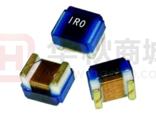


 工商网监
湘ICP备2023018690号
工商网监
湘ICP备2023018690号
