湖南艾华集团股份有限公司
HUNAN AIHUA GROUP CO., LTD
Tel: (0737)6184466
Fax : (0737)6180493
Http://www.aihuaglobal.com
SPECIFICATION
Description: Aluminum Electrolytic Capacitors
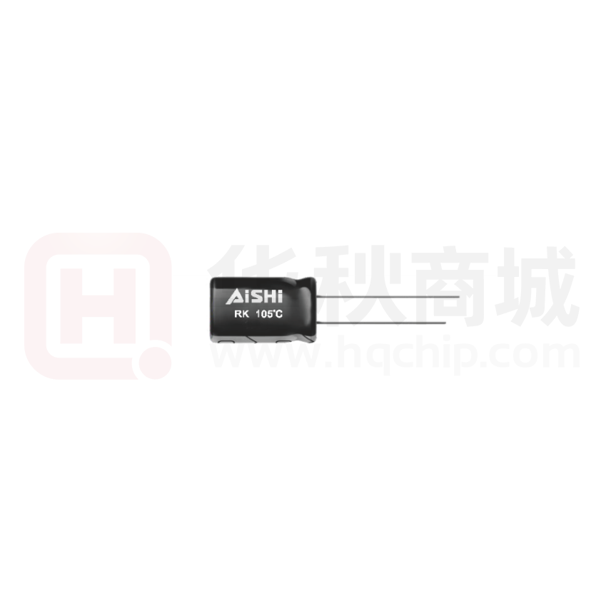
AISHI P/N: ERK2G9220F16OT
SERIES: RK
ITEM: 400V22μF (Φ8×16)
Customer P/N:
No.: CRS-JG-1707313
APPROVED BY
Please Return One Copy with Your Approval
承认后请寄回一份
PREPARED BY
CHECKED BY APPROVED BY
�Starts
File
Released
Description
Approval
Component
Sheet-RK
No./rev
CRS-2010-RK/ 01
变更记录
版本
更改原因
CRS-JG-1707313
Name
File No.
更改内容
生效日期
2017-7-31
新建
新建
Approval
RK
STANDARD
Sheet-RK
Version
MANUAL
01
Page
2
�Customer
RK
SERIES
2017-07-31
DATE
PET
¢d±0.05
F±0.5
L+ α MAX
D+0.5 MAX
4MIN
15 MIN
FIG-1
TABLE-1
No.
1
Customer
Part No.
Aishi
Part No.
ERK2G9220F16OT
Leakage
Tolerance
tanδ
Operating
Surge
Rated
Current
on Rated
Capacitance
Voltage Voltage Temp. Range (120Hz)
(uA)
Capacitance
(μF)
(Max)
(℃)
(Vdc)
(Vdc)
(2min.)
(%)
22
-40~0
400
450
-40~+105
0.15
186
Max Ripple
Current
Endurance
(mArms)
at 105℃
at105℃
(Hours)
Dimensions (mm)
DΦ L
α
d
F
F1
Appearance
Drawing No.
100kHz
200
2000
8
16
2
0.6 3.5
/
FIG-1
�Starts
File
Released
Description
Approval
Component
Sheet-RK
No./rev
CRS-2010-RK/ 01
1 概述 SCOPE
本承认书规定了 RK 系列径向引线引出铝电解电容器的技术规范,本技术规范条文解释权归
本公司所有。
This specification covers “RK series” miniature single-ended aluminum electrolytic capacitors,Aishi
reserves the right of final interpretation for this technical specification.
2 参考标准 APPLICABLE SPECIFICATION
本承认书参考 JIS-C-5101-1 和 JIS-C-5101-4 制定。
This approval sheet consulted the institute of JIS-C-5101-1 and JIS-C-5101-4.
3 工作温度范围 OPERATING TEMPERATURE RANGE
工作温度范围是电容器在施加额定工作电压条件下,可以长期可靠工作的环境温度范围。
-40℃~+105℃(400V.DC)
-25℃~+105℃(450-500V.DC)
Operating temperature range is the range of ambient temperature at which the capacitor can be
operated continuously at rated voltage.
-40℃~+105℃(400V.DC)
-25℃~+105℃(450-500V.DC)
4 测试环境 CONDITION OF TEST
如果没有其他规定,标准的测试、检验环境条件如下所示:
环境温度:15℃~35℃
相对湿度:45%~75%
大气压力:86kPa~106kPa
如果对测试结果有异议,可以在以下条件测试:
环境温度:20±1℃
相对湿度:60%~67%
大气压力:86kPa~106kPa
Unless otherwise specified, the standard range of atmospheric conditions for making
measurements and tests are as follows
Ambient temperature :15℃ to 35℃
Relative humidity :45% to 75%
Air pressure
:86kPa to 106kPa
If there may be doubt on the results, measurements shall be made within the following limits
Ambient temperature :20±1℃
Relative humidity
:60% to 67%
Air pressure
:86kPa to 106kPa
Name
File No.
Approval
RK
STANDARD
Sheet-RK
Version
MANUAL
01
Page
1
�Starts
File
Released
Description
Approval
Component
Sheet-RK
No./rev
CRS-2010-RK/ 01
5 产品特性 PRODUCT CHARACTERISTICS
5.1 电气特性 ELECTRICAL CHARACTERISTICS
序号
项目
测试方法
性能
No.
Item
Test method
Performance
5.1.1
额定工作电压
电压:直流电压值+交流电压峰值≤额定电压
Rated voltage
. Voltage:DC. Voltage + peak ripple voltage ≤
400V.DC~500V.DC
Rated voltage
5.1.2
电容量
Capacitance
测试频率:120Hz(±20%)
容量偏差:-40%~0%
测试电路:串联等效
Capacitance tolerance:
测试电压:0.5Vrms 以下+1.5~ 2.0VDC
-40%~0%
Measuring frequency: 120Hz±20%
Measuring circuit:
Series equivalent circuit
Measuring voltage:
0.5Vrms or less +1.5 to 2.0 VDC
5.1.3
测试条件与 5.1.2 电容量测试相同
DF 不大于规定值
Testing condition are the same as 5.1.2 for
DF: Not more than the specified
capacitance
value.
漏电流
在电容器两端施加额定工作电压,并串联 1000
Leakage current
±100Ω电阻,在施加规定时间电压后,测量漏
400V~450V:
I≤0.02CV+10μA,
500V:
I≤0.03CV+10μA,
(2 分钟后)
400V~450V:
I≤0.02CV+ 10μA
500V:
I≤0.03CV+10μA,
(after 2 min)
损失角正切值
Dissipation Factor
5.1.4
电流。
测试电路如下图:
The rated voltage shall be applied across the
capacitor and its protective resistor which shall be
1000±100Ω. The leakage current shall then be
measured after an electrification period of
schedule time.
I:漏电流(μA)
C:容量(μF)
V:额定工作电压(V)
I:Leakage current(μA)
C:Capacitance(μF)
V:Rated voltage (V)
Rs: Protective resistor(1000±100Ω)
DC ammeter
DC voltmeter
S1: Switch
S2: Protective switch for an ammeter
Name
File No.
Approval
RK
STANDARD
Sheet-RK
Version
MANUAL
01
Page
2
�Starts
File
Released
5.1.5
温度特性
Temperature
Characteristic
5.1.6
Description
Approval
阶段
1
2
3
4
温度
20±2℃
+0
-25, -40 -3 ℃
20±2℃
+3
105 -0 ℃
时间
-2h
15min.
2h
耐浪涌电压
阶段 1:测量容量和阻抗(|z| 20℃ 120Hz±
20%)
阶段 2:电容器恒温贮存 2 小时,在热平衡状态
测阻抗(|z|-25,-40℃ 120Hz±20%)
阶段 4:电容器恒温贮存 2 小时,在热平衡状态
测电容量
Step 1:Capacitance and impedance shall be
measured. (|z| 20℃ 120Hz±20%)
Step 2:After the capacitor being stored for 2 hours,
impedance shall be measured at thermal
stability. (|z|-25,-40℃ 120Hz±20%)
Step 4:After the capacitor being stored for 105℃2
hours, capacitance shall be measured. The
measurement shall be made at thermal stability
施加表 1 所列浪涌电压,充电 30±5 秒,放电
Surge Test
5.5±0.5 分钟作为一个周期,共进行 1000 次。
测试温度:15℃-35℃
然后在标准大气条件下放置达到热稳定,测试各
参数
Application of DC surge Voltage stated at table-1,
1000
times of charging for 30 ± 5 sec.,
discharging with a period of
Component
Sheet-RK
5.5±0.5 min..
Test temperature: 15℃-35℃
No./rev
CRS-2010-RK/ 01
阶段 2:
阻抗值与阶段 1 阻抗值相比,不大
于表 2 要求。
阶段 4:
容量变化应在初值的±20%范围内
Step 2:
Impedance value ratio to the value at
step 1 shall be not more than the
value given table-2
Step 4:
Variation of capacitance Within
±20% of the initial value.
容量变化:在初始值的±20%以内。
损耗角正切值不大于规定值的
200%。
漏电流:达到 5.1.4 要求
Capacitance change:
Within ± 20% of the initial value
Dissipation factor:
Not more than 200% of the
specified value.
Leakage current:
To satisfy No.5.1.4
And the capacitor shall be stored under standard
atmospheric conditions to obtain thermal stability,
after which measurements shall be made.
Test circuit
K
R
+
DC Power
R
Cx
_
Note: This requirement is applicable only to instantaneous over voltage which may
be applied to terminals of capacitor, therefore, not applicable to such
over voltages as often applied.
Name
File No.
Approval
RK
STANDARD
Sheet-RK
Version
MANUAL
01
Page
3
�Starts
File
Released
Description
Approval
5.2 机械特性 MECHANICAL
Component
Sheet-RK
No./rev
CRS-2010-RK/ 01
PERFORMANCE
序号
项目
测试方法
特性
No.
Item
Test method
Performance
5.2.1
端子强度
端子抗拉强度:
Terminal
沿电容器端子引线方向施加拉力(如下表),10±1 秒。 或短路,无可见机械损伤
引线直径Φ 0.45
0.5
0.6
0.8
1.0
When the capacitor is measured,
拉力 N
5
10
20
there shall be no intermittent
端子抗弯强度:
contacts,
or
open
or
在电容器引线施加固定重力(如下表),然后,将电容
short-circuiting.
体弯折 90°后回到原位,再向相反方向弯折 90°后回
There shall be no such mechanical
到原位。
damage.
上述过程在 5 秒内完成。
Strength
测量电容器应无接触不良、开路
0.5
0.6
0.8
1.0
引线直径Φ 0.45
2.5
5
10
拉力 N
Tensile strength of termination:
A static load (stated in the table below) shall be applied
to the terminal in the axial direction and acting in a
direction away from the body for 10±1 sec..
Bending strength of termination:
Hang the specified dead weight (stated in the table
below), then bent the body through 90°, return to the
original position.
Next bent it in opposite direction through 90°with the
same speed, again return to the original position.
Carry out this operation in about 5 sec.
5.2.2
振动试验
Resistance to
Vibration
5.2.3
可焊性
Solderability
Name
File No.
依据 JIS C 5101-1 4.17 试验。
在 3 个互相垂直的方向分别施加 2 小时振动,共 6 小
时
频率:10-55Hz
振幅:1.5mm.
振速:1 分钟内振速 10~55~10Hz
To comply with JIS C 5101-1 4.17
Direction and duration of vibration:
3 orthogonal directions mutually each for 2h , Total 6h.
Vibration Frequency Range :10-55Hz
Peak to peak amplitude: 1.5mm
Sweep rate :10to55to10Hz in about 1 min.
测量电容器应无接触不良开路或
短路,无可见机械损伤。
When the capacitor is measured
there shall be no intermittent
contacts, or open or short circuiting
There shall be no such mechanical
damage.
依据 JISC 5101-1 4.15 进行试验
焊锡温度:235±5℃
浸入时间:2±0.5 秒
To comply with JISC 5101-1 4.15
Temperature of solder: 235±5℃
Dipping time: 2±0.5sec.
This specification shall be met after the capacitors are
stored under standard atmospheric conditions for 6
months.
浸入焊锡的引线表面积约 90%以
上应附着新锡
At least 90% of circumferential
surface of the dipping portion of
termination shall be covered with
new solder.
Approval
RK
STANDARD
Sheet-RK
Version
MANUAL
01
Page
4
�Starts
File
Released
5.3 耐久性测试 ENDURANCE
序号
No.
5.3.1
5.3.2
项目
Item
耐焊接热
Resistance to
soldering heat
稳态湿热
Resistance to damp
heat
(steady state)
5.3.3
Description
Approval
No./rev
CRS-2010-RK/ 01
PERFORMANCE
测试方法
Test method
特性
Performance
容量变化:在初始值±10%范围内
焊槽法:
损失角正切值:不大于规定值
焊锡温度:260±5℃
漏电流:满足 5.1.4 要求
浸入时间:10±1 秒
外观:无异状
电路板 :1.6mm
Variation of capacitance:
Solder bath method
Within ±10% of the initial value
Solder bath temperature : 260±5℃
Dissipation factor:
Immersion time
: 10±1sec.
Not more than the specified value
Printed wiring board: 1.6mm
Leakage current:
To satisfy No.5.1.4
Appearance:
No remarkable abnormality.
容量变化:在初始值±10%范围内
依据 JIS C 5101-1 4.22 进行试验
损失角正切值:不大于规定值
试验温度:40±2℃
漏电流:满足 5.1.4 要求
试验时间:240±8h
外观:无异状
相对湿度:90~95%
试验后,电容器在标准大气条件下 1~2 小时, Variation of capacitance:
Within ±10% of the initial value.
然后测试参数
Dissipation factor:
To comply with JIS C 5101-1 4.22
Not more than the specified value
Test temperature : 40±2℃
Leakage current: To satisfy No.5.1.4
Test time
: 240±8h
Appearance:
Relative humidity: 90~95%
After completion of test, the capacitor shall be No remarkable abnormality.
subjected to standard atmospheric conditions for
1 to 2 hours, after which measurements shall be
made.
高温负荷试验
1. 试验温度:105±2℃,施加额定电压和额定
Load Life Test
纹波电流
Application of the rated voltage and the rated
ripple current, Test temperature:105±2℃
+72
试验时间:2000 -0 h
Test time:
Name
File No.
Component
Sheet-RK
+72
2000 -0 h
Approval
RK
STANDARD
Sheet-RK
Version
MANUAL
容量变化:在初始值±20%范围内
损耗角正切值:不超过规定值的 200%
漏电流:不大于规定值
外观:无异状
Variation of capacitance:
Within ±20% of the initial value.
Dissipation factor:
Not more than 200% of the specified
value
Leakage current:
Not more than the specified value
Appearance:
No remarkable abnormality.
01
Page
5
�Starts
File
Released
5.3.4
Description
Approval
高温贮存试验
+48
在 105±2℃环境下无负荷贮存 1000 -0 h,至
Shelf Life Test
少恢复 16 小时后。
The capacitors are then stored with no voltage
applied at a temperature of 105 ± 2 ℃ for
+48
1000 -0 h
5.3.5
and then resumed 16 hours.
在电容器两极施加反向直流电压,其中通过的
电流为 5 A,在测试时防爆装置应能在 30 分
钟内动作。
D.C.Application test
The capacitor shall be subjected to a reverse
D.C. voltage.
The current flowing through the capacitor shall
be 5A. If the vent does operate with the voltage
applied for 30 minutes, the test is considered to
be passed.
防爆试验
Safety Vent
Component
Sheet-RK
No./rev
CRS-2010-RK/ 01
容量变化:初始值±20%范围内。
损耗角正切值:不超过规定值的 200%
漏电流:不超过规定值的 200%
外观:无异状
Variation of capacitance:
Within ±20% of the value before test.
Dissipation factor:
Not more than 200% of the specified
value
Leakage current:
Not more than 200% of the specified
value
Appearance:
No remarkable abnormality.
上述过程中应无引线、铝箔等散射,
无火花产生。
The vent device is actuated under the
test conditions, thereby preventing
terminals, metal pieces, etc, of the
capacitor from scattering due to burst,
the case from separating from the seal
packing, or the capacitor from
producing flame.
※ 表 2(TABLE 2)
阻抗比
Max. Impedance
Ratio
Name
File No.
额定工作电压
400
450
500
|z|-25℃/|z|20℃
3
5
6
|z|-40℃/|z|20℃
6
-
-
Rated voltage (v)
Approval
RK
STANDARD
Sheet-RK
Version
MANUAL
01
Page
6
�Starts
File
Released
Description
Approval
Component
Sheet-RK
No./rev
CRS-2010-RK/ 01
6 标记 MARKING
6.1 在电容器体上应注明如下内容:
(1)生产厂商商标
RK 105℃
YyWw□PET (Yy 表示年份,Ww 表示制造周期,
(2)型号-额定温度
(3)周期代码-我司代码-套管材质
□表示我司代码,我司代码:
“Z、Y、J、S……”
PET 表示套管材质)
--V--μF
(4)电压容量
(5)负极标志
6.1The following items shall be marked indelibly on the capacitor.
(1)Manufacture’s name or trade mark.
(2)Model - Rated temperature
RK 105℃
(3)Cycle code-AIHUA code -Sleeve material
YyWw□ PET (Yy denotes last two digit of years and Ww
denotes the week in which the capacitor is
Manufactured,□denotes the code of AIHUA,AIHUA code:
” Z、Y、J、S……”PET denotes the sleeve material )
(4)Voltage Capacity
(5)Polarity of the terminals
--V--μF
6.2 标记颜色 Marking color
套管颜色:黑色
标记颜色:白
Sleeve color:Black
Marking color:White
7 纹波电流频率因子 RIPPLE CURRENT FREQUENCY COEFFICIENT
Freq. (Hz)
WV(Vdc)
400~500
Name
File No.
120
1k
10k
100k
0.50
0.80
0.90
1.00
Approval
RK
STANDARD
Sheet-RK
Version
MANUAL
01
Page
7
�Starts
File
Released
Description
Approval
Component
Sheet-RK
No./rev
CRS-2010-RK/ 01
8 物料编码 PART NO SYSTEM
1
2
3
4
5
6
7
8
9
10 11 12
13 14 15
16
Sleeve
Terminal
Size
Capacitance
Capacitance tolerance
Voltage
code⑧
code⑦
code⑥
code⑤
code④
code③
Series code②
Category code①
①Category
④Capacitance Tolerance
③Voltage code
Type
Code
WV(V)
1th
4
6.3
10
16
25
35
40
50
63
80
100
160
180
200
220
250
315
350
380
400
420
450
500
Electrolytic Capacitor
E
②Series code
Series name
Code
2 th
3 th
WH
W
H
RK
R
K
⑥Size code
ΦD
Code
10th
4
5
6.3
8
10
11
12
12.5
13
14
16
18
19
20
22
25
30
35
40
51
63.5
76
89
C
D
E
F
G
H
J
W
K
X
L
M
Z
N
O
P
Q
R
Y
S
T
U
V
Name
File No.
L
5
7
11
12
16
20
25
30
35
40
46
50
60
80
100
115
120
130
140
160
200
Code
11th 12th
0
0
1
1
1
2
2
3
3
4
4
5
6
8
A
B
C
D
E
G
K
5
7
1
2
6
0
5
0
5
0
6
0
0
0
0
5
0
0
0
0
0
Code
4th 5th
0
0
1
1
1
1
1
1
1
1
1
2
2
2
2
2
2
2
2
2
2
2
2
G
J
A
C
E
V
G
H
J
B
K
C
L
D
N
E
F
V
P
G
T
W
H
Tol.
Code
(%)
6th
-10~+10
K
-20~+20
M
-10~+30
Q
-10~+50
T
-10~+20
V
0~+20
A
-5~+20
C
-10~-20
B
-5~+5
D
-0~+10
E
-5~-20
F
-15~+5
N
Cap (µF)
0.10
0.22
0.33
0.47
0.68
1
2.2
3.3
4.7
6.8
10
22
33
47
68
100
220
330
470
680
1000
2200
3300
4700
6800
10000
22000
33000
68000
⑦Terminal Code
Specification
Code
Size
13th
14th 15th
Bulk packing
编带 Taping F=5mm
(4Ф~8Ф)
Taping F=2.5mm
(4Ф~5Ф)
Taped Straight-pack
O
-
-
P
5
0
X
2
5
B
5
3
2
0
5
5
2
0
1
5
Lead Cut L=3.5mm
C
3
5
Lead Cut L=11.0mm
C
B
0
Lead Forming&cut
L=4.5mm
F
4
5
Kink&cut L=4.5mm
J
4
5
Approval
RK
STANDARD
Sheet-RK
Version
MANUAL
⑤Capacitance code
Code
7th
8th
9th
R
R
R
R
R
0
2
3
4
6
1
2
3
4
6
1
2
3
4
6
1
2
3
4
6
1
2
3
6
1
2
3
4
6
1
R
R
R
R
0
2
3
7
8
0
2
3
7
8
0
2
3
7
8
0
2
3
8
0
2
3
7
8
0
2
3
7
8
0
0
0
0
0
1
1
1
1
1
2
2
2
2
2
3
3
3
3
⑧Sleeve Code
PVC
Code
16th
C
PET
T
Sleeve
01
Page
8
�Starts
File
Released
Description
Approval
Component
Sheet-RK
No./rev
CRS-2010-RK/ 01
9 加工型式 Lead Forming Type
9.1 编带 Taping
●Straight lead
PIN Code : X
ΦD=4~5
PIN Code : B
ΦD=4~8
Name
File No.
Approval
RK
STANDARD
Sheet-RK
Version
MANUAL
01
Page
9
�Starts
File
Released
Description
Approval
Component
Sheet-RK
No./rev
CRS-2010-RK/ 01
PIN Code : B
ΦD=10
DIMENSIONS(mm)
CASE SIZE
Items
Symbol
Pin Code
4x5
4x7
X
Lead wire diameter
5x5
5x7
B
X
B
5x11
X
B
6.3x
6.3x7 6.3x11
5
B
B
B
8x5
8x7
8x11
8x12
8x16
8x20
10x13
10x16
10x20
B
B
B
Φd
0.45
0.45
0.5
0.45
0.5
0.5
Pitch of body
P
12.7
12.7
12.7
12.7
12.7
12.7
12.7
Feed hole pitch
P0
12.7
12.7
12.7
12.7
12.7
12.7
Hole center to lead distance
P1
5.1
5.1
Feed hole center to body
center distance
P2
6.35
5.1 5.6 5.1 5.35 5.1
6.35
6.35
5.35
6.35
0.45/0.5 0.5/0.6
Tolerance
0.6
±0.05
12.7
12.7
±1.0
12.7
12.7
12.7
±0.2
5.1
4.6
4.6
3.85
±0.7
6.35
6.35
6.35
6.35
6.35
±1.0
2.5
2.5
2.5
3.5
3.5
5.0
±0.5
Lead to lead distance
F
Height of body from tape center
H
18.5
18.5
18.5
18.5
18.5
18.5
18.5
18.5
18.5
±0.75
Base tape width
W
18.0
18.0
18.0
18.0
18.0
18.0
18.0
18.0
18.0
±0.5
Adhesive tape width
W0
11.0
11.0
11.0
11.0
11.0
11.0
11.0
11.0
11.0
min
Hole position
W1
9.0
9.0
9.0
9.0
9.0
9.0
9.0
9.0
9.0
+0.75
-0.5
Hole down tape position
W2
3.0
3.0
3.0
3.0
3.0
3.0
3.0
3.0
3.0
max
Name
File No.
2.5 1.5 2.5 2.0 2.5
2.0
Approval
RK
STANDARD
Sheet-RK
Version
MANUAL
01
Page
10
�Starts
File
Released
Description
Approval
Component
Sheet-RK
No./rev
CRS-2010-RK/ 01
●Forming type
PIN Code : P
ΦD=4~8
DIMENSIONS(mm)
CASE SIZE
Items
Symbol
8x5
8x7
8x11
8x12
8x16
8x20
P
P
Tolerance
4x5
4x7
5x5
5x7
5x11
6.3x5
P
P
P
P
P
P
P
Φd
0.45
0.45
0.45
0.5
0.45
0.5
0.5
Pitch of body
P
12.7
12.7
12.7
12.7
12.7
12.7
12.7
12.7
12.7
±1.0
Feed hole pitch
P0
12.7
12.7
12.7
12.7
12.7
12.7
12.7
12.7
12.7
±0.2
Hole center to lead distance
P1
3.85
3.85
3.85
3.85
3.85
3.85
3.85
3.85
3.85
±0.7
Feed hole center to body
center distance
P2
6.35
6.35
6.35
6.35
6.35
6.35
6.35
6.35
6.35
±1.0
Lead to lead distance
F
1.5
2.0
2.0
2.0
2.5
2.5
2.5
3.5
3.5
±0.5
Lead to lead distance
F1
5.0
5.0
5.0
5.0
5.0
5.0
5.0
5.0
5.0
+0.8
-0.2
Height of body from tape center
H
18.5
18.5
18.5
18.5
18.5
18.5
18.5
18.5
18.5
±0.75
Lead wire clinch height
H0
16.0
16.0
16.0
16.0
16.0
16.0
16.0
16.0
16.0
±0.5
Base tape width
W
18.0
18.0
18.0
18.0
18.0
18.0
18.0
18.0
18.0
±0.5
Adhesive tape width
W0
11.0
11.0
11.0
11.0
11.0
11.0
11.0
11.0
11.0
min
Pin Code
Lead wire diameter
6.3x7 6.3x11
±0.05
0.45/0.5 0.5/0.6
Hole position
W1
9.0
9.0
9.0
9.0
9.0
9.0
9.0
9.0
9.0
+0.75
-0.5
Hole down tape position
W2
3.0
3.0
3.0
3.0
3.0
3.0
3.0
3.0
3.0
max
Name
File No.
Approval
RK
STANDARD
Sheet-RK
Version
MANUAL
01
Page
11
�Starts
File
Released
Description
Approval
Component
Sheet-RK
No./rev
CRS-2010-RK/ 01
9.2 端子切脚或成型 Lead Cut& Lead Forming
●
LEAD CUT
PIN CODE:C
●
RANGE:Φ4~Φ18
LEAD FORMING AND CUT
PIN COED:F
φD
RANGE:Φ4~Φ8
φD
F±0.5
F±0.5
L±0.5
2.5MAX L±0.5
●
ΦD
F
L
ΦD
F
L
4
1.5
3.0~12.0
4
5.0
3.5,4.5,5.0,7.0
5
2.0
3.0~12.0
5
5.0
3.5,4.5,5.0,7.0
6.3
2.5
3.0~12.0
6.3
5.0
3.5,4.5,5.0,7.0
8
3.5
3.0~12.0
8
5.0
3.5,4.5,5.0,7.0
10
5.0
3.0~12.0
-
-
-
12.5
5.0
3.0~12.0
-
-
-
16
7.5
3.0~12.0
-
-
-
18
7.5
3.0~12.0
-
-
-
Kink & cutting
PIN CODE:J
RANGE:Φ10~Φ18
F±0.5
φD
L±0.5
1.3±0.3
ΦD
F
L
10
5.0
4.0,4.5,5.0
12.5
5.0
4.0,4.5,5.0
16
7.5
4.0,4.5,5.0
18
7.5
4.0,4.5,5.0
Name
File No.
Approval
RK
STANDARD
Sheet-RK
Version
MANUAL
01
Page
12
�Starts
File
Released
Description
Approval
Component
Sheet-RK
No./rev
CRS-2010-RK/ 01
10 包装 Packing
包装标签内容 Packing Label Marked (the following items shall be marked on the label)
(Inside box or bag)
1)系列 series
2)料号 P/N
3)容量 Rated capacitance 4)电压 Rated Voltage
5)数量 quantity 6)尺寸 size
批号的填写 LOT Number :
*
*
1
2
3
4
流转单代码 月份
年份
code
month
year
5
6
7
8
序号
number
编带产品按下图包装 Taped Packing.
单位 unit:mm
ΦD
L(max)
H(max)
W(max)
Φ4 、 Φ5 、
Φ6、Φ8
330
260
50
Φ10
330
260
62
散包装按下图包装方式 Bulk Packing
内盒
inner box
Name
File No.
外箱 carton
Approval
RK
STANDARD
Sheet-RK
Version
MANUAL
01
Page
13
�Starts
File
Released
Description
Approval
Component
Sheet-RK
No./rev
CRS-2010-RK/ 01
11 其它说明 OTHER REMARKS
11.1 铝电解电容器使用注意事项 IMPORTANT INFORMATION ON THE APPLICATION
OF ALUMINUM ELECTROLYTIC CAPACITORS
(1)直流铝电解电容器应按正确的极性使用 DC aluminum electrolytic capacitors are normally polarized
当直流铝电解电容器按反极性接入电路时,电容器会导致电子线路短路,由此产生的电流会引致电容器
损坏。若电路中有可能在负引线施加正电压,请选无极性产品。
When reverse voltage is applied on DC aluminum electrolytic capacitor ,the circuit will be short
out and the capacitor will be damaged due to abnormal current flows through the capacitor.Please
use non- polar types of capacitors when the positive voltage is applied on the cathode
terminal.
(2)在额定工作电压以下使用 Use capacitor within rated voltage
当电容器上所施加电压高于额定工作电压时,电容器的漏电流将上升,其电气特性将在短时内劣化直至损
坏。请注意电压峰值勿超出额定工作电压。
When capacitor is used at higher voltage than the rated voltage, leakage current increased,
characteristics drastically deteriorated and damaged in a short period may occur as a result.
Please take extra caution that the peak voltage should not exceed the rated voltage.
(3)作快速充放电使用 Sudden charge and discharge
当常规电容器被用作快速充电用途,其使用寿命可能会因为容量下降,温度急剧上升等而缩减。
When aluminum electrolytic capacitors for general purpose-use are employed in rapid charge and
discharge application, its life expectancy may be shortened resulted from capacitance decrease,
heat rise, etc.
(4)电容器储存 Storage of the capacitor
请保管在室温 5~35℃,湿度 75%以下的环境。
we recommend the following conditions for storage:
Ambient temperature:5~35℃ ,Ambient humidity:12 个月时,需充电后再使用;
If storage life >12 months,the products need to be charged again before using;
c) 存放时间超过 3 年的电解电容器应报废处理;
If Storage time >three years, the products need to be discarded;
d) 库存有效期以产品套管上印刷的时间开始计算;
Expiry Date: calculating from the date marked on the sleeve;
e) 请尽量以包装状态保管;
Please keep capacitors in the original package;
f) 请避免在以下环境下保管:
Avoid storing the capacitors under such circumstances:
※ 溅水、高温高湿及结露的环境。
With water and oil or damp &dewing location.
※ 溅油、或者充满气体油成分的环境。
With gas and oil.
※ 充满酸性有毒气体(硫化氢,亚硫酸,亚硝酸,氯,溴,溴化甲烷等)的环境。
With toxic gases such as hydrogen sulfide, sulfurous acid, nitrous acid, chlorine, bromine and
methane.
※ 直射阳光、臭氧、紫外线及放射线照射的环境。
With direct sunlight, Ozone, ultraviolet rays or radiation.
(5)施加纹波电流应小于额定值 Use capacitor within rated ripple current
施加纹波电流超过额定值后,会导致电容器体过热,容量下降,寿命缩短。电容器上标注了额定电压,请将
和直流电压叠加的纹波电压的峰值控制在额定工作电压以下。
If excessive ripple current is applied on the capacitor, excessive heat will be generated inside,
the capacitance will be reduced and capacitor’s life shall be shortened. Rated voltage has been
marked on the capacitor; therefore, the peak value of the ripple voltage should be less than the
rated voltage.
(6)使用环境温度 Ambient temperature
铝电解电容器的使用寿命会受到环境温度的影响。据科学统计,使用环境温度下降 10℃其使用寿命增加 1 倍。
Life of aluminum electrolytic capacitor is affected by the ambient temperature. It is generally
known that the life doubles for each 10℃ decrease in temperature.
Name
File No.
Approval
RK
STANDARD
Sheet-RK
Version
MANUAL
01
Page
14
�Starts
File
Released
Description
Approval
Component
Sheet-RK
No./rev
CRS-2010-RK/ 01
(7)引出线强度 Tensile strength of lead wire
当拉力施加到电容器引出线,该拉力将作用于电容器内部,这可能导致电容器内部短路,开路或漏电流上
升。在电容器焊装到电路板,请勿强烈摇动电容器。
When a strong force is applied to the lead wires or terminals, stress is put on the internal
connections,which may result in short circuit, open circuit or increased leakage current. So it
is not advisable to bend or handle a capacitor after it has been soldered to the PC board.
(8)焊接过程耐热性 Heat resistance at the soldering process
铝电解电容器装至电路板进行浸焊或波峰焊时,其塑料套管可能因焊接时间过长、温度过高而发生破裂或
二次收缩。
During soldering process, secondary shrinkage or sleeve crack
may occur when soldering
temperature is too high or soldering time is too long.
(9)电路板的安装孔孔距及安装位置 Hole pitch and position of PC board
电路板安装孔的设计应与产品说明书的引线脚距相一致,如果将电容器强行插入孔距不配套的电路板,那
么会有应力作用于引出线,这可能导致短路或漏电流上升。
When designig a PC board , its hole pitch should be designed to coincide with the lead pitch(lead
spacing) of the capacitor specified in the catalog or specifications.When a capacitor is forcibly
inserted into an unmatched hole pitch,a force will put on the leads and which could result in a
short circuit or increased leakage current.
(10) 关于焊接以后的清洗 Cleaning after soldering
① 电容器不能用卤化有机物系列的清洗剂进行清洗。如果必须进行清洗,请使用能够保证电容器质量的清
洗剂。
The aluminum electrolyte capacitors should be fee halogenated solvents during board cleaning after
soldering. Use solvent proof capacitors when halogenated solvents are used.
② 对于能够保证电容器质量的清洗剂,清洗后请不要在清洗溶液或者密封容器中保管。清洗后的电容器请
和电路板一起在热风下干燥 10 分钟以上,热风的温度不可高于电容器规定上限温度。
After cleaned with the solvent which should proof the quality of capacitors, the capacitors should
not be kept in solvent environments of non-ventilated places. Let the capacitors after cleaning
dry with hot blast fully above 10mins and the temperature of hot blast should not be over than
specified upper limit of capacitors.
(11) 关于固定剂以及镀层(涂层剂)Adhesives、fixative and coating materials(coating agent)
① 请不要使用含有卤化有机物系列的固定剂及镀层(涂层剂)。
Do not use halogenated adhesives and coating materials to fix aluminum electrolytic capacitors.
② 请不要让固定剂及镀层(涂层剂)将电容器封口部位(端子一侧)全部封住。
Do not cover up all the sealing area of capacitors with adhesives 、 fixative or coating
materials(coating agent), make coverage only partial
11.2 符合 RoHS
RoHS compliance
符合欧盟 RoHS 的最新标准,若客户有特殊要求,按照双方签订的相关协议为准.
Accord with the latest standard of RoHS , if customers have any special requirments,
according to the relevant agreements which signed by both parts.
Name
File No.
Approval
RK
STANDARD
Sheet-RK
Version
MANUAL
01
Page
15
�


 工商网监
湘ICP备2023018690号
工商网监
湘ICP备2023018690号
