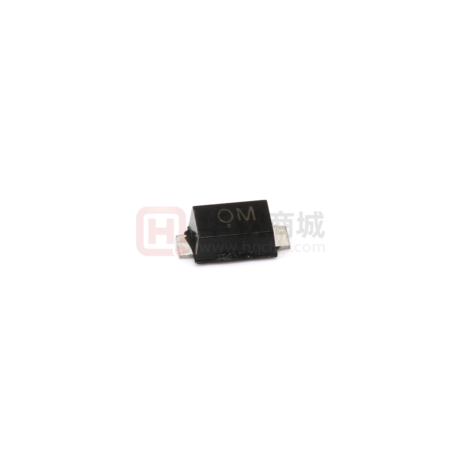
SMF5.0A(CA)-SMF58A(CA)
SURFACE MOUNT TRANSIENT VOLTAGE SUPPESSOR DIODE
Features
! For surface mounted applications
! Low profile package
! Low incremental surge resistance, excellent
clamping capability
! 200W peak pulse power capability with a 10/1000 µ s
wave from,repetition rate (duty cycle):0.01%
! High temperature soldering guaranteed:
260 ℃/10 seconds, at terminals
B
C
E
SOD-123FL
Dim Min Max Typ
A 3.58 3.72 3.65
3
B 2.72 2.78 2.75
C 1.77 1.83 1.80
D
1
1.02
1.08 1.05
E 0.097 1.03 1.00
H 0.13 0.17 0.15
L
0.53 0.57 0.55
All Dimensions in mm
Mechanical Data
! Case: JEDEC SOD-123FL, molded plastic
over passivated chip
! Polarity: Color band denotes positive end
D
H
L
( cathode ) except for bidirectional
! Mounting position: Any
!
E
Weight: 0.006 ounces, 0.02 gram
A
Maximum Ratings TA = 25�C unless otherwise specified
Characteristic
Symbol
Value
Unit
Maximum P PK Dissipation (PW - 10/1000 μs)
PPK
200
W
Maximum P PK Dissipation @ Ta = 25 °C (PW - 8/10 μs) (Note 2)
PPK
1000
W
DC Power Dissipation @ Ta = 25 °C
PD
385
mW
4.0
mW/ °C
(Note 3)
Derate above 25 °C
Thermal Resistance, Junction to Ambient (Note 3)
RӨJA
325
°C/W
Thermal Resistance, Junction to Lead (Note 3)
RӨJL
26
°C/W
TJ, TSTG
-55 to +150
°C
Operating Junction and Storage Temperature Range
Notes :
(1) Non−repetitive current pulse at Ta = 25°C, per waveform of Fig. 2.
(2) Non−repetitive current pulse at Ta = 25°C, per waveform of Fig. 5.
(3) Mounted with recommended minimum pad size, DC board FR
−4.
www.slkormicro.com
1
�SMF5.0A(CA)-SMF58A(CA)
Marking
TYPE
(Bi)
(Uni)
(Bi)
SMF5.0A
SMF6.0A
SMF6.5A
SMF7.0A
SMF7.5A
SMF8.0A
SMF8.5A
SMF9.0A
SMF10A
SMF11A
SMF12A
SMF13A
SMF14A
SMF15A
SMF16A
SMF17A
SMF18A
SMF20A
SMF22A
SMF24A
SMF26A
SMF28A
SMF30A
SMF33A
SMF36A
SMF40A
SMF43A
SMF45A
SMF5.0CA
SMF6.0CA
SMF6.5CA
SMF7.0CA
SMF7.5CA
SMF8.0CA
SMF8.5CA
SMF9.0CA
SMF10CA
SMF11CA
SMF12CA
SMF13CA
SMF14CA
SMF15CA
SMF16CA
SMF17CA
SMF18CA
SMF20CA
SMF22CA
SMF24CA
SMF26CA
SMF28CA
SMF30CA
SMF33CA
SMF36CA
SMF40CA
SMF43CA
SMF45CA
AE
NE
AG
AK
AM
NG
NK
AP
AR
NP
NR
AT
AV
NT
NV
AX
AZ
BE
NX
NZ
OE
BG
OG
BK
BM
OK
OM
BP
BR
BT
BV
BX
OP
OR
OT
BZ
CE
OZ
PE
CG
CK
CM
PG
PK
PM
CP
CR
CT
PP
PR
PT
CV
PV
SMF48A
SMF48CA
SMF51CA
SMF54CA
SMF58CA
CX
PX
CZ
CA
PZ
PA
CC
PC
(Uni)
SMF51A
SMF54A
SMF58A
www.slkormicro.com
NM
OV
OX
Reverse
Stand-Off
Voltage
VRWM (V)
5.0
6.0
6.5
7.0
7.5
8.0
8.5
9.0
10
11
12
13
14
15
16
17
18
20
22
24
26
28
30
33
36
40
43
45
48
51
54
58
Breakdown Breakdown
Test
Voltage Current
Voltage
Max. @ IT
Min. @IT
VBR MIN(V)
VBR MAX(V) IT (mA)
7.00
7.37
7.98
8.60
9.21
9.83
10.4
11.1
12.3
13.5
14.7
15.9
17.2
18.5
19.7
20.9
22.1
24.5
26.9
29.5
31.9
34.4
36.8
40.6
44.2
49.1
52.8
55.3
58.9
62.7
66.3
71.2
6.40
6.67
7.22
7.78
8.33
8.89
9.44
10.0
11.1
12.2
13.3
14.4
15.6
16.7
17.8
18.9
20.0
22.2
24.4
26.7
28.9
31.1
33.3
36.7
40.0
44.4
47.8
50.0
53.3
56.7
60.0
64.4
2
10
10
10
10
1.0
1.0
1.0
1.0
1.0
1.0
1.0
1.0
1.0
1.0
1.0
1.0
1.0
1.0
1.0
1.0
1.0
1.0
1.0
1.0
1.0
1.0
1.0
1.0
1.0
1.0
1.0
1.0
Reverse
Leakage
@VRWM
Maximum
Clamping
Voltage
@IPP
IR(uA)
VC(V)
IPP(mA)
400
400
250
100
50
25
10
5.0
2.5
2.5
2.5
1.0
1.0
1.0
1.0
1.0
1.0
1.0
1.0
1.0
1.0
1.0
1.0
1.0
1.0
1.0
1.0
1.0
1.0
1.0
1.0
1.0
9.2
10.3
11.2
12.0
12.9
13.6
14.4
15.4
17.0
18.2
19.9
21.5
23.2
24.4
26.0
27.6
29.2
32.4
35.5
38.9
42.1
45.4
48.4
53.3
58.1
64.5
69.4
72.7
77.4
82.4
87.1
93.6
21.7
19.4
17.9
16.7
15.5
14.7
13.9
13.0
11.8
11.0
10.1
9.3
8.6
8.2
7.7
7.2
6.8
6.2
5.6
5.1
4..8
4.4
4.1
3.8
3.4
3.1
2.9
2.8
2.6
2.4
2.3
2.1
Peak
Pulse
Current
�SMF5.0A(CA)-SMF58A(CA)
FIG.2 - 10 x 1000 μs PULSE WAVEFORM
120
Pulse Width (tp) is defined
as that point where the peak
current decays to 50% of IRSM
tr
100
100
tr ≤ 10 μs
80
VALUE (%)
PEAK PULSE DERATING IN % OF
PEAK POWER OR CURRENT
FIG.1 - PULSE DERATING CURVE
60
40
Peak Value - I RSM
50
Half Value - IRSM
2
Ta = 25 °C
20
tp
0
0
0
25
50
100
75
125
150
0
1
Ta, AMBIENT TEMPERATURE, ( °C)
3
4
t, TIME (ms)
FIG.3 - STEADY STATE POWER DERATING
FIG.4 - PULSE RATING CURVE
4.0
10000
Pp,PEAK POWER (W)
PD, STEADY STATE POWER
DISSIPATION (W)
2
3.0
2.0
1.0
1000
100
10
0.1μs
1.0μs
10μs
100μs
1.0ms
10ms
0
25
50
75
100
125
150
tp, PULSE WIDTH
175
TL, LEAD TEMPERATURE (°C)
FIG. 6 - CAPACITANCE VS. WORKING PEAK
REVERSE VOLTAGE
1000
Pulse Width (tp) is defined
as that point where the peak
current decays = 8 μs
tr
100
Measured @ Zero Bias
C, CAPACITANCE (pF)
% OF PEAK PULSE CURRENT
FIG.5 - 8 x 20 μs PULSE WAVEFORM
Peak Value I RSM @ 8 μs
Half Value I RSM/ 2 @ 20 μs
50
tp
0
0
20
40
60
80
t, TIME (μs)
www.slkormicro.com
100
Measured @ 50 %VRWM
10
1
1
10
100
WORKING PEAK REVERSE VOLTAGE (V)
3
200
�
很抱歉,暂时无法提供与“SMF15CA”相匹配的价格&库存,您可以联系我们找货
免费人工找货- 国内价格
- 1+0.11401
- 100+0.10641
- 300+0.09881
- 500+0.09120
- 2000+0.08740
- 5000+0.08512
