M12 Series Metal Barrel Sensors
Datasheet
Rugged, self-contained sensors in a 12 mm threaded barrel
•
•
•
•
•
•
Complete family of sensors, all housed in a compact 12 mm
threaded metal barrel
Opposed, retroreflective, polarized retroreflective, diffuse and
25, 50, or 75 mm cutoff fixed-field mode operation, depending
on model
Excellent background suppression on fixed-field models; an
excellent alternative to proximity sensors
Two signal indicator LEDs for easy operating status monitoring
from any direction
10 V dc to 30 V dc operation
Complementary solid-state outputs (one normally open, one
normally closed); PNP or NPN, depending on model
WARNING:
• Do not use this device for personnel protection
• Using this device for personnel protection could result in serious injury or death.
• This device does not include the self-checking redundant circuitry necessary to allow its use in personnel safety
applications. A device failure or malfunction can cause either an energized (on) or de-energized (off) output condition.
Models
Models1
Sensing Mode
Sensing Beam
Range
Output
660 nm Visible Red
5 m (16.4 ft)
PNP
M12E
N/A
M12PR
M12NR
M12PLP
M12NLP
2
OPPOSED
NPN
PNP
P
660 nm Visible Red
1.5 m (4.9 ft) 3
NPN
660 nm Visible Red
2.5 m (8.2 ft) 3
NPN
660 nm Visible Red
400 mm (15.7 in)
NPN
POLAR RETRO
M12PLV
PNP
M12NLV
RETRO
M12PD
PNP
DIVERGENT
M12ND
DIFFUSE
4
M12PFF25
25 mm (1 in) cutoff; 25 mm (1 in) focus
M12NFF25
M12PFF50
M12NFF50
M12PFF75
680 nm Visible Red
FIXED-FIELD
4
75 mm (3 in) cutoff; 25 mm (1 in) focus
M12NFF75
1
2
3
4
50 mm (2 in) cutoff; 25 mm (1 in) focus
PNP
NPN
PNP
NPN
PNP
NPN
Only standard 2 m (6.5 ft) cable models are listed. For 9 m (30 ft) cable, add suffix "W/30" to the model number (for example, M12E W/30). Quick-disconnect models:
• 4-pin integral Euro-style M12 connector: add suffix "Q8" (for example, M12EQ8)
• 4-pin 150 mm (6 in) Euro-style connector: add suffix "Q5" (for example, M12EQ5)
Effective Beam: 10 mm (0.39 in)
Retroreflective range is specified using one model BRT-84 retroreflector. Actual sensing range may be more or less than specified, depending upon efficiency and reflective area
of the retroreflector(s) used.
Performance based on use of 90% reflectance white test card.
Original Document
129721 Rev. F
3 May 2019
129721
�M12 Series Metal Barrel Sensors
Overview
Banner's M12 family of sensors offers a full complement of sensing modes,
all packaged in a compact yet rugged metal housing. The 12 mm barrel
design allows them to mount easily into tight spaces, with the excellent
performance expected of much larger sensors.
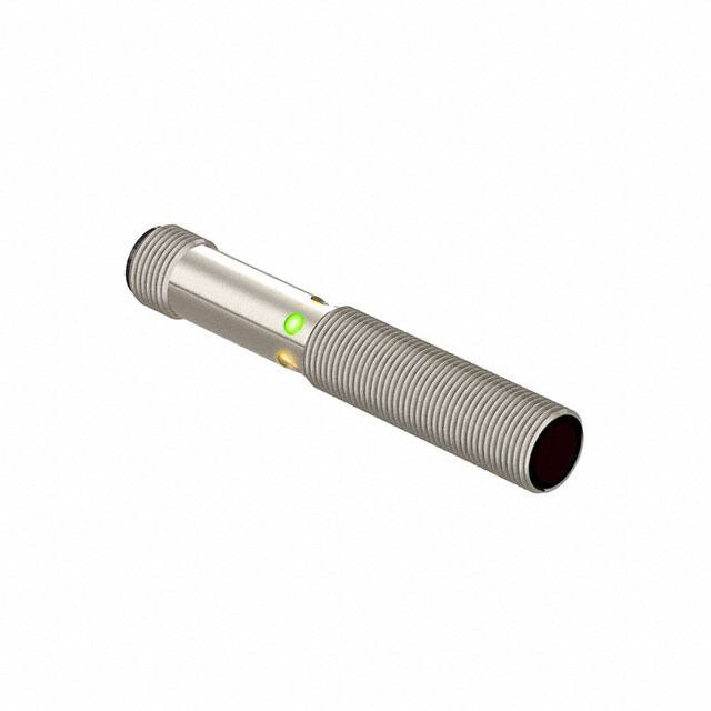
The single-turn Gain potentiometer on most models and two Signal LEDs
(positioned on either side of the housing for visibility) provide easy
alignment and configuration for reliable sensing (see Figure 1 on page 2).
Note that when the signal LED is not ON, the green Power LED is visible
through all three LED ports.
Power LED
Single-turn Gain
Potentiometer
Signal LED
(x2)
Figure 1. Features
LED Status
Description
Green ON Steady
Power ON
Green Flashing
Output overloaded
Amber ON Steady
Light Sensed
Amber Flashing
Marginal excess gain
Fixed-Field Mode Overview
M12 Series fixed-field sensors are powerful diffuse-mode sensors with far-limit cutoff (a type of background suppression). Their high excess gain
and fixed-field technology allow them to detect objects of low reflectivity that are directly in front of another surface, while ignoring the surface in the
background.
The cutoff distance is fixed. Background and background objects must always be placed beyond the cutoff distance.
As a general rule, the most reliable sensing of an object approaching from the side occurs when the line of approach is parallel to the sensing axis.
Fixed-Field Sensing – Theory of Operation
The M12FF compares the reflections of its emitted light beam (E) from an object back to the sensor's two differently aimed detectors, R1 and R2.
See Figure 2 on page 2. If the near detector's (R1) light signal is stronger than the far detector's (R2) light signal (see object A in the Figure below,
closer than the cutoff distance), the sensor responds to the object. If the far detector's (R2) light signal is stronger than the near detector's (R1) light
signal (see object B in the Figure below, beyond the cutoff distance), the sensor ignores the object.
The cutoff distance for the model M12FF sensors is fixed at 25, 50, or 75 mm (1 in, 2 in, or 3 in). Objects lying beyond the cutoff distance are usually
ignored, even if they are highly reflective. However, under certain conditions, it is possible to falsely detect a background object (see Background
Reflectivity and Placement on page 3).
Receiver
Elements
Near R1
Detector
Cutoff
Distance
Object B
or
Background
Object
A
Lenses
Far
R2
Detector
Emitter
E
Sensing
Range
E
R2
R1
Object is sensed if amount of light at R1
is greater than the amount of light at R2
Figure 2. Fixed-Field Concept
Sensing
Axis
Figure 3. Fixed-Field Sensing Axis
In the drawings and information provided in this document, the letters E, R1, and R2 identify how the sensor's three optical elements (Emitter "E",
Near Detector "R1", and Far Detector "R2") line up across the face of the sensor. The location of these elements defines the sensing axis, see Figure
3 on page 2. The sensing axis becomes important in certain situations, such as those illustrated in Figure 6 on page 3 and Figure 7 on page 3.
2
www.bannerengineering.com - Tel: + 1 888 373 6767
P/N 129721 Rev. F
�M12 Series Metal Barrel Sensors
Configuration Instructions
Sensing Reliability
For highest sensitivity, position the target for sensing at or near the point of maximum excess gain. See Performance Curves section for the excess
gain curves. Sensing at or near this distance makes the maximum use of each sensor’s available sensing power. The background must be placed
beyond the cutoff distance. Note that the reflectivity of the background surface also may affect the cutoff distance. Following these guidelines
improves sensing reliability.
Background Reflectivity and Placement
Avoid mirror-like backgrounds that produce specular reflections. A false sensor response occurs if a background surface reflects the sensor's light
more to the near detector (R1) than to the far detector (R2). The result is a false ON condition (Figure 4 on page 3). Correct this problem by using
a diffusely reflective (matte) background, or angling either the sensor or the background (in any plane) so the background does not reflect light back
to the sensor (Figure 5 on page 3). Position the background as far beyond the cutoff distance as possible.
An object beyond the cutoff distance, either stationary (and when positioned as shown in Figure 6 on page 3), or moving past the face of the
sensor in a direction perpendicular to the sensing axis, may cause unwanted triggering of the sensor if more light is reflected to the near detector
than to the far detector. Correct the problem by rotating the sensor 90° (Figure 7 on page 3). The object then reflects the R1 and R2 fields equally,
resulting in no false triggering. A better solution, if possible, may be to reposition the object or the sensor.
E = Emitter
R2 = Far Detector
R1 = Near Detector
M12..FF..
E
R2
R1
Cutoff
Distance
Cutoff
Distance
Fixed Sensing
Field
Reflective
Background
Core of
Emitted
Beam
Strong
Direct
Reflection
to R1
M12..FF..
E
R2
R1
Fixed
Sensing
Field
Core of
Emitted
Beam
Strong
Direct
Reflection
Away
From Sensor
E = Emitter
R2 = Far Detector
R1 = Near Detector
Figure 4. Reflective Background - Problem
Reflective
Background
Figure 5. Reflective Background - Solution
Cutoff
Distance
Cutoff
Distance
M12..FF..
M12..FF..
E
R2
R1
E = Emitter
R2 = Far Detector
R1 = Near Detector
E, R2, R1
Fixed
Sensing
Field
Fixed
Sensing
Field
Reflective
Background
or
Moving Object
E = Emitter
R2 = Far Detector
R1 = Near Detector
Reflective
Background
or
Moving Object
A reflective background object in this position or moving across the sensor face in this
axis and direction may cause a false sensor response.
A reflective background object in this position or moving across the sensor face in this
axis is ignored.
Figure 6. Object Beyond Cutoff - Problem
Figure 7. Object Beyond Cutoff - Solution
Color Sensitivity
The effects of object reflectivity on cutoff distance, though small, may be important for some applications. It is expected that at any given cutoff
setting, the actual cutoff distance for lower reflectance targets is slightly shorter than for higher reflectance targets. This behavior is known as color
sensitivity.
These excess gain curves were generated using a white test card of 90% reflectance. Objects with reflectivity of less than 90% reflect less light back
to the sensor, and thus require proportionately more excess gain in order to be sensed with the same reliability as more reflective objects. When
sensing an object of very low reflectivity, it may be especially important to sense it at or near the distance of maximum excess gain.
P/N 129721 Rev. F
www.bannerengineering.com - Tel: + 1 888 373 6767
3
�M12 Series Metal Barrel Sensors
Wiring Diagrams
3
3
1
–
1
10-30V dc
4
+
2
Figure 8. Emitter
1
4
2
Load
Load
Figure 9. NPN Models
+
10-30V dc
–
3
–
10-30V dc
+
Load
Key
1 = Brown
2 = White
3 = Blue
4 = Black
Load
Figure 10. PNP Models
Quick disconnect wiring diagrams are functionally identical.
Installation Instructions
Mount the Device
1. If a bracket is needed, mount the device onto the bracket.
2. Mount the device (or the device and the bracket) to the machine or equipment at the desired location. Do not tighten the mounting screws at
this time.
3. Check the device alignment.
4. Tighten the mounting screws to secure the device (or the device and the bracket) in the aligned position.
Specifications
Sensing Beam
Fixed Field Models: Visible red, 680 nm
All Other Models: Visible red, 660 nm
Supply Voltage and Current
10 V dc to 30 V dc (10% max. ripple) at 20 mA current, exclusive of load
Supply Protection Circuitry
Protected against reverse polarity and transient voltages
Output Configuration
Complementary (one normally open and one normally closed) solid-state, NPN, or
PNP, depending on model
Output Ratings
100 mA total across both outputs with overload and short circuit protection
OFF-state leakage current:
• NPN: less than 200 µA at 30 V dc (see Application Note)
• PNP: less than 10 µA at 30 V dc
ON-state saturation voltage:
• NPN: less than 1.6 V at 100 mA
• PNP: less than 3.0 V at 100 mA
Output Protection Circuitry
Protected against output short-circuit and false pulse on power up
Output Response Time
Opposed Mode: 625 µs ON/375 µs OFF
All Other Modes: 500 µs ON and OFF
Note: 100 ms delay on power-up; outputs do not
conduct during this time.
4
Repeatability
Opposed Mode: 85 µs
All Other Modes: 95 µs
Indicators
Two Status (amber) and one Power (green) LED (see Figure 1 on page 2)
Adjustments
Fixed-Field Models: None
All Other Models: Single-turn Gain (sensitivity) potentiometer
Construction
Housing: Nickel-plated brass
Lenses: PMMA
Cable Endcap and Gain Potentiometer Adjuster: PBT
Environmental Rating
IEC IP67; NEMA 6, IEC IP68, and 1200 PSI washdown, NEMA ICS 5 Annex F-2002
Connections
2 m (6.5 ft) or 9 m (30 ft) 4-wire PVC-jacketed cable, Integral 4-pin M12/Euro-style
quick disconnect fitting, or 4-pin 150 mm (6 in) M12/Euro-style fitting, depending on
model
Operating Conditions
Operating Temperature: –20 °C to +60 °C (–4 °F to +140 °F)
90% at +50 °C maximum relative humidity (non-condensing)
Application Notes
NPN off-state leakage current is < 200 µA for load resistances > 3 kΩ or optically
isolated loads. For load current 100 mA, leakage is


 工商网监
湘ICP备2023018690号
工商网监
湘ICP备2023018690号
