VTB Pick-to-Light Optical Touch Button
Instruction Manual
Ergonomic optical touch button for pick-to-light applications
•
•
•
•
•
•
•
•
•
Microcontroller-based photoelectric touch buttons
A cost-effective and easy-to-install alternative to capacitive touch switches and
mechanical push buttons for error proofing and parts-verification applications
Ergonomically designed to eliminate hand, wrist, and arm stresses associated with
repeated switch operation; requires no physical pressure to operate
Illuminated base provides a bright, easy-to-see job light in one or two colors,
depending on model
LED power and output indicators
NPN or PNP output, depending on model
Immune to ambient light, EMI and RFI interference
High excess gain cuts through heavy airborne contamination to function in almost any
environment
Pre-installed field covers protect the device and prevent inadvertent activation
WARNING:
• Do not use this device for personnel protection
• Using this device for personnel protection could result in serious injury or death.
• This device does not include the self-checking redundant circuitry necessary to allow its use in
personnel safety applications. A device failure or malfunction can cause either an energized (on) or deenergized (off) output condition.
Models
One-Color Job Light Models
Job Light Color
Cable 1
Green
Red
Blue
VTBN6
VTBN6R
VTBN6B
2 m 4-wire cable
VTBN6Q
VTBN6RQ
VTBN6BQ
4-pin Euro QD
VTBN6L
VTBN6RL
VTBN6BL
2 m 4-wire cable
VTBN6LQ
VTBN6RLQ
VTBN6BLQ
4-pin Euro QD
VTBP6
VTBP6R
VTBP6B
2 m 4-wire cable
VTBP6Q
VTBP6RQ
VTBP6BQ
4-pin Euro QD
VTBP6L
VTBP6RL
VTBP6BL
2 m 4-wire cable
VTBP6LQ
VTBP6RLQ
VTBP6BLQ
4-pin Euro QD
Upper Housing
Output Type
Job Light Input
NPN
0 V DC
PNP
+4 V DC to 30 V DC
Output Type
Job Light Input
NPN
0 V DC
PNP
+4 V DC to 30V DC
Polysulfone
Polycarbonate
Polysulfone
Polycarbonate
Two-Color Job Light Models
Green and Red (see Wiring)
Cable 1
VTBN6GR
2 m 5-wire cable
VTBN6GRQ
5-pin Euro QD
VTBN6GRL
2 m 5-wire cable
VTBN6GRLQ
5-pin Euro QD
VTBP6GR
2 m 5-wire cable
VTBP6GRQ
5-pin Euro QD
VTBP6GRL
2 m 5-wire cable
VTBP6GRLQ
5-pin Euro QD
Upper Housing
Polysulfone
Polycarbonate
Polysulfone
Polycarbonate
1 To order the 9 m (30 ft) cable models, add the suffix "W/30" to the cabled model number. (For example, VTBN6 W/30.) Models with a quick disconnect
connector require a mating cable. (See Quick Disconnect (QD) Cables on p. 4).
Original Document
67570 Rev. G
27 January 2021
67570
�VTB Pick-to-Light Optical Touch Button
Overview
Banner VTB Series touch buttons are ergonomically designed to eliminate the hand, wrist, and arm stresses associated with
mechanical push buttons. They require no physical pressure to operate. LED indicators light when power is on and outputs are
activated.
The solid-state output interfaces to a system controller, which is pre-programmed for a specific sequence of tasks. Mounted in or
near each bin in an assembler’s work station, the sensor job light signals the assembler which bins contain items to be picked in a
given operation and in what order they should be picked.
As the assembler takes a part in sequence, then reaches a finger into the yoke of the corresponding touch button, the sensor
senses that the part was removed and it sends an output signal to the controller. The controller then verifies if the correct part was
taken and may respond by turning that job light OFF, activating the job light of the next bin in the sequence.
If multiple parts are to be removed from one bin, the job light may remain ON until the appropriate number of signals is returned to
the controller. If an incorrect part is selected, the control system may be wired to signal an alarm for the assembler and/or a
supervisor, or it may be programmed to interpret the action as a call for parts.
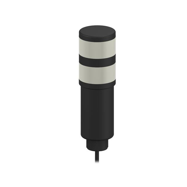
All models are immune to EMI, RFI, and ambient light interference. VTBs have either a black polysulfone or red polycarbonate
upper housing (depending on model) and a translucent white polycarbonate base. Environmental considerations for use of the two
upper housing types differ; see specifications. The entire base section lights to provide a bright job light where a task is to be
performed. The 30 mm threaded base on all models provides easy mounting.
Rugged translucent polypropylene (TP) field covers are installed on all models to prevent inadvertent switch actuation due to
objects (such as loose clothing or debris) which might accidentally block the sensing beam. The polypropylene material is capable
of absorbing high impact (even at low temperatures) and is highly resistant to abrasion and to damage by most chemicals.
EU Declaration of Conformity (DoC)
Banner Engineering Corp. herewith declares that these products are in conformity with the provisions of the listed directives and all
essential health and safety requirements have been met. For the complete DoC, please go to www.bannerengineering.com.
Product
Directive
VTB Optical Touch Buttons DC Models
EMC Directive 2014/30/EU
Representative in EU: Peter Mertens, Managing Director, Banner Engineering BV. Address: Park Lane, Culliganlaan 2F, bus 3,1831
Diegem, Belgium.
Indicators
Power ON/OFF
LED
Black Polysulfone
or Red Polycarbonate
Output
Conducting
LED
Switch
Touch
Area
Translucent White
Polycarbonate
Base/Job Light
Power ON/OFF (red):
Steady ON when power is applied
Output Conducting (red):
Steady ON when button is activated
OFF when button is not activated
Job Light:
Steady ON or flashing 2 when a task is to be
performed
Installation
Mount the Device Using the Threaded Base
1. If your device came with a lock washer or gasket, place it on the threaded base.
2. Insert the base of the device though a hole or a bracket.
• If desired and available, insert the device through an appropriately sized hole in the machine or equipment at the
desired location.
• If a bracket is needed, insert the device into the bracket.
3. Thread the mounting nut onto the base of the device, finger tight.
4. If using a bracket, mount the device and the bracket to the machine or equipment at the desired location. Do not tighten
the mounting screws at this time.
5. Check the device alignment, if precise alignment is necessary.
2
2
Flashing job light is dependent on wiring. Color is dependent on model and wiring.
www.bannerengineering.com - Tel: + 1 888 373 6767
P/N 67570 Rev. G
�VTB Pick-to-Light Optical Touch Button
6. Tighten the nut.
7. If using a bracket, tighten the mounting screws to secure the device and the bracket in the aligned position.
Wiring
Single-color models may be wired for either a solid or flashing job light. The wiring of two-color models determines the job light.
Color flashing job light is not available. Cabled model wiring shown. Cabled and QD model wiring is functionally identical.
•
•
For solid color, use the standard wiring diagram.
For flashing (2 Hz), use the alternate wiring diagrams.
One-Color Job Light, NPN (Sinking)
Output Models
One-Color Job Light, PNP (Sourcing)
Output Models
Two-Color Job Light Models
Solid Job Light
Solid Job Light
NPN (Sinking) Output Models
bn
bu
bk
wh
+
12-30V dc
-
Load
Job Light Enable
0V dc
Flashing Job Light
bn
bu
bk
wh
bn
bu
bk
wh
-
Load
Job Light Enable
+4-30 V dc
Flashing Job Light
-
12-30 V dc
+
Load
Job Light Enable
+4-30 V dc
bn
bu
bk
wh
bn
bu
bk
wh
gy
+
12-30 V dc
+
12-30V dc
-
Load
Green Job Light Enable — 0V dc
Red Job Light Enable — 0V dc
PNP (Sourcing) Output Models
-
12-30V dc
+
Load
Job Light Enable
0V dc
bn
bu
bk
wh
gy
+
12-30 V dc
-
Load
Green Job Light Enable — +4-30 V dc
Red Job Light Enable — +4-30 V dc
Specifications
Supply Voltage and Current
One-color job light models: Less than 120 mA max current at 12 V DC and
less than 70 mA max current at 30 V DC (exclusive of load)
Two-color job light models: Less than 67 mA max current at 12 V DC; less
than 40 mA max current at 24 V DC; and less than 35 mA max current at 30
V DC (exclusive of load)
Indicators
2 green LED indicators: Power ON and Output Conducting
Base lights green, red or blue (depending on model and wiring) as a job light
when input line is enabled. One-color models may be wired for flashing,
rather than solid color operation.
Supply Protection Circuitry
Protected against reverse polarity and transient voltages (fast-transient and
overvoltage)
Connections
PVC-jacketed 2 m (6.5 ft) cables or 4-pin M12/Euro-style QD fitting,
depending on model; integral 9 m (30 ft) cables are also available.
Accessory QD cables required for QD models.
Output Configuration
1 current sinking (NPN) open collector transistor or 1 current sourcing (PNP)
open collector transistor, depending on model
Ambient Light Immunity
Up to 120,000 lux (direct sunlight)
Output Rating
Max. load: 150 mA
On-state saturation voltage: < 1.5 V at 150 mA
Off-state leakage current: < 10 μA
Output Protection Circuitry
All models protected against false pulse on power-up (outputs held OFF for
1 second at power-up), overload and short-circuits.
EMI/RFI Immunity
Immune to EMI and RFI noise sources, per IEC 947-5-2
Construction
Totally encapsulated, non-metallic enclosure. Black polysulfone or red
polycarbonate upper housing (see Application Note below); translucent
white polycarbonate base. Electronics fully epoxy-encapsulated.
Protective cover: Polypropylene copolymer
Output Response Time
100 milliseconds ON/OFF
P/N 67570 Rev. G
www.bannerengineering.com - Tel: + 1 888 373 6767
3
�VTB Pick-to-Light Optical Touch Button
Operating Conditions
–20 °C to +50 °C (–4 °F to +122 °F)
90% at +50 °C maximum relative humidity (non-condensing)
Required Overcurrent Protection
Environmental Rating
Meets NEMA standards 1, 3, 4, 4X, 12, and 13; IEC IP66
Application Notes
Environmental considerations for models with polysulfone upper housings:
The polysulfone upper housing will become brittle with prolonged exposure
to outdoor sunlight. Window glass effectively filters longer wavelength
ultraviolet light and provides excellent protection from sunlight. Avoid
contact with strong alkalis. Clean periodically using mild soap solution and a
soft cloth.
Environmental considerations for models with polycarbonate upper
housings: Avoid prolonged exposure to hot water and moist high
temperature environments above 66° C (150° F). Avoid contact with
aromatic hydrocarbons (such as xylene and toluene), halogenated
hydrocarbons and strong alkalis. Clean periodically using mild soap solution
and a soft cloth.
WARNING: Electrical connections must be
made by qualified personnel in accordance with
local and national electrical codes and
regulations.
Overcurrent protection is required to be provided by end product
application per the supplied table.
Overcurrent protection may be provided with external fusing or via Current
Limiting, Class 2 Power Supply.
Supply wiring leads < 24 AWG shall not be spliced.
For additional product support, go to www.bannerengineering.com.
Certifications
Supply Wiring (AWG)
Required Overcurrent Protection (Amps)
20
5.0
22
3.0
24
2.0
26
1.0
28
0.8
30
0.5
Dimensions
Accessories
Quick Disconnect (QD) Cables
Use the 4-pin Euro-style cordsets with the one-color job light models.
4
www.bannerengineering.com - Tel: + 1 888 373 6767
P/N 67570 Rev. G
�VTB Pick-to-Light Optical Touch Button
4-Pin Threaded M12/Euro-Style Cordsets—Single Ended
Model
Length
MQDC-406
2 m (6.56 ft)
MQDC-415
5 m (16.4 ft)
MQDC-430
9 m (29.5 ft)
MQDC-450
15 m (49.2 ft)
MQDC-406RA
2 m (6.56 ft)
MQDC-415RA
5 m (16.4 ft)
MQDC-430RA
9 m (29.5 ft)
Style
Dimensions
44 Typ.
Straight
M12 x 1
ø 14.5
3
4
30 Typ.
[1.18"]
15 m (49.2 ft)
2
1
32 Typ.
[1.26"]
Right-Angle
MQDC-450RA
Pinout (Female)
1 = Brown
2 = White
3 = Blue
4 = Black
M12 x 1
ø 14.5 [0.57"]
Use the 5-pin Euro-style cordsets with the two-color job light models.
5-Pin Threaded M12/Euro-Style Cordsets—Single Ended
Model
MQDC1-501.5
Length
Style
Dimensions
0.5 m (1.5 ft)
MQDC1-506
2 m (6.5 ft)
MQDC1-515
5 m (16.4 ft)
MQDC1-530
9 m (29.5 ft)
MQDC1-506RA
2 m (6.5 ft)
MQDC1-515RA
5 m (16.4 ft)
44 Typ.
Straight
M12 x 1
ø 14.5
2
1
3
5
4
32 Typ.
[1.26"]
1 = Brown
2 = White
3 = Blue
4 = Black
5 = Gray
30 Typ.
[1.18"]
Right-Angle
MQDC1-530RA
Pinout (Female)
9 m (29.5 ft)
M12 x 1
ø 14.5 [0.57"]
Mounting Brackets
All measurements are in mm
SMB30A
•
Right-angle bracket with curved
slot for versatile orientation
•
Clearance for M6 (¼ in)
hardware
•
Mounting hole for 30 mm sensor
•
12-ga. stainless steel
45
C
61
B
A
69
Hole center spacing: A to B=40
Hole size: A=ø 6.3, B= 27.1 x 6.3, C=ø 30.5
P/N 67570 Rev. G
SMB30SC
•
Swivel bracket with 30 mm
mounting hole for sensor
•
Black reinforced thermoplastic
polyester
•
Stainless steel mounting and
swivel locking hardware
included
67
B
58
29
A
Hole center spacing: A=ø 50.8
Hole size: A=ø 7.0, B=ø 30.0
www.bannerengineering.com - Tel: + 1 888 373 6767
5
�VTB Pick-to-Light Optical Touch Button
SMB30FA
•
Swivel bracket with tilt and pan
movement for precise
adjustment
•
Mounting hole for 30 mm sensor
•
12-ga. 304 stainless steel
•
Easy sensor mounting to
extrude rail T-slot
•
Metric and inch size bolt
available
83.2
36.3
68.9
B
A
Bolt thread: SMB30FA, A= 3/8 - 16 x 2 in; SMB30FAM10, A= M10 - 1.5 x 50
Hole size: B= ø 30.1
SMB30MM
•
12-ga. stainless steel bracket
with curved mounting slots for
versatile orientation
•
Clearance for M6 (¼ in)
hardware
•
Mounting hole for 30 mm sensor
57
70
C
57
B
SMBAMS30RA
•
Right-angle SMBAMS series
bracket
•
30 mm hole for mounting
sensors
•
Articulation slots for 90°+
rotation
•
12-ga. (2.6 mm) cold-rolled steel
45
C
53
A
B
48
Hole center spacing: A=26.0, A to B=13.0
Hole size: A=26.8 x 7.0, B=ø 6.5, C=ø 31.0
SMBAMS30P
•
Flat SMBAMS series bracket
•
30 mm hole for mounting
sensors
•
Articulation slots for 90°+
rotation
•
12-ga. 300 series stainless steel
45
C
93
A
B
A
Hole center spacing: A = 51, A to B = 25.4
Hole size: A = 42.6 x 7, B = ø 6.4, C = ø 30.1
Hole center spacing: A=26.0, A to B=13.0
Hole size: A=26.8 x 7.0, B=ø 6.5, C=ø 31.0
Banner Engineering Corp. Limited Warranty
Banner Engineering Corp. warrants its products to be free from defects in material and workmanship for one year following the date of shipment. Banner Engineering Corp. will repair or
replace, free of charge, any product of its manufacture which, at the time it is returned to the factory, is found to have been defective during the warranty period. This warranty does not
cover damage or liability for misuse, abuse, or the improper application or installation of the Banner product.
THIS LIMITED WARRANTY IS EXCLUSIVE AND IN LIEU OF ALL OTHER WARRANTIES WHETHER EXPRESS OR IMPLIED (INCLUDING, WITHOUT LIMITATION, ANY WARRANTY OF
MERCHANTABILITY OR FITNESS FOR A PARTICULAR PURPOSE), AND WHETHER ARISING UNDER COURSE OF PERFORMANCE, COURSE OF DEALING OR TRADE USAGE.
This Warranty is exclusive and limited to repair or, at the discretion of Banner Engineering Corp., replacement. IN NO EVENT SHALL BANNER ENGINEERING CORP. BE LIABLE TO
BUYER OR ANY OTHER PERSON OR ENTITY FOR ANY EXTRA COSTS, EXPENSES, LOSSES, LOSS OF PROFITS, OR ANY INCIDENTAL, CONSEQUENTIAL OR SPECIAL DAMAGES
RESULTING FROM ANY PRODUCT DEFECT OR FROM THE USE OR INABILITY TO USE THE PRODUCT, WHETHER ARISING IN CONTRACT OR WARRANTY, STATUTE, TORT,
STRICT LIABILITY, NEGLIGENCE, OR OTHERWISE.
Banner Engineering Corp. reserves the right to change, modify or improve the design of the product without assuming any obligations or liabilities relating to any product previously
manufactured by Banner Engineering Corp. Any misuse, abuse, or improper application or installation of this product or use of the product for personal protection applications when the
product is identified as not intended for such purposes will void the product warranty. Any modifications to this product without prior express approval by Banner Engineering Corp will
void the product warranties. All specifications published in this document are subject to change; Banner reserves the right to modify product specifications or update documentation at
any time. Specifications and product information in English supersede that which is provided in any other language. For the most recent version of any documentation, refer to:
www.bannerengineering.com.
For patent information, see www.bannerengineering.com/patents.
© Banner Engineering Corp. All rights reserved
�


 工商网监
湘ICP备2023018690号
工商网监
湘ICP备2023018690号
