MOD Series
M Series
MC Series MCS Series
VP Series
100 Series
S Series
Series
Operating voltage up to 100 kVDC
Operating current up to 80 Amps
Advanced contact technology
Oil tight receptacles available
High performance insulation materials PTFE
�General characteristics and
technical data Series 100
Series
Housing
Locking system
threaded coupling
Mounting type (panel mount connector)
round flange
Housing material
brass (CuZn)
Surface plating
nickel (Ni)
Protection class (mated connector)
IP67
Operating temperature
-30°C to +80°C
100 Series
Contacts 2.5 mm (connector types SB1x0)
Termination method
solder (male contact), solder / screw (female contact)
Rated current
30 A
Max. operating current
40 A
Pulse current
3000 A
Contact resistance
300 µΩ
Contact diameter
2.5 mm [.173"]
Contact diameter
AWG 14 / 2.5 mm²
Contact material
brass (CuZn)
Contact plating
silver (Ag)
Insertion / Withdrawal force
5,5 N / 4,0 N
Matiazng cycles
100000
Rated temperature
+120°C
Contacts 5 mm (connector types SB1x5)
Termination method
solder (male contact), solder / screw (female contact)
Rated current
80 A
Max. operating current
110 A
Pulse current
10000 A
Contact resistance
150 µΩ
Contact diameter
5 mm [.197"]
Max. wire size
AWG 8 / 10 mm²
Contact material
brass (CuZn)
Contact plating
silver (Ag)
Insertion / Withdrawal force
15 N / 10 N
Mating cycles
100000
Rated temperature
+120°C
Insulation inserts
Number of contacts
1
Insulation material
PTFE
CTI value
600
Flammability class PTFE
UL94 V-0
Operating temperature PTFE
-50°C to +200°C
Insulating material group PTFE / POM
I (DIN IEC 60664)
Suitable cable dimensions
max. Ø 14.0 mm [.551"]
max. Ø 10.0 mm [.394"]
type 1x0: max. AWG14
type 1x5: max. AWG8
28
�Type SB155 50
Series
kVDC
GB155 receptacle, panel mount (standard / oil tight)
GB155 receptacle,
panel mount
panel cut out
rear view
100 Series
KS155 plug, cable mount, with integrated cable gland
KS155 plug,
cable mount
Electrical values
Operating voltage (DC)
50 kV
Test voltage (DC)
75 kV
Rated current
80 A
Maximum operating current
110 A
Pulse current
10000 A
front view
KS155 plug, cable mount, with M20/M25 adapter for external cable gland
Characteristics
Contact size
5 mm [.197"]
Insulation material
PTFE
Mounting type receptacle
round flange
Contact plating
silver (Ag)
front view
drawing - dimensions in mm [inch]
P/N
Description
Plug,
cable
mount
Receptacle,
panel
mount
7200551
KS155/6,5-8 PTFE
7200550
KS155/8-9,5 PTFE
7200552
KS155/9,5-11 PTFE
7200554
KS155/11-12,5 PTFE
7200553
KS155/12,5-14 PTFE
7200555
KS155/M20 PTFE
7200556
KS155/M25 PTFE
7200557
GB155 PTFE
7200558
GB155/Ö PTFE
clamping range
for cables
Ø 6.5 - 8 mm
[.256" - .315"]
clamping range
for cables
Ø 8 - 9.5 mm
[.315" - .374"]
clamping range
for cables
Ø 9.5 - 11 mm
[.374" - .433"]
clamping range
for cables
Ø 11 - 12.5 mm
[.433" - .492"]
clamping range
for cables
Ø 12.5 - 14 mm
[.492" - .551"]
oil tight
version
with adapter M20x1.5 for external cable gland
with adapter M25x1.5 for external cable gland
*KV = screwed cable gland
Accessories - page 42
Mounting instructions - page 44-47
Cables - page 48-49
© GES Electronic & Service GmbH
www.ges-electronic.de
37
�Assembly Instructions Series 100
(plug, cable mount)
5.
1.
Remove cable jacket
! Do not damage shield braid
100 Series
Part as delivered
2.
Components
Cap (1), sealing insert (2), housing (3),
insulator (4)
3.
Types
min. L1 mm [inch]
S110 / S115
52 [2.037"]
S120 / S125 / S125 Pro
72 [2.824"]
S130 / S135
92 [3.611"]
S150 / S155
142 [5.580"]
S160 / S165
224 [8.828"]
S1100 / S1105
377 [14.852"]
6.
Remove snap ring (5) and take out male
contact (6)
4.
Cut shield braid roughly about 30 mm [1.181"] (=L2)
! �Carefully remove shield parts. Loose shield
parts can cause electrical break down
7.
Place cap (1) and sealing insert (2) on cable
! Respect correct order of parts (see picture)
44
Series
© GES Electronic & Service GmbH
Completely widen shield braid. Push seal
insert (2) under shield braid
www.ges-electronic.de
�Assembly Instructions Series 100
(plug, cable mount)
Series
8.
12.
Completely insert cable in insulation part (4)
until seal insert (2) plugs in housing (3)
100 Series
Cut shield to length.
! For length see step 9.
13.
9.
Make sure shield length is between min.
and max. mark.
Screw cap (1) onto housing (3)
! Wrench size housing SW23, Wrench size
cap SW26, tightening torque 10 Nm
14.
10.
Remove dielectric insulation
Types
min. L3 mm
[inch]
KS 110/120/130/150/160/1100
5 [.197"]
KS 115/125/125 Pro/135/155/165/1105
8 [.315"]
!
Secure contact (6) with snap ring (5)
Do not damage conductor
15.
11.
Assembly finished
Solder contact (6) on conductor
! T
� in-solder must not remain on contact
surface
© GES Electronic & Service GmbH
www.ges-electronic.de
45
�Assembly Instructions Series 100
(receptacle, panel mount)
1.
4.
Part as supplied
100 Series
Series
Place counter nut (1) on cable
2.
5.
!
Remove counter nut (1) from
housing (2)
3.
ONLY when using shielded cable:
Remove cable jacket
Type
min. L2 mm [inch]
B 110 / 115
40 [1.575"]
B 120 / 125
80 [3.150"]
B 130 / 135
120 [4.724"]
B 150 / 155
200 [7.874"]
B 160 / 165
240 [9.449"]
B 1100 / 1105
400 [15.748"]
!
Do not damage shield braid
6.
Panel cut out
Dimension
Value mm [inch]
D1
36.10 [1.421"]
L1
34.90 [1.374"]
Fold back shield braid over jacket
46
© GES Electronic & Service GmbH
www.ges-electronic.de
�Assembly Instructions Series 100
(receptacle, panel mount)
Series
7.
10.
Assembly finished
Type
min. L3 mm [inch]
B 110 / 120 / 130 / 150 / 160 / 1100
5 [.197"]
B 115 / 125 / 135 / 155 / 165 / 1105
8 [.315"]
!
100 Series
Remove dielectric insulation
Do not damage conductor.
8.
Solder conductor on female contact or use a
cable lug to connect conductor with contact
! Tin-solder must not remain on contact surface
9.
!
Note – important!
Screw on counter nut and tighten
1. Please carefully read assembly
instructions before cable assembly.
2. Cable assembly must only be done
by trained and qualified personnel.
© GES Electronic & Service GmbH
www.ges-electronic.de
47
�Stripping lengths for shielded cables
Series
IMPORTANT – PLEASE NOTE:
100 Series
Stated stripping lengths are referring
ONLY to jackets of shielded cables!
48
© GES Electronic & Service GmbH
www.ges-electronic.de
�
很抱歉,暂时无法提供与“7200551”相匹配的价格&库存,您可以联系我们找货
免费人工找货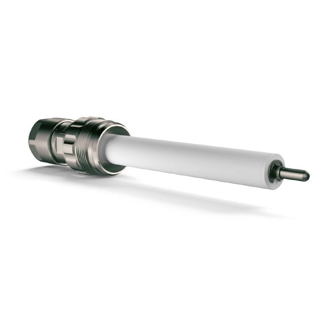


 工商网监
湘ICP备2023018690号
工商网监
湘ICP备2023018690号
