Radiocrafts
Embedded Wireless Solutions
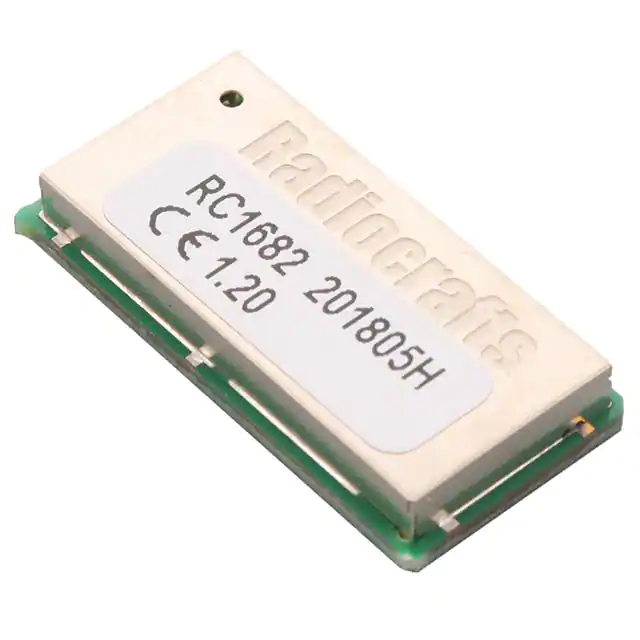
RC1682-SIG
High Performance RF Module for SIGFOX 868MHz
Product Description
The RC1682-SIG module is a compact surface-mounted product that measures only 12.7 x
25.4 x 3.7 mm. The module contains a communication controller with embedded SIGFOX protocol
software and is pre-certified for operation under the European regulations. Custom variants can
be offered with custom functionalities. How to use the embedded SIG protocol is described in
the RC16xxxx-SIG User Manual.
Applications
• Internet of Things
• Long range sensor applications
• Asset tracking and monitoring
• Telemetry stations
• Fleet management
Features
• SIGFOX compatibility (IOT)
Note: The number of LGA pads differ
from photo, see page 3 for details
• SIGFOX Class 0 category
• SIGFOX Zone 1 domain
• Long range, high reliability
• Ultra narrowband, high-performance radio
• High sensitivity and high selectivity
• High blocking properties
• Completely shielded module
• Pin compatible with other products from Radiocrafts
• 12.7 x 25.4 x 3.7 mm compact module for SMD mounting
• 2.8 – 3.6 V supply voltage
• Ultra low power modes
• Conforms with EU RED directive (EN 300 220, EN 301 489, EN 60950)
Quick Reference Data
Parameter
Uplink Frequency (TX)
Downlink Frequency (RX)
Uplink data rate (TX)
Downlink data rate (RX)
Uplink Modulation (TX)
Downlink Modulation (RX)
Max output power
Downlink sensitivity
Supply voltage VCC
Current consumption,
RX (3.3 Vvcc, 50 ohm)
Current consumption,
TX (3.3 Vvcc, 50 ohm, +14.5dBm)
Current consumption, SLEEP
Uplink Period (12 Bytes payload
transmission, without repetition)
Downlink period (listening window)
Temperature range
©2018 Radiocrafts AS
RC1682-SIG
868.13
869.525
100
600
DBPSK
GFSK
+ 14 dBm
-126
2.8 – 3.6
31
Unit
MHz
MHz
bps
bps
59
mA
Max 2.0
Max. 1.76
uA
s
Max. 25
-30 to +85
s
C
RC1682-SIG Datasheet (rev. 1.06)
dBm
dBm
Volt
mA
Page 1 of 14
�Radiocrafts
Embedded Wireless Solutions
RC1682-SIG
Typical application Circuit:
2.8 – 3.6 V
Optional
{
To host meter or
RS232/422/485
driver
GND
RTS
CTS
CONFIG
TXD
RXD
GND
GND
VCC
RESET
NC
GND
RF
GND
NC
Antenna
NC
Quick Introduction to the SIG embedded protocol
How do I transmit data?
Send your data to the RXD pin on the module. Use the UART format with settings (19200, 8,
1, N, no flow control). Up to 12 bytes payload are buffered in the module. The first byte of the
message must contain the message length (excluding the length byte itself). The module will
transmit the data when the whole packet is received.
How do I receive data?
The module has to be configured to Uplink and downlink mode in order to enable two way
communication. Any received RF data packet with correct message format (ID, key, CRC) will
be sent on the TXD pin with length byte first. The RSSI value (received signal strength) can
optionally be added to the message.
What about the antenna?
In most cases a simple quarter wavelength wire or a PCB track will do. Connect a piece of wire
to the RF pin with length corresponding to the quarter of a wavelength. For space limited
products, contact Radiocrafts and we will recommend the best antenna solution for your
application.
How do I change any configuration parameter?
To change configurable parameters, send one byte to the module with the value 0x00 or assert
the CONFIG pin. This will take the module into configuration mode. Special commands are then
used to access the configuration registers and test modes. Exit from configuration mode by
sending the ‘X’ command. Parameters can be changed permanently and stored in non-volatile
memory in the module.
SIGFOX Protocol
The RC1682-SIG module implements all the necessary features required to communicate with
the SIGFOX backend system.
The SIGFOX protocol defines two types of network modes:
1. Only uplink mode
Packets are only transmitted from the RC1682-SIG module to the base station. This
mode can be used for pure data collection.
2. Uplink and downlink mode
Packets transmitted by the RC1682-SIG module are acknowledged by the base
station. This mode can be used for controlling applications.
©2018 Radiocrafts AS
RC1682-SIG Datasheet (rev. 1.06)
Page 2 of 14
�Radiocrafts
Embedded Wireless Solutions
RC1682-SIG
Only uplink mode
Only uplink mode can be summarized as follows:
• The RC1682-SIG module transmits a frame to the base station.
• This frame is repeated 2 times (the packet is transmitted 3 times all together) with
interval. can be [0…2s] and be selected by config
parameter ‘0x27 - Retransmission number’ and is set by ‘0x2E – TX
delay’..
• Frequency hopping is implemented between packets.
Base station
Uplink
frame
RC1682-SIG
Time [s]
0...2s
Uplink and downlink mode
With Uplink and downlink mode, two way communication can be established:
• The RC1682-SIG module transmits a frame to the base station.
• The packet is retransmitted times which can be [0,1,2] with 500ms interval.
• Frequency hopping is implemented between packets.
• The Transmission (TX) window lasts until 20s measured from the end of first uplink
packet.
• The RC1682-SIG module switches to Reception (RX) mode and listens for frames for
25s.
• If a Downlink frame is received, it is decrypted and verified.
• If it is valid, the module acknowledges it with an OOB (OutOfBand) frame after a fixed
1.5s delay (requirement is 1.4s < T < 4s) and prints the decoded data of downlink frame
to UART.
1500ms
Base station
Downlink
frame
OOB
frame
Uplink
frame
RC1682-SIG
20s
TX Window
500ms
Time [s]
25s
RX Window
The embedded protocol, configuration commands and configuration memory is described in
the RC1682-SIG User Manual.
©2018 Radiocrafts AS
RC1682-SIG Datasheet (rev. 1.06)
Page 3 of 14
�Radiocrafts
Embedded Wireless Solutions
RC1682-SIG
RCTools
RCTools-SIG is a powerful and easy to use PC suite that helps you during test, development
and deployment of the RC1682-SIG. Visit www.radiocrafts.com for a free download and full
documentation.
©2018 Radiocrafts AS
RC1682-SIG Datasheet (rev. 1.06)
Page 4 of 14
�Radiocrafts
Embedded Wireless Solutions
RC1682-SIG
Block Diagram
VCC
VCC_PA
MCU
Application (option)
UART interface
SIGFOX Embedded
protocol
32 kHz
Real Time Clock
(option)
EEPROM
Narrow Band
RF Tranceiver
Balun and filtering
TCXO
(option)
Circuit Description
The module contains a communication controller with embedded SIG protocol software and a
high performance narrow band RF transceiver. As an option the module can support a real time
clock oscillator and EEPROM memory for application specific products.
The communication controller handles the radio packet protocol, the UART interface and
controls the RF transceiver. Data to be sent by the host is received at the RXD pin and buffered
in the communication controller. The data packet is then assembled before it is transmitted on
RF.
The RF transceiver modulates the data to be transmitted on RF frequency, and demodulates
data that are received. Digital signal processing technology is used to enhance sensitivity and
selectivity.
The RF power front end amplifies the signal up to +14dBm and advanced filtering topology is
included to suppress harmonics and spurs.
Received data are checked for correct CRC by the communication controller. If no CRC errors
were detected, the data packet is sent to the host on the TXD line. The data format is
configurable, and optionally an RSSI value (signal strength of received packet) can be added
to the message.
The asynchronous UART interface consists of RXD and TXD. Optionally CTS or RTS can be
used for hardware handshake flow control.
When the CONFIG pin is asserted, the module enters configuration mode and the
communication controller interprets data received on the RXD pin as configuration commands.
The module goes automatically to sleep after TX or RX to reduce the power consumption to a
minimum.
©2018 Radiocrafts AS
RC1682-SIG Datasheet (rev. 1.06)
Page 5 of 14
�Radiocrafts
Embedded Wireless Solutions
RC1682-SIG
Pin Assignment
Pin Description
Pin
no
1
2
3
4
5
6
7
8
9
10
11
12
13
14
15-18
19
20
21-42
Pin name
Description
GND
CTS/RXTX
RTS
CONFIG
TXD
RXD
GND
GND
RF
GND
VDD
Reset
VCC
GND
I/O
DD
DC
I/O
System ground
UART Clear to Send / RXTX control (RS485)
UART Request to Send
Configuration Enable. Active low.
UART TX Data
UART RX Data
System ground
System ground
RF I/O connection to antenna
System ground
Not Connected, Internal Regulator Output
RESET_N. Active Low
Supply voltage input. Internally regulated.
System ground
For future use and test status pin, Do not connect
Programming interface. See page 7 for details.
Programming interface. See page 7 for details.
For future use and test status pin, Do not connect
©2018 Radiocrafts AS
RC1682-SIG Datasheet (rev. 1.06)
Page 6 of 14
�Radiocrafts
Embedded Wireless Solutions
RC1682-SIG
Application circuit
A typical application circuit is shown where a MCU is connected to the Radiocrafts module. In
normal cases the UART (CTS/RTS is optional) and RESET line is connected to a host MCU
running the application. CONFIG pin is needed to set the SIG modules into configuration
mode.
MCU considerations
Some additional external components is needed depending on MCU output driver properties
connected to the Radiocrafts module.
If the RESET is driven by a push-pull output, an additional 0 ohm series resistor (R4) shall be
inserted as shown in the figure, to allow an external programmer used for firmware upgrade to
assert Reset low. During firmware upgrade, R4 must in this case be removed.
In noisy surroundings and where RESET is not driven by a push-pull output, it is recommended to
add an external pull-up on RESET using a 5k6 resistor (R3). If the pull-up is stronger the external
programmer used for firmware upgrade will not be able to assert RESET low.
In noisy surroundings and where RXD is not driven by a push-pull output, it is recommended to
add an external pull-up on RXD using a 5k6 resistor (R3).
©2018 Radiocrafts AS
RC1682-SIG Datasheet (rev. 1.06)
Page 7 of 14
�Radiocrafts
Embedded Wireless Solutions
RC1682-SIG
Power Supply
Noisy external circuitry may under certain scenarios affect the transmitted signal on RC1682-SIG
and precaution should be taken for EU RED conformity. Example of circuits that can generate
noise on the RC1682-SIG transmitted spectrum may be DC/DC converters and some level
converters like RS232 and RS485. To increase spectrum margin it is important to add an EMI filter
bead (L1) on the VCC pin of the RC1682-SIG module. Alternatively, the RC1682-SIG may be
powered (RC_VCC) from a separate voltage regulator. This will ensure that potential switching
noise is filtered out from the power supply (RC_VCC) to the RC1682-SIG.
Component
EMI filter bead (L1),
1500 mA
Manufacturer
Murata
Part number
Ordering code
BLM18SG331TN1
Programming Interface
For future firmware updates and possible custom variants it is recommended to include a 2x5 pins
programming connector to the module programming pins. The connector should be a 1.27 mm
pitch pin-row (same pitch in both directions), SMD or through-hole version, with the connections
shown below. RXD/TXD lines is not in use for firmware upgrade, but is included on spare pins on
the connector for debugging purposes.
©2018 Radiocrafts AS
RC1682-SIG Datasheet (rev. 1.06)
Page 8 of 14
�Radiocrafts
Embedded Wireless Solutions
RC1682-SIG
Antenna Connection
The antenna should be connected to the RF pin. The RF pin is matched to 50 Ohm. If the
antenna connector is placed away from the module at the motherboard, the track between the
RF pin and the connector should be a 50 Ohm transmission line.
On a two layer board made of FR4 the width of a microstrip transmission line should be 1.8
times the thickness of the board, assuming a dielectric constant of 4.8. The line should be run
at the top of the board, and the bottom side should be a ground plane.
Example: For a 1.6 mm thick FR4 board, the width of the trace on the top side should be 1.8 x
1.6 mm = 2.88 mm.
The simplest antenna to use is the quarter wave whip antenna. A quarter wave whip antenna
above a ground plane yields 37 Ohm impedance and a matching circuit for 50 Ohm are
usually not required.
A PCB antenna can be made as a copper track where the ground plane is removed on the
back side. The rest of the PCB board should have a ground plane as large as possible,
preferably as large as the antenna itself, to make it act as a counterweight to the antenna. If
the track is shorter than a quarter of a wavelength, the antenna should be matched to 50
ohms.
Max output power conducted of the module is +15 dBm. Using an efficient antenna (Gain > -1
dB) will give higher radiated power than limited by EU regulations (+14 dBm). A good practice
is for this reason to add a pi filter between module and antenna to be able to tune the antenna
impedance for CE compliance.
Regulatory Compliance Information
The use of RF frequencies and maximum allowed RF power is limited by national regulations.
The RC1682-SIG has been designed to comply with the RED directive 2014/53/EU when
used in European license free bands.
According to RED directives, it is the responsibility of Radiocrafts’ customers (i.e. RC1682SIG end user) to check that the host product (i.e. final product) is compliant with RED
essential requirements. The use of a CE marked radio module can avoid re-certification of the
final product, provided that the end user respects the recommendations given by Radiocrafts.
A Declaration of Conformity is available from Radiocrafts on request.
The relevant regulations are subject to change. Radiocrafts AS do not take responsibility for
the validity and accuracy of the understanding of the regulations referred above. Radiocrafts
only guarantee that this product meets the specifications in this document. Radiocrafts is
exempt from any responsibilities related to regulatory compliance.
©2018 Radiocrafts AS
RC1682-SIG Datasheet (rev. 1.06)
Page 9 of 14
�Radiocrafts
Embedded Wireless Solutions
RC1682-SIG
PCB Layout Recommendations
The recommended layout pads for the module are shown in the figure below. All dimensions
are in thousands of an inch (mil). The circle in upper left corner is an orientation mark only,
and should not be a part of the copper pattern.
The recommended layout pads for the module are shown in the figure below. All dimensions
are in thousands of an inch (mil). The circle in upper left corner is an orientation mark only,
and should not be a part of the copper pattern.
A PCB with two or more layers and with a solid ground plane in one of the inner- or bottom
layer(s) is recommended. All GND-pins of the module shall be connected to this ground plane
with vias with shortest possible routing, one via per GND-pin.
On the back side of the module there are several test pads. These test pads shall not be
connected, and the area underneath the module should be covered with solder resist. If any
routing or vias is required under the module, the routing and vias must be covered with solder
resist to prevent short circuiting of the test pads. It is recommended that vias are tented.
Reserved pins should be soldered to the pads but the pads must be left floating.
©2018 Radiocrafts AS
RC1682-SIG Datasheet (rev. 1.06)
Page 10 of 14
�Radiocrafts
Embedded Wireless Solutions
RC1682-SIG
Mechanical Drawing
Mechanical Dimensions
The module size is 12.7 x 25.4 x 3.7 mm
Carrier Tape and Reel Specification
Carrier tape and reel is in accordance with EIA Specification 481.
Tape width
44 mm
Component Hole pitch
pitch
16 mm
4 mm
Reel
diameter
13”
Units per
reel
Max 1000
Soldering Profile Recommendation
JEDEC standard IEC/JEDEC J-STD-020B (page 11 and 12), Pb-Free Assembly is
recommended.
The standard requires that the heat dissipated in the "surroundings" on the PCB is taken into
account. The peak temperature should be adjusted so that it is within the window specified in
the standard for the actual motherboard.
Aperture for paste stencil is normally areal-reduced by 20-35%, please consult your
production facility for best experience aperture reduction.
©2018 Radiocrafts AS
RC1682-SIG Datasheet (rev. 1.06)
Page 11 of 14
�Radiocrafts
Embedded Wireless Solutions
Absolute Maximum Ratings
Parameter
Min
Supply voltage, VCC
-0.3
Voltage on any pin
-0.3
Input RF level
Storage temperature
Operating temperature
-50
-40
RC1682-SIG
Max
3.9
VCC+0.3V
Max 3.9 V
10
150
85
Unit
V
V
Caution ! ESD sensitive device.
Precaution should be used when
handling the device in order to
prevent permanent damage.
dBm
C
C
Under no circumstances the absolute maximum ratings given above should be violated. Stress exceeding one or
more of the limiting values may cause permanent damage to the device.
Fresh 3.6V Li batteries normally have a higher open circuit voltage than the nominal 3.6V, but can still be used to
power the module as long as it is not exceeding the absolute maximum rating (3.9V). When the module operates in
IDLE/RX/TX the loaded battery voltage will usually drop below 3.6V, which is inside the operation voltage range
(2.8V – 3.6V).
Electrical Specifications
T=25C, VCC = 3.3V, if nothing else stated.
Parameter
Min
Operating frequency
868.13
Input/output impedance
Data rate
Typ.
Unit
MHz
600
Ohm
bps
+/-1.5
1
5
15
1 GHz
Restricted bands
Sensitivity Downlink:
Adjacent channel rejection
Alternate channel selectivity
Image channel rejection
Blocking
+/- 1 MHz
+/- 2 MHz
+/- 10 MHz
Saturation
Input IP3
Spurious emission, RX
Supply voltage, VCC
Current consumption, RX/IDLE
TX
SLEEP
Max
869.525
14
-126
62
63
58
30
35
60
83
87
91
+10
-14
dB
-57
3.6
TX period
2.0
1.76
mA
mA
uA
s
RX period
25s
s
30 %
V
Digital I/O
Input logic level, low
Input logic level, high
Output logic level, low (1µA)
Output logic level, high(-1µA)
RESET pin
Input logic level, low
Input logic level, high
UART Baud Rate tolerance
Configuration memory write cycles
©2018 Radiocrafts AS
3.3
33
58
0.6
TX: 100 bps DBPSK (uplink)
RX: 600 bps GFSK (downlink)
Including 10 years of aging.
Starting after 10 years
12.5 kHz channels
Restricted bands:
47 MHz – 74 MHz
87.5 MHz – 118 MHz
174 MHz – 230 MHz
470 MHz – 862 MHz
dBm
dB
dB
dB
dBm
dBm
dBm
V
2.8
Condition / Note
TX: 868.13 MHz (uplink mid.)
RX: 869.525 MHz (downlink)
70 %
0
Wanted signal 3 dB above
sensitivity level, CW interferer.
Apply over entire supply
voltage range
Single TX window of 12 bytes
payload without repetition.
Only in Uplink & Downlink
mode, if reply is not received.
Of VCC
Of VCC
VCC
Minimum 250 ns pulse width
30 %
V
70 %
+/- 2
%
1000
RC1682-SIG Datasheet (rev. 1.06)
UART receiver and transmitter
The guaranteed number of
write cycles using the ‘M’
command is limited
Page 12 of 14
�Radiocrafts
Embedded Wireless Solutions
RC1682-SIG
Document Revision History
Document Revision
1.00
1.01-1.02
1.03
1.04
1.05
1.06
Changes
First release
Corrected texts.
Added SIGFOX class and zone.
Corrected footer and mechanical height.
Product status changed to full production
Updated Mechanical drawing and height information. Please refer to Hardware
PCN for revision history.
Updated regulatory compliance
Product Status and Definitions
Current
Data Sheet Identification
Status
Product Status
Advance Information
Planned or under
development
Preliminary
Engineering Samples
and First Production
No Identification Noted
Full Production
Obsolete
Not in Production
X
©2018 Radiocrafts AS
RC1682-SIG Datasheet (rev. 1.06)
Definition
This data sheet contains the design
specifications for product
development. Specifications may
change in any manner without notice.
This data sheet contains preliminary
data, and supplementary data will be
published at a later date. Radiocrafts
reserves the right to make changes at
any time without notice in order to
improve design and supply the best
possible product.
This data sheet contains final
specifications. Radiocrafts
reserves the right to make
changes at any time without notice
in order to improve design and
supply the best possible product.
This data sheet contains
specifications on a product that has
been discontinued by Radiocrafts.
The data sheet is printed for
reference information only.
Page 13 of 14
�Radiocrafts
Embedded Wireless Solutions
RC1682-SIG
Disclaimer
Radiocrafts AS believes the information contained herein is correct and accurate at the time of this printing. However,
Radiocrafts AS reserves the right to make changes to this product without notice. Radiocrafts AS does not assume
any responsibility for the use of the described product; neither does it convey any license under its patent rights, or
the rights of others. The latest updates are available at the Radiocrafts website or by contacting Radiocrafts directly.
As far as possible, major changes of product specifications and functionality, will be stated in product specific Errata
Notes published at the Radiocrafts website. Customers are encouraged to check regularly for the most recent
updates on products and support tools.
Trademarks
RC232™ is a trademark of Radiocrafts AS. The RC232™ Embedded RF Protocol is used in a range of products from
Radiocrafts. The protocol handles host communication, data buffering, error check, addressing and broadcasting. It
supports point-to-point, point-to-multipoint and peer-to-peer network topologies.
All other trademarks, registered trademarks and product names are the sole property of their respective owners.
Life Support Policy
This Radiocrafts product is not designed for use in life support appliances, devices, or other systems where
malfunction can reasonably be expected to result in significant personal injury to the user, or as a critical component
in any life support device or system whose failure to perform can be reasonably expected to cause the failure of the
life support device or system, or to affect its safety or effectiveness. Radiocrafts AS customers using or selling these
products for use in such applications do so at their own risk and agree to fully indemnify Radiocrafts AS for any
damages resulting from any improper use or sale.
Radiocrafts Technical Support
Knowledge base:
Application notes library:
Whitepapers:
Technology overview:
RF Wireless Expert Training:
https://radiocrafts.com/knowledge-base/
https://radiocrafts.com/resources/application-notes/
https://radiocrafts.com/resources/articles-white-papers/
https://radiocrafts.com/technologies/
https://radiocrafts.com/resources/rf-wireless-expert-training/
Contact Radiocrafts
Sales requests: https://radiocrafts.com/contact/
© 2018, Radiocrafts AS. All rights reserved.
©2018 Radiocrafts AS
RC1682-SIG Datasheet (rev. 1.06)
Page 14 of 14
�


 工商网监
湘ICP备2023018690号
工商网监
湘ICP备2023018690号
