-|Transparent setting guide|-
MP5S/MP5Y/MP5W Series
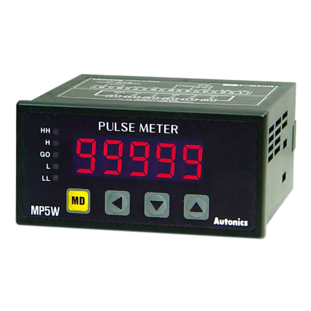
High Performance, Digital Pulse Meter
▣ Features
� otal 16 types of operation mode
T
Frequency/Revolutions/Speed, Passing speed, Cycle, Passing time,
Time interval, Time differential , Absolute ratio, Error ratio, Density,
Error, Length measurement 1, Length measurement 2, Interval,
Accumulation, Addition/Subtraction-individual input, Addition/
Subtraction-phase difference input
Various output models
Relay triple/quintuple output, NPN/PNP open collector quintuple output,
BCD dynamic output, PV transmission output (current output),
RS485 communication output (Modbus RTU)
Various functions
Selectable NPN solid state/contact input, PNP solid state/contact
input, prescale, delay monitoring, hysteresis, auto-zero time
setting, lock setting, data bank function (MP5W series)
Max. display range: -19999 to 99999
Various display units
rpm, rps, Hz, kHz, sec, min, m, mm, mm/s, m/s, m/min, m/h, ℓ/s,
ℓ/min, ℓ/h, %, counts, etc.
MP5S
MP5Y
Please read “Safety Considerations”
in the instruction manual before using.
MP5W
▣ Ordering Information
MP 5 Y - 4 N
Output
S
N
Main output
(comparative value output)
Indicator
Y
N
1
2
3
4
5
6
Indicator
NPN open collector quintuple output
PNP open collector quintuple output
Indicator
Indicator
Indicator
Relay triple output (H, GO, L)
BCD dynamic output
PV transmission output (current output)
RS485 communication output
-
N
-
1
2
Indicator
Relay quintuple output
(HH, H, GO, L, LL)
Relay triple output (H, GO, L)
NPN open collector quintuple output
BCD dynamic output
4
NPN open collector quintuple output
PV transmission output (current output)
5
8
PNP open collector quintuple output
NPN open collector quintuple output
PV transmission output (current output)
RS485 communication output
9
PNP open collector quintuple output
RS485 communication output
A
W
Power supply
Size
Digits
Item
O-76
2
24VAC 50/60Hz, 24-48VDC
4
100-240VAC 50/60Hz
S
Y
W
DIN W48×H48mm
DIN W72×H36mm
DIN W96×H48mm
5
99999 (5-digit)
MP
Pulse meter
Sub output
(display value output)
-
-
�-|Transparent setting guide|-
Pulse Meter
▣ Specifications
Series
Display method
Character size
Display range
AC voltage
Power
supply
AC/DC voltage
Power
consumption
AC voltage
AC/DC voltage
Permissible voltage range
External power supply
Sub power supply
Input frequency
Input method
Measurement range
Measurement accuracy
(23℃±5℃)
Display cycle
Operation mode
Output
Prescale function
Hysteresis
Relay triple
Main
Relay quintuple
NPN/PNP open
collector quintuple
BCD dynamic
Sub PV transmission
Communication
Memory retention
Insulation resistance
Dielectric strength
Noise immunity
Mechanical
Vibration
Malfunction
Mechanical
Shock
Malfunction
Mechanical
Relay
life cycle
Electrical
Ambient temp.
Environment
Ambient humi.
Approval
※2
Weight
MP5S
MP5Y
MP5W
7-segment LED (zero blanking method)
W4×H8mm
W7×H14mm
-19999 to 99999
100-240VACᜠ 50/60Hz
24VACᜠ 50/60Hz, 24-48VDCᜡ
Max. 7.5VA
Max. 9VA
Max. 15VA
(100-240VACᜠ 50/60Hz)
(100-240VACᜠ 50/60Hz)
(100-240VACᜠ 50/60Hz)
Max. 6VA (24VACᜠ 50/60Hz),
Max. 7VA (24VACᜠ 50/60Hz),
Max. 11VA (24VACᜠ 50/60Hz),
max. 4.5W (24-48VDCᜡ)
max. 6.2W (24-48VDCᜡ)
max. 7W (24-48VDCᜡ)
90 to 110% of rated voltage
Max. 12VDCᜡ ±10% 80mA
Max. 24VDCᜡ 30mA
·Solid state input 1: max. 50kHz (pulse width: min. 10㎲)
·Solid state input 2: �max. 5kHz (pulse width: min. 100㎲)
※For F7, F8, F9, F10 operation mode, max. 1kHz (pulse width: min. 500㎲)
·Contact input: max. 45Hz (pulse width: min. 11ms)
[Voltage input] �High: 4.5-24VDCᜡ, Low: 0-1VDC, Input impedance: 3.9kΩ
[No-voltage input] �Short-circuit impedance: max. 80Ω, Residual voltage: max. 1VDC,
Open-circuit impedance: min. 100kΩ
: 0.0005Hz to 50kHz
·Operation mode F1, F2, F7, F8, F9, F10
: 0.01 to max. of each time range
·Operation mode F3, F4, F5, F6
: 0 to 99999
·Operation mode F11, F12, F13, F16
: -19999 to 99999
·Operation mode F14, F15
: F.S.±0.05%rdg±1-digit
·Operation mode F1, F2, F7, F8, F9, F10
: F.S.±0.01%rdg±1-digit
·Operation mode F3, F4, F5, F6
OFF (for F2, F16 operation mode), 0.05, 0.5, 1, 2, 4, 8 sec (same as update output cycle)
Frequency/Revolutions/Speed (F1), Passing speed (F2), Cycle (F3), Passing time (F4),
Time interval (F5), Time differential (F6), Absolute ratio (F7), Error ratio (F8), Density (F9), Error (F10),
Length measurement 1 (F11), Interval (F12), Accumulation (F13), Addition/Subtraction-individual input (F14),
Addition/Subtraction-phase difference input (F15), Length measurement 2 (F16)
Direct input method (0.0001×10⁻⁹ to 9.9999×10⁹)
※1
0 to 9999
250VACᜠ 3A, 30VDCᜡ 3A resistive load
250VACᜠ 3A, 30VDCᜡ 3A
resistive load
-
Max. 30VDCᜡ 30mA
Max. 30VDCᜡ 30mA
DC4-20mA/DC0-20mA max. load 500Ω
RS485 communication output (Modbus RTU method)
Non-volatile memory (number of inputs: 100,000 operations)
Over 100MΩ (at 500VDC megger)
2,000VAC 60Hz for 1 min
±2kV the square wave noise (pulse width: 1㎲) by the noise simulator
0.75mm amplitude at frequency of 10 to 55Hz in each X, Y, Z direction for 1 hour
0.5mm amplitude at frequency of 10 to 55Hz in each X, Y, Z direction for 10 min
300m/s² (approx. 30G) in each X, Y, Z direction for 3 times
100m/s² (approx. 30G) in each X, Y, Z direction for 3 times
Min. 10,000,000 operations
Min. 100,000 operations (250VAC 3A resistive load)
-10 to 50℃, storage: -20 to 60℃
35 to 85%RH, storage: 35 to 85%RH
Approx. 191g (approx. 132g)
Approx. 230g (approx. 140g)
SENSORS
CONTROLLERS
MOTION DEVICES
SOFTWARE
(J)
Temperature
Controllers
(K)
SSRs
(L)
Power
Controllers
(M)
Counters
(N)
Timers
(O)
Digital
Panel Meters
(P)
Indicators
(Q)
Converters
(R)
Digital
Display Units
(S)
Sensor
Controllers
(T)
Switching
Mode Power
Supplies
(U)
Recorders
(V)
HMIs
Approx. 334g (approx. 210g)
(W)
Panel PC
※1: Setting range will vary depending on the decimal point.
※2: The weight includes packaging. The weight in parenthesis is for unit only.
※Environment resistance is rated at no freezing or condensation.
(X)
Field Network
Devices
O-77
�-|Transparent setting guide|-
MP5S/MP5Y/MP5W Series
▣ Connections
※�Terminal connections differ by power supply and output type of each series and model.
Brown
Blue
Black
Black
MP5S Series
8
9
INA INB +12V 0V HOLD/RESET
6
※1: �Operation mode F1 to F12
: display value HOLD
Operation mode F13 to F16
: display value RESET
※2: Model
Source
MP5S-4N
10
11
12
1
24-48VDC
24VAC 50/60Hz
100-240VAC
50/60Hz
MP5S-2N
7
※1
2
3
4
5
- + ※2
SOURCE
MP5Y Series
Power/Input Terminal (Common)
※�MP5Y- N (indicator) only has 'Power/Input terminals'.
Black Black
1
2
INA
INB
※1: O
� peration mode F1 to F12
: display value HOLD
Operation mode F13 to F16
: display value RESET
※2: Model
Source
24-48VDC
MP5Y-2
24VAC 50/60Hz
100-240VAC
MP5Y-4
50/60Hz
Blue Brown
3
4
5
0V
6
7
+12V
※1
HOLD/RESET
-
+
SOURCE
※2
�Output Connector (MP5Y- 1 to 5)
※�Hirose connector: HIF3BA-10PA-2.54DS
※�Connector socket specification: Contact the manufacture for the socket and cable.
Specifications
Connector socket HIF3BA-10D-2.54R
Manufacture
Hirose Electric
● MP5Y- 1 (NPN open collector output)
● MP5Y- 2 (PNP open collector output)
MAIN OUT (NPN OPEN COLLECTOR)
30VDC 30mA
MAIN OUT (PNP OPEN COLLECTOR)
30VDC 30mA
GO
HH
GO
HH
LL
2
4
6
8
10
2
4
6
8
10
1
3
5
7
9
1
3
5
7
9
COM
O-78
LL
H
L
COM
H
L
�-|Transparent setting guide|-
Pulse Meter
● MP5Y- 3 (BCD dynamic output)
● MP5Y- 4 (PV transmission output)
BCD OUT (NPN OPEN COLLECTOR)
30VDC 30mA
A
C
2
D0
4
D2
6
D4
2
10
8
SENSORS
DC4-20mA/DC0-20mA
(+)
Load 500Ω Max.
4
6
8
CONTROLLERS
10
MOTION DEVICES
1
COM
3
B
5
D
D1
1
9
7
3
5
7
D3
9
SOFTWARE
(-)
※�Autonics display unit (DS/DA Series) is recommended
for stable minus (-) sign display.
●Output Terminal (MP5Y- 6)
● MP5Y- 5 (RS485 communication otuput)
● MP5Y- 6 (Relay triple output)
RS485 B(-)
2
4
1
3
6
5
8
10
8
9
7
9
10
11
H
12 13 14 15
GO
(K)
SSRs
L
CONTACT OUT:
250VAC 3A, 30VDC 3A RESISTIVE LOAD
RS485 A(+)
(J)
Temperature
Controllers
(L)
Power
Controllers
(M)
Counters
MP5W Series
●Power/Input Terminal (Common)
(N)
Timers
※�MP5W- N (indicator) only has 'Power/Input terminals'.
(O)
Digital
Panel Meters
(P)
Indicators
Black Black
※1: �Operation mode F1 to F12
: display value HOLD
Operation mode F13 to F16
: display value RESET
※2: Model
Source
24-48VDC
MP5W-2
24VAC 50/60Hz
100-240VAC
MP5W-4
50/60Hz
1
INA
2
INB
Blue
3
4
5
6
7
0V
0V
8
9
(R)
Digital
Display Units
+12V
※1
HOLD/RESET
(S)
Sensor
Controllers
- +
※2
SOURCE
BANK
●Output Terminal (MP5W- A/1)
(Q)
Converters
Brown
(T)
Switching
Mode Power
Supplies
(U)
Recorders
● MP5W- A (Relay quintuple output)
● MP5W- 1 (Relay triple output)
CONTACT OUT:
250VAC 3A, 30VDC 3A RESISTIVE LOAD
(V)
HMIs
CONTACT OUT:
250VAC 3A, 30VDC 3A RESISTIVE LOAD
H
10
11
12
13
14
15
HH
H
GO
L
LL
COM
10
GO
11
12
L
13
14
(W)
Panel PC
(X)
Field Network
Devices
15
O-79
�-|Transparent setting guide|-
MP5S/MP5Y/MP5W Series
Output Connector (MP5W- 2/4/5/8/9)
※Hirose connector: HIF3BA-20PA-2.54DS
※�Connector socket specification: Contact the manufacture for the socket and cable.
Specifications
Connector socket
HIF3BA-20D-2.54R
I/O cable (sold separately) CO20-HP -L, CO20-HP -R
Manufacture
Hirose Electric
Autonics
● �MP5W- 2 (NPN open collector+BCD dynamic output)
MAIN OUT (NPN OPEN COLLECTOR)
30VDC 30mA
+24VDC
※
30mA Max. 1
LL
HH GO
D
B
2
4
1
COM
3
H
D1
D3
DOT COM2
6
8
10
12
14
16
18
20
5
7
9
11
13
15
17
19
L
A
0V
※
C
D0
D4
POL 2
D2
BCD OUT (NPN OPEN COLLECTOR)
30VDC 30mA
※1: Sub power supply
※2: POL signal turns ON when the display value is a minus (-) value.
※�Autonics display unit (DS/DA Series) is recommended for stable minus (-) sign display.
● �MP5W- 5
(PNP open collector+PV transmission output)
● �MP5W- 4
(NPN open collector+PV transmission output)
MAIN OUT (PNP OPEN COLLECTOR)
30VDC 30mA
MAIN OUT (NPN OPEN COLLECTOR)
30VDC 30mA
+24VDC
※
30mA Max. 1
HH GO
LL
(+)
HH
LL
2
4
6
8
10
12
14
16
18
20
2
4
6
1
3
5
7
9
11
13
15
17
19
1
3
5
COM H
L
0V
COM H
(-)
DC4-20mA/DC0-20mA
(Load 500Ω Max.)
● �MP5W- 8
(NPN open collector+RS485 comm. output)
RS485
B(-)
2
4
6
8
10
12
14
16
18
20
1
3
5
7
9
11
13
15
17
19
COM
H
L
0V
L
● �MP5W- 9
(PNP open collector+RS485 comm. output)
MAIN OUT (NPN OPEN COLLECTOR)
30VDC 30mA
+24VDC
※
30mA Max. 1
HH GO
LL
O-80
GO
MAIN OUT (PNP OPEN COLLECTOR)
30VDC 30mA
HH
GO
2
4
1
3
COM H
A(+)
RS485
LL
6
5
L
�-|Transparent setting guide|-
Pulse Meter
▣ Dimensions
(unit: mm)
※�Side dimensions of MP5Y/W differ by output type.
SENSORS
MP5S Series
48
10
90
CONTROLLERS
45
MOTION DEVICES
SOFTWARE
MP5Y Series
MP5Y- N
72
6
�MP5Y
- 1/2/3/4/5
89.5
MP5Y- 6
14.5
10.5
15.3
36
30
(J)
Temperature
Controllers
(K)
SSRs
MP5W Series
MP5W- N
6
96
�MP5W- A/1
89.5
10.5
10.5
�MP5W
- 2/4/5/8/9
14.5
(L)
Power
Controllers
(M)
Counters
48
45
(N)
Timers
(O)
Digital
Panel Meters
(P)
Indicators
�Panel cut-out
A
(Q)
Converters
(unit: mm)
D
B
C
Series
MP5S
MP5Y
MP5W
Size
A
B
Min. 55 Min. 62
Min. 91 Min. 40
Min. 116 Min. 52
C
D
45.5
68
92
+0.7
0
+0.8
0
+0.5
0
45.5
31.5
45
(R)
Digital
Display Units
+0.5
0
+0.5
0
(S)
Sensor
Controllers
+0.6
0
(T)
Switching
Mode Power
Supplies
Bracket
For MP5S
For MP5Y/W
15
(W)
Panel PC
14.5
(X)
Field Network
Devices
60.2
□45.8
(V)
HMIs
73
12
48.3
10
4.4
26.3
(U)
Recorders
O-81
�-|Transparent setting guide|-
MP5S/MP5Y/MP5W Series
▣ Unit Description
MP5S Series
MP5S Series
MP5S Series
4
4
1
2
1
2
3
1
3
1: �Display component
Displays current value in RUN mode.
Alternately displays setting parameters and corresponding value in SETTING mode.
2: �
key
In RUN mode, press the key once to check max./min. value.
In RUN mode, hold the key for over 2 sec to enter parameter groups.
3: � , , key
Select parameter groups, and select or setting values in the corresponding parameters.
4: �Output status indicator
2
3
▣ Sold Separately
Communication converter
�SCM-WF48
(�Wi-Fi to RS485·USB wireless
communication converter)
SCM-38I
SCM-US48I
(RS232C to RS485 converter)
(USB to RS485 converter)
Display Units (DS/DA-T Series)
DS/DA-T Series
(RS485 communication input type display unit)
DS16- T
DS22/DA22- T
DS40/DA40- T
DS60/DA60- T
※Connect RS485 communication input type display unit (DS/DA-T Series) and RS485 communication output model of MP5Y/MP5W Series,
the display unit displays present value of the device without PC/PLC.
▣ Input Specifications
1. Input signal
Standard duty ratio of input signal is 1:1.
ON
(1) Solid state input 1
Input frequency: Max. 50kHz (ON/OFF pulse width: min. 10㎲ of each)
OFF
(2) S
� olid state input 2
Pulse width
Input frequency: Max. 5kHz (ON/OFF pulse width: min. 100㎲ of each)
OFF
ON
※For F7, F8, F9, F10 operation mode, max. 1kHz (ON/OFF pulse width: min. 500㎲ of each)
T
(3) Contact input
① Input frequency: Max. 45Hz (when each ON/OFF pulse width is over 11ms)
※T: s� ingle cycle of input signal
② Contact specifications: 12VDC, stable switching of load current as small as 5mA
2. Input type [IN-A, IN-B]
MP5 allows selection between NPN input (solid state/contact) or PNP input (solid state/contact).
(1) NPN input type
(2) PNP input type
O-82
IN
0V
(COM)
MP5
3.9kΩ
Sensor circuit
Sensor circuit
0V
(COM)
3.9kΩ
③�PNP open collector
①Contact ②�PNP voltage
output type sensor output type sensor
+12V
Sensor circuit
IN
MP5
Sensor circuit
Sensor circuit
Sensor circuit
③�NPN open collector
①Contact ②�NPN voltage
output type sensor output type sensor
+12V
�-|Transparent setting guide|-
Pulse Meter
▣ Output Specifications
1. Relay output
① Output: �Comparative or alarm output (refer to " Output Modes")
② Output type: Relay
③ Contact capacity: 250VAC 3A resistive load
④ Life cycle: �[Mechanical] min. 10,000,000 operations (switching frequency 180 operations/min)
[Electrical] min. 100,000 operations (3A 250VAC, 30VDC resistive load) (switching frequency 20 operations/min)
SENSORS
① Output: �Comparative output or alarm output (refer to "
② Output type: NPN/PNP open collector
③ Rated load voltage: 30VDC
④ �Max. load current: 30mA
MOTION DEVICES
2. Transistor output
CONTROLLERS
Output Modes")
SOFTWARE
3. BCD dynamic output (negative logic)
① Output: present value
② Output signal: �BCD data (A, B, C, D, DOT)
← A: lowest bit, DOT: highest bit
Digit data (D0, D1, D2, D3, D4)
← D0: lowest digit, D4: highest digit
③ Output type: NPN open collector
④ Rated load voltage: 30VDC
⑤ Max. load current: 30mA
⑥ Dynamic COM cycle (T) = 40ms
E.g.) To display value = 125.89 by BCD dynamic output
100-digit
104-digit
PV display value
1
2
5.
8
9
A
B
BCD
Data
C
(J)
Temperature
Controllers
D
DOT
(K)
SSRs
D0
0.1ms
D1
Digit
(L)
Power
Controllers
D2
D3
(M)
Counters
D4
5ms
8ms
40ms
(N)
Timers
4. PV transmission output
(O)
Digital
Panel Meters
① Application: transmit measured value
② Function: �transmit measured value within setting range of high-limit output [FS-H] to low-limit output [FS-L] after conversion into
DC4-20mA or DC0-20mA current.
③ �Output range of high/low-limit
·High-limit [FS-H] range: From min. value to max. value within measurement range
·Low-limit [FS-L] range: �From min. value to max. value within measurement range ([FS-H]≥[FS-L]+1)
(1) DC4-20mA transmission output
(2) DC0-20mA transmission output
① �Transmit measured value within setting range of high-limit
① �Transmit measured value within setting range of high-limit
output [FS-H] to low-limit output [FS-L] after conversion
output [FS-H] to low-limit output [FS-L] after conversion into
into DC4-20mA current.
DC0-20mA current.
② Resistive load: Max. 500Ω
② Resistive load: Max. 500Ω
③ Resolution: 8000 divisions
③ Resolution: 10,000 divisions
Diplay value
FS-H
If the setting width between [FS-L] and
[FS-H] is lower than 8000 divisions, the
resolution is also reduced.
(Q)
Converters
(R)
Digital
Display Units
Display value
FS-H
FS-L
Set [FS-L] and [FS-H] and
the output is DC4-20mA.
(P)
Indicators
(T)
Switching
Mode Power
Supplies
FS-L
20mA
4mA
Set [FS-L] and [FS-H] and
the output is DC0-20mA.
If the setting width between [FS-L] and
[FS-H] is lower than 10,000 divisions,
the resolution is also reduced.
20mA
(U)
Recorders
0mA
(V)
HMIs
5. RS485 communication output
Comm. protocol
Connection type
Application standard
Max. connection
Synchronous method
Comm. method
Comm. distance
Modbus RTU
RS485
Compliance with EIA RS485
31 units (address: 01 to 99)
Asynchronous
Two-wire half duplex
Max. 800m
(S)
Sensor
Controllers
Communication Speed
2400, 4800, 9600 (default), 19200,
38400 bps
Communication response time
Start Bit
Data Bit
Parity Bit
Stop Bit
5 to 99ms (default: 20ms)
1-bit fixed
8-bit fixed
None (default), Even, Odd
1, 2-bit (default)
(W)
Panel PC
(X)
Field Network
Devices
※�For more information about RS485 communication output specifications, refer to ' RS485 Communication Output'.
O-83
�-|Transparent setting guide|-
MP5S/MP5Y/MP5W Series
▣ Parameter Groups
Parameter 0 group
(max./min. monitoring value)
RUN
mode
2 sec
HOLD/RESET
3 sec
※
※�Operation mode F1 to F12
: display value HOLD
Operation mode F13 to F16
: display value RESET
Parameter 1/2/3 group
※Press the , ,
keys to select or set the desired value.
※Press the
key once after changing the setting value, to save the setting value and move to the next parameter.
※Hold the
key for 1.5 sec at any parameters to return to the select parameter group mode.
※�Hold the
key for 3 sec to save the setting value and return to RUN mode after changing the setting value.
※�If there is no key input for 60 sec while setting the parameters, the new settings are ignored, and the unit will return to RUN mode with
previous settings.
※�The dotted line parameters may not appear depending on output specifications or other parameter settings. Please refer to ' Operation
Mode by Parameter Group'.
※1: Each parameter and corresponding setting value will flash alternately every 0.5 sec.
● Parameter 0 group
RUN mode
PStHH
Flashes
※1
alternately
99999
HH comparative value
※�Does not appear
in F output mode
PSt H
99999
H comparative value
PSt L
00000
L comparative value
PStLL
00000
LL comparative value
※�Does not appear
in F output mode,
hPEK
99999
Max. monitoring value
※�The parameters are identical to [PStHH],
[PSt H], [PSt L], [PStLL] of parameter 2
group and the setting values will be linked.
●Setting range by operation mode
Operation mode
Setting range
F1, F2, F7, F9, F11,
0 to 99999
F12, F13, F16
F3, F4, F5, F6
0 to setting time range
`9999 to 99999
F8, F10, F14, F15
(the setting range varies depending on the
decimal point setting.)
※�Only appears in comparative value setting
models.
※�Resetting monitoring value
:H
� old the key for over 2 sec
(reset current value)
lPEK
O-84
`9999
Min. monitoring value
�-|Transparent setting guide|-
Pulse Meter
● Parameter 1 group
2 sec
RUN mode
PARa1
PARa2
SENSORS
PARa3
CONTROLLERS
3 sec
MODE
Flashes
※
alternately 1
F
ㄹ 1
Operation mode
●Setting range: F1 to F16
NPnhF
Sensor type of input A
IN-B
NPnhF
Sensor type of input B
STARD
●Setting range
Parameter Output mode
STARD S (Standard)
Output mode
OUT-H H (High)
OUT-L L (Low)
HYS
GUARD
0001
fDEFY
STArT
SOFTWARE
●Setting range
Parameter Input sensor type
NPnhF NPN solid state input 1
NPnmF NPN solid state input 2
NPnlF NPN contact input
PNphF PNP solid state input 1
PNpmF PNP solid state input 2
PNplF PNP contact input
IN-A
OUT-T
MOTION DEVICES
Parameter
OUT-B
OUT-I
OUT-F
(J)
Temperature
Controllers
(K)
SSRs
Output mode
B (Block)
I (One-shot)
F (Deflection)
Output hysteresis
●Setting range: 0000 to 9999
(�the setting range varies depending on the decimal point setting.)
(L)
Power
Controllers
※�Does not
appear in
indicator
models.
999(9
(P)
Indicators
9(9
(Q)
Converters
(R)
Digital
Display Units
Auto-zero time for input A
(S)
Sensor
Controllers
●�Setting range:
)1 to 999(9 (sec)
AUToB
999(9
(N)
Timers
(O)
Digital
Panel Meters
LL, L comparative output limit function
Start compensation timer function &
compensation time
●Setting range: )0 to 9(9 (sec)
AUToA
(M)
Counters
(T)
Switching
Mode Power
Supplies
Auto-zero time for input B
(U)
Recorders
MEMO
OFF
Memory retention
●Setting range: ㅒㅜON, OFF
(V)
HMIs
(W)
Panel PC
(X)
Field Network
Devices
O-85
�-|Transparent setting guide|-
MP5S/MP5Y/MP5W Series
● Parameter 2 group
RUN mode
2 sec
PARa1
PARa2
PARa3
3 sec
pBANK
DOT
tUNT
O-86
Flashes
※
alternately 1
1
00000
Data bank
●Setting range: 1, 2
※Only appears in MP5W.
Decimal point location of display value
●Setting range: 00000, 000)0, 00)00, 0)000, )0000
tSEC
99(99
tMIN
99(99
Time unit and range
●Setting range
tSEC (sec)
99(99 999.99s
999(9 9999.9s
9(5(9 99m 59.9s
(5(59 9h 59m 59s
99999 99999s
PStHH
99999
HH comparative value
※�Does not appear
in F output mode
PSt H
99999
H comparative value
PSt L
00000
L comparative value
PStLL
00000
LL comparative value
※�Does not appear
in F output mode
PScaH
^0000
Prescale mantissa (X) of input A
●Setting range: )0001 to (9999
PScaY
10 01
PScbH
^0000
PScbY
10 01
DISpT
)05
COUnB
99999
※�The parameters are identical to [PStHH],
[PSt H], [PSt L], [PStLL] of parameter 0
group and the setting values will be linked.
●Setting range by operation mode
Operation mode
Setting range
F1, F2, F7, F9, F11,
0 to 99999
F12, F13, F16
F3, F4, F5, F6
0 to set time range
`9999 to 99999
F8, F10, F14, F15
(the setting range varies depending on
the decimal point setting.)
※�Only appears in comparative value setting
models.
Prescale exponent (y) of input A
●Setting range: 10 - 9 (10-9) to 10 09 (109)
Prescale mantissa (X) of input B
●Setting range: )0001 to (9999
Prescale exponent (y) of input B
●Setting range: 10 - 9 (10-9) to 10 09 (109)
Display cycle of measured value
●Setting range: )05, )5, 1, 2, 4, 8 (sec)
※�Setting range in operation mode F2, F16
: OFF, )05, )5, 1, 2, 4, 8 (sec)
Setting value of input B
●Setting range: 1 to 99999
tMIN (min)
99(99 999.99m
999(9 9999.9m
9(5(9 99h 59.9m
99(59 999h 59m
99999 99999m
�-|Transparent setting guide|-
Pulse Meter
● Parameter 3 group
RUN mode
2 sec
PARa1
PARa2
PARa3
SENSORS
3 sec
CONTROLLERS
FS-H
Flashes
※
alternately 1
99999
FS-L
00000
MA
4-20
ADDR
B
ㅜㅠ PS
01
9600
High-limit value of PV
transmission output
Low-limit value of PV
transmission output
●Setting range by operation mode
Operation mode
Setting range
F1, F2, F7, F9, F11, F12,
0 to 99999
F13, F16
F3, F4, F5, F6
0 to set time range
`9999 to 99999
F8, F10, F14, F15
(�the setting range varies depending on the
decimal point setting.)
※�Only appears in PV transmission output
models.
MOTION DEVICES
SOFTWARE
Current output
specifications
●Setting range: 4-20, 0-20
(J)
Temperature
Controllers
(K)
SSRs
Communication address
●Setting range: 01 to 99
(L)
Power
Controllers
Communication speed
●Setting range: �9600, 19200,
38400, 2400, 4800 (bps)
(M)
Counters
(N)
Timers
P
ㅜ RTY
STP
RSwT
COmW
NONE
2
20
D
ㅇ ISA
Communication parity bit
●Setting range: �NONE (none),
EVEN (even), ODD (odd)
(O)
Digital
Panel Meters
※�Only appears in RS485
comm. output models.
Communication stop bit
●Setting range: 1, 2
(Q)
Converters
Communication response wait time
●Setting range by communication speed
Communication speed
(unit: bps)
2400
4800
9600, 19200, 38400
(P)
Indicators
(R)
Digital
Display Units
Setting range
(unit: ms)
16 to 99
8 to 99
5 to 99
(S)
Sensor
Controllers
(T)
Switching
Mode Power
Supplies
Communication write
●Setting range: ENA (enable), DISA (disable)
(U)
Recorders
LOC
OFF
Lock
●Setting range
Parameter
OFF
LOc0
LOc1
LOc2
LOc3
(V)
HMIs
Function
Unlock
Lock all
Parameter 1/2/3 lock
Parameter 2/3 lock
Parameter 3 lock
(W)
Panel PC
(X)
Field Network
Devices
O-87
�-|Transparent setting guide|-
MP5S/MP5Y/MP5W Series
▣ Operation Mode by Parameter Groups
Parameter
Operation
mode
PStHH
0 group
PSt H
PSt L
F1
F2
F3
F4
F5
F6
F7
(� : parameter display, X: no parameter display)
F8
F9
F10
F11
F12
F13
F14
F15
F16
※1
※2
Appears in all operation modes (F1 to F16).
※2
※1
PSt LL
hPEK
lPEK
MODE
Appears in all operation mode (F1 to F16).
IN-A
1 group
IN-B
OUT-T
HYS
GVARD
※3
※2
※4
※2
※2
AVToA
AVToB
MEMO
※Only appears in MP5W. Appears in all operation modes (F1 to F16).
pBANK
DOT
tUNT
PStHH
2 group
PSt H
PStLL
PSt L
※1
※2
Appears in all operation modes (F1 to F16).
※2
※1
PScaH
PScaY
PScbH
PScbY
DISpT
※5
COUnB
FS-H
※Only appears in PV transmission output models.
Appears in operation modes (F1 to F16).
FS-L
ㅡMA
3 group
ADDR
BPS
PRTY
※Only appears in RS485 comm. output models.
Appears in all operation modes (F1 to F16).
STP
REwT
COmW
LOC
※1: Only appears in only for quintuple output models.
※2: Only appears in triple, quintuple output models.
※3: The settings for IN-B and IN-A are applied.
※4: ( ) F output mode [OUT-F] cannot be set.
※5: ( ) setting range: OFF, )05, )5, 1, 2, 4, 8
Monitoring delay function by output mode
Output mode
Parameter
Comparative output limit
Start compensation timer
O-88
S mode H mode L mode B mode I mode F mode
STARD OVT-; OVT-L OVT-B OVT-I OVT-F
�-|Transparent setting guide|-
Pulse Meter
▣ Operation Modes [MODE]
Select operation mode from operation mode[MODE]of parameter 1 group..
MP5 has 16 operation modes.
SENSORS
F1 Mode: Frequency/Revolutions/Speed
CONTROLLERS
Measures the frequency of input A and displays the calculated frequency, revolutions, and speed.
1) Frequency (Hz)
=f×α
(α= 1 [sec])
2) �Revolutions (rpm)
=f×α
(α= 60 [sec])
3) Speed (m/min)
=f×α
(α= 60L [sec])
MOTION DEVICES
SOFTWARE
※�L: travel distance of conveyor belt of 1 pulse cycle[m]
α: prescale value
60L
For multiple objects, α =
N
MP5
Encoder
Display value and display unit
Display value
Frequency
Revolutions
Speed
Display unit
α (prescale value)
Hz
1
kHz
0.001
rps
1
rpm (default)
60
mm/sec
1,000L
cm/sec
100L
m/sec
1L
m/min
60L
km/hour
3.6L
Timing chart
(J)
Temperature
Controllers
Input A
t1
Hold
input
t2
t3
t4
1 α 1 α
t1
t2
Display
Passing speed
Display unit
α (prescale value)
1,000L
cm/sec
100L
m/sec (default)
1L
m/min
60L
km/hour
3.6L
1 α
t5
(L)
Power
Controllers
1 α
t6
(N)
Timers
MP5
(O)
Digital
Panel Meters
(P)
Indicators
Sensor B
Sensor A
Timing chart
mm/sec
(K)
SSRs
t6
(M)
Counters
Displays the passing speed between input A ON and input B ON.
Passing speed (V) = f × α (α = L[m])
※�f : reciprocal of time [sec] between input A (sensor) ON and
input B (sensor) ON.
L: distance between input A (sensor) and input B (sensor) [m]
α: prescale value
Display value
t5
1 α
t3
F2 Mode: Passing Speed
Display value and display unit
MP5
(Q)
Converters
Input A
Input B
Hold
input
(R)
Digital
Display Units
ta
t1
t2
1
t1 α
Display
t3
t4
1
t2 α
1
t3 α
(S)
Sensor
Controllers
t5
t6
t7
1
1
1
α
α
t6
t4
t7 α
(T)
Switching
Mode Power
Supplies
※ta: Return time (over 20ms)
F3 Mode: Cycle
(U)
Recorders
Displays the measured time from Input A ON to the next ON.
Cycle (T) = t ※t: measurement time [sec]
Display value
Display unit
Sec
Min
999.99s (default) 999.99m
Cycle
9999.9s
9999.9m
99m 59.9s
99h 59.9m
9h 59m 59s
999h 59m
99999s
99999m
(V)
HMIs
Photoelectric
sensor
Display value and display unit ([tUNT] of parameter 2)
MP5
Timing chart
(W)
Panel PC
Input A
Hold
input
Display
t1
t2
t3
t1
t2
t4
t5
t3
(X)
Field Network
Devices
t6
t5
t6
O-89
�-|Transparent setting guide|-
MP5S/MP5Y/MP5W Series
F4 Mode: Passing Time
Measures the time from Input A ON to the next ON, and displays the passing time of the arbitrary distance.
Passing time[sec]= t × α
(α=
L[m]
)
Distance advanced in 1 pulse cycle [m]
※�t : measured time[sec], L : arbitrary distance[m]
α: prescale value
Display value
Passing time
]
th[m
eng
Display value and display unit ([tUNT] of parameter 2)
L:L
MP5
Display unit
SEC
MIN
999.99s
(default)
999.99m
9999.9s
9999.9m
99m 59.9s
99h 59.9m
9h 59m 59s
999h 59m
99999s
99999m
Timing chart
Input A
t1
Hold
input
Display
t2
t3
t4
t1 α
t2 α
t5
t6
t5 α
t3 α
t6 α
F5 Mode: Time Interval
Displays measured time of Input A ON
Time interval (T) = t
※t: measured time of input A ON [sec]
MP5
Motor
Display value and display unit ([tUNT] of parameter 2)
Display value
Time interval
Stamp
Display unit
SEC
MIN
999.99s
(default)
999.99m
9999.9s
9999.9m
99m 59.9s
99h 59.9m
Hold
input
9h 59m 59s
999h 59m
Display
99999s
99999m
Timing chart
Input A
t1
ta
t2
ta
t3
t1
t3
t2
※ta: Return time (over 20ms)
F6 Mode: Time Differential
Displays measured time from Input A ON to Input B ON.
Time differential (T) = t (ta to tb)
※t (ta to tb): measured time from input A ON to input B ON [sec]
MP5
Display value and display unit ([tUNT] of parameter 2)
Display value
Time
difference
O-90
Display unit
SEC
MIN
999.99s
(default)
999.99m
9999.9s
9999.9m
99m 59.9s
99h 59.9m
9h 59m 59s
999h 59m
99999s
99999m
Sensor B
Sensor A
Timing chart
Input A
Input B
Hold
input
Display
ta
t1
t2
t1
t3
t2
※ta: Return time (over 20ms)
t4
t3
t5
t6
t4
t7
t6
t7
�-|Transparent setting guide|-
Pulse Meter
F7 Mode: Absolute Ratio
Measures and displays relative speed, amount, speed, etc.
of input B against input A in percentage (%).
Absolute ratio = (Input B / Input A) × 100%
Frequency of input B[Hz] × Bα
Absolute ratio =
× 100[%]
Frequency of input A[Hz] × Aα
Flow meter A
MP5
Display value
Display unit
Absolute ratio
%
※Hold: When the hold signal turns ON, the display value is
maintained until the display cycle turns to hold OFF.
CONTROLLERS
Liquid
※Aα: Prescale value of input A, Bα: Prescale value of input B
Display value and display unit
SENSORS
Flow meter B
Timing chart
MOTION DEVICES
Input A
fA
Input B
SOFTWARE
fB
Display =
Frequency of input B[Hz] × Bα
× 100[%]
Frequency of input A[Hz] × Aα
F8 Mode: Error Ratio
Measures and displays the relative rate of input B against the reference value of input A
in percentage (%).
Input B-Input A
Error ratio =
× 100[%]
Input A
(Frequency of input B [Hz] × Bα)
- (Frequency of input A[Hz] × Aα)
Error ratio =
× 100[%]
Frequency of input A[Hz] × Aα
※Aα: prescale value of input A, Bα: prescale value of input B
Display value and display unit
Display value
Display unit
Error ratio
%
Timing chart
Conveyor A
(J)
Temperature
Controllers
Conveyor B
(K)
SSRs
MP5
(L)
Power
Controllers
Input A
(M)
Counters
fA
Input B
※Hold: When the hold signal turns ON, the display value is
maintained until the display cycle turns to hold OFF.
(N)
Timers
fB
(O)
Digital
Panel Meters
F9 Mode: Density
Measures and displays the density ratio (%) of input B against the total sum of input A
and input B.
Input B
Density =
× 100[%]
Input A + Input B
Frequency of Input B[Hz] × Bα
Density =
× 100[%]
(Frequency of input A[Hz] × Aα) + (Frequency of input B[Hz] × Bα)
※Aα: Prescale value of input A, Bα: Prescale value of input B
Display value and display unit
Display value
Display unit
Density
%
(P)
Indicators
Flow meter A
Flow meter B
(Q)
Converters
MP5
Liquid
(R)
Digital
Display Units
Timing chart
(S)
Sensor
Controllers
Input A
fA
(T)
Switching
Mode Power
Supplies
Input B
※Hold: When the hold signal turns ON, the display value is
maintained until the display cycle turns to hold OFF.
fB
F10 Mode: Error
Conveyor A
Measures and displays the error of input B against reference value of input A.
(U)
Recorders
Conveyor B
(V)
HMIs
Error = Input B - Input A
Error = (Frequency of input B[Hz] × Bα) - (Frequency of input A[Hz] × Aα)
(W)
Panel PC
※Aα: prescale value of input A, Bα: prescale value of input B
Display value and display unit
Display value
Display unit
Error
END User setting
※Hold: When the hold signal turns ON, the display value is
maintained until the display cycle turns to hold OFF.
MP5
Timing chart
(X)
Field Network
Devices
Input A
fA
Input B
fB
O-91
�-|Transparent setting guide|-
MP5S/MP5Y/MP5W Series
F11 Mode: Length Measurement 1
Measure and display the number of input A pulses during input B ON.
Input A
Length measurement = P × α
※P: Number of input A pulses, α: Prescale value
Display value and display unit
Display value
Display unit
Quantity (default)
mm
Length
measurement
cm
m
Photoelectric sensor
MP5
Timing chart
Input A
Input B
1 2 3 4 5 6
1 2
1 2 3 4
Input B
tb
ta
Hold
input
6 α
Display
2 α
4 α
※ta, tb: return time (over 20ms)
F12 Mode: Interval
MP5
Measures and displays the number of input A pulses from Input B
ON to the next ON.
Interval = P × α
※P: Number of input A pulses, α: Prescale value
Display value and display unit
Display value
Interval
Display unit
Quantity (default)
Input A
mm
Input B
cm
m
Photoelectric sensor
Timing chart
1 2 3 4 5
1 2 3 4
1 2 3
ta
Hold
input
5×α
Display
4×α
※ta: return time (over 20ms)
F13 Mode: Accumulation
Measures and displays the counted value of input A pulses.
Accumulation = P × α
※�P: Number of input A pulses, α: Prescale value
MP5
Display value and display unit
Display value
Display unit
Accumulation
Quantity[EA]
Operation
①Counts the number of input A pulses.
②�Input B is an enable input signal. During ON, the quantity and
display value of input A will be held, and during OFF input A will
be re-counted.
③�When RESET input is ON, the integrated counted value will be reset
to "0".
O-92
Timing chart
Input A
Input B
RESET
Display 0
1
1
2
3
2 3
※α=1 display value
4
5 6
4
5 6
1
0
1
2 3
4
2 3 4
�-|Transparent setting guide|-
Pulse Meter
F14 Mode: Addition/Subtraction-Individual Input
MP5
Displays the counted value from added input A pulses and subtracted
input B pulses. When there are two inputs simultaneously, it will not count.
Addition/Subtraction = Input A × α - Input B × α
※��α: Prescale value of input A
Display value and display unit
Display value
Display unit
Addition/
Subtraction
(individual input)
Quantity
Operation and timing chart
Pulse of input A is added, and pulse of input B is subtracted.
SENSORS
Photoelectric
Input A
sensor
(addition)
Timing chart
Display value and display unit
Display value
Display unit
Up/Down counting
(phase difference
input)
Quantity
H
L
H
Input B
L
RESET H
L
MOTION DEVICES
SOFTWARE
Display 0
1
2 32
Display value
Display unit
Length measurement 2
Quantity[EA]
※�If input A and input B are ON during initial power supply, it will not
count and only count the number of rising edge.
※�Display value is renewed depending on the display cycle [DISpT]
setting.
1
2
3
2 1
(J)
Temperature
Controllers
Input A
Input B
(K)
SSRs
MP5
Timing chart
(L)
Power
Controllers
H
Input A L
H
Input B
L
RESET H
L
(M)
Counters
0
1
2 3
2
1
0
(N)
Timers
1 2 0
(O)
Digital
Panel Meters
Timing chart (e.g.) setting value of Input B=4
Measures and displays the number of pulses from input A until the value
of input B reaches the set value.
H
Input A L
Length measurement 2 = P × α (until the setting value of Input B)
H
Input B L
※�P: Number of input A pulses, α: Prescale value
Display value and display unit
0
※α=1 display value
Display
F16 Mode: Length Measurement 2
CONTROLLERS
Input A
F15 Mode: �Addition/Subtraction- Phase difference input
When input A is low, counting is added to the low of input B.
When input A is low, counting is subtracted from the high of input B.
Addition/Subtraction (phase difference)
= ��Detects position and speed using A and B phases of
encoder outputs as input.
Input B
(subtraction)
1
2
1
2
3
4
(P)
Indicators
1
2
3
H
RESET L
1 2 3 4 0 1 2 3 4 5 6 7 0 1 2 3 4 5
Display
Display
※1
0
7
※1: W
� hen the display cycle [DISpT] setting is OFF, it will maintain
the quantity of input A until the value of input B reaches the
setting value B [COUnB].
(Q)
Converters
(R)
Digital
Display Units
(S)
Sensor
Controllers
(T)
Switching
Mode Power
Supplies
(U)
Recorders
(V)
HMIs
(W)
Panel PC
(X)
Field Network
Devices
O-93
�-|Transparent setting guide|-
MP5S/MP5Y/MP5W Series
▣ Output Modes [OUT-T]
MP5 Series supports 6 output modes. (There is no output mode in indicator models).
Requirement for setting comparative value: (B output mode) LL


 工商网监
湘ICP备2023018690号
工商网监
湘ICP备2023018690号

