TF2110M /2113M
High-Side and Low-Side Gate Drivers
Features
Description
�Drives two N-channel MOSFETs or IGBTs in high-side / low
side configuration
�The floating high-side operates to 600V
2.5A sink / 2.5A source typical output currents
Outputs tolerant to negative transients
Wide gate driver supply voltage range: 10V to 20V
Wide logic input supply voltage range: 3.3V to 20V
Wide logic supply offset voltage range: -5V to 5V
15 ns(typ) rise / 13 ns (typ) fall times with 1000 pF load
105 ns (typ) turn-on / 94 ns (typ) turn-off delay times
Cycle-by-cycle edge-triggered shutdown circuitry
Extended temperature range: -40 °C to +125 °C
The TF2110M and TF2113M are high voltage, high-speed
MOSFET and IGBT drivers with independent high-side and lowside out- puts. The high-side driver features floating supply for
operation at up to 500V / 600V. The 10 ns (max) / 20 ns (max)
propagation delay matching between the high and the low
side drivers allows high frequency operation.
The TF2110M and TF2113M logic inputs are compatible with
standard CMOS levels (as low as 3.3V) while driver outputs
feature high pulse current buffers designed for minimum
driver cross- conduction.
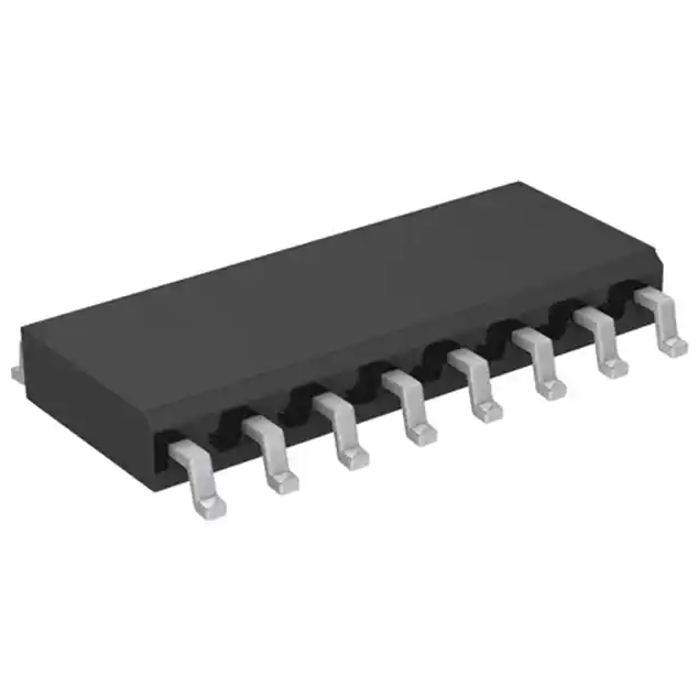
The TF2110M and TF2113M are offered in 16-pin SOIC wide and
14-pin PDIP packages. They operate over an extended -40 °C to
+125 °C temperature range.
Applications
DC-DC Converters
AC-DC Inverters
Motor Controls
Class D Power Amplifiers
Typical Application
Ordering Information
PART NUMBER
TF2110M-3BS
TF2110M-TEU
TF2110M-TEH
TF2113M-3BS
TF2113M-TEU
TF2113M-TEH
www.tfsemi.com
July 2019
PDIP-14
SOIC-16W
PACKAGE
PDIP-14
SOIC-16W
SOIC-16W
PDIP-14
SOIC-16W
SOIC-16W
Year Year Week Week
PACK / Qty
Tube / 25
Tube / 45
T & R / 1500
Tube / 25
Tube / 45
T & R / 1500
MARK
YYWW
TF2110
Lot ID
YYWW
TF2113
Lot ID
Rev. 2.3
1
�TF2110M /2113M
High-Side and Low-Side Gate Drivers
Pin Diagrams
Top View: PDIP-14
TF2110M /TF2113M
Top View : SOIC -16 Wide
TF2110M /TF2113M
Pin Descriptions
PIN NAME
PIN DESCRIPTION
VDD
Logic power supply pin
HIN
Logic input pin for the high-side gate driver output. HIN and HO are in phase
SD
Logic input shutdown pin
LIN
Logic input pin for the low side gate driver output. LIN and LO are in phase
VSS
Logic ground pin
VB
High-side gate driver floating power supply pin
HO
High-side gate driver output pin
VS
High-side gate driver floating power supply return pin
Vcc
Low-side gate driver power supply pin
LO
Low-side gate driver output pin
COM
Low-side gate driver power supply return pin
NC
“No connect” pin
July 2019
2
�TF2110M /2113M
High-Side and Low-Side Gate Drivers
Absolute Maximum Ratings (NOTE1)
A
VB - High side floating supply voltage (TF2110).....-0.3V to +524V
VB - High side floating supply voltage (TF2113).....-0.3V to +624V
VS - High side floating supply offset voltage....VB -24V to VB+0.3V
VHO - High side floating output voltage...............VS-0.3V to VB+0.3V
dVS / dt - Offset supply voltage transient...................................50 V/ns
SOIC-16W Thermal Resistance (NOTE2)
qJC..................................................................................................45 °C/W
qJA ..................................................................................................90 °C/W
VCC - Low side fixed supply voltage...................................-0.3V to +24V
VLO - Low side output voltage..................................-0.3V to VCC +0.3V
VDD - Logic supply voltage............................................-0.3V to VSS+24V
VSS - Logic supply offset voltage........................VCC-24V to VCC+0.3V
VIN - Logic input voltage (HIN, LIN and SD)...VSS-0.3V to VDD+0.3V
PDIP-14 Thermal Resistance (NOTE2)
qJC..................................................................................................35 °C/W
qJA ..................................................................................................75 °C/W
TJ - Junction temperature.............................................................+150 °C
TL - Lead Temperature (soldering, 10 seconds)........................300 °C
TSTG - Storage temerature ..............................................-55 oC to 150 °C
NOTE2 When mounted on a standard JEDEC 2-layer FR-4 board.
PD - Package power dissipation at TA ≤ 25 °C
SOIC-16W..........................................................................................1.25W
PDIP-14.................................................................................................1.6W
NOTE1 Stresses beyond those listed under “Absolute Maximum Ratings” may cause
permanent damage to the device. These are stress ratings only, and functional operation
of the device at these or any other conditions beyond those indicated in the operational
sections of the specifications is not implied. Exposure to absolute maximum rating
conditions for extended periods may affect device reliability.
Recommended Operating Conditions
Symbol
Parameter
VB
High side floating supply absolute voltage
VS
High side floating supply offset voltage
VHO
MIN
TYP
MAX
Unit
VS + 10
VS + 20
V
TF2110
NOTE3
500
V
TF2113
NOTE3
600
V
High side floating output voltage
VS
VB
V
VCC
Low side fixed supply voltage
10
20
V
VLO
Low side output voltage
0
VCC
V
VDD
Logic supply voltage
VSS + 3
VSS + 20
V
VSS
Logic supply offset voltage
-5 (NOTE 4)
5
V
VIN
Logic input voltage (HIN, LIN and SD)
VSS
VDD
V
TA
Ambient temperature
-40
125
°C
NOTE 3 Logic operational for VS =-4V to +500V. Logic state held for VS= -4V to -VBS
NOTE 4 When VDD
很抱歉,暂时无法提供与“TF2113M-TEH”相匹配的价格&库存,您可以联系我们找货
免费人工找货- 国内价格
- 1+6.38400
- 30+6.14400
- 100+5.66400
- 500+5.18400
- 1000+4.94400


 工商网监
湘ICP备2023018690号
工商网监
湘ICP备2023018690号
