SC8835
Dual Low-Voltage H-Bridge IC
Feature
General Description
Dual H-Bridge Motor Driver
- Capable of Driving Two DC Motors or One
Stepper Motor
- Low-MOSFET ON-Resistance:
HS+LS 305 mΩ
1.5 A Maximum Drive Current Per H-Bridge
Configure Bridges Parallel for 3 A Drive Current
Separate Motor and Logic-Supply Pins
- 0V to 11V Motor-Operating Supply-Voltage
- 2V to 7V Logic Supply-Voltage
Flexible PWM or PHASE/ENABLE Interface
Low-Power Sleep Mode With 95nA Maximum
Supply Current
DFN 2mm x 3mm -12L Package
The SC8835 provides an integrated motor driver
solution for cameras, consumer products, toys, and
other low-voltage or battery-powered motion control
applications. The device has two H-bridge drivers, and
drives two DC motors or one stepper motor, as well as
other devices like solenoids. The output driver block
for each consists of N-channel power MOSFETs
configured as an H-bridge to drive the motor winding.
An internal charge pump generates gate drive voltages.
The SC8835 supplies up to 1.5A of output current per
H-bridge and operates on a motor power supply
voltage from 0V to 11V, and a device power supply
voltage of 2V to 7V.
PHASE/ENABLE and IN/IN interfaces are compatible
Applications
Battery-Powered:
- Cameras
- DSLR Lenses
- Consumer Products
- Toys
- Robotics
- Medical Devices
with industry-standard devices.
Internal
shutdown
functions
are
provided
for
overcurrent protection, short circuit protection, under
voltage lockout, and over temperature.
The SC8835 is packaged in a 12-pin DFN package.
Package
The package of SC8835 is DFN 2*3 -12L.
Information furnished by SteadiChips is believed to be accurate and reliable. However, no responsibility is assumed by SteadiChips for its use, or for any infringements of patents or other
rights of third parties which may result from its use. No license is granted by implication or otherwise under any patent or patent rights of SteadiChips
1
Rev.1.2
©2020~2021 SteadiChips Co., Ltd.
�SC8835
Dual Low-Voltage H-Bridge IC
Absolute Maximum Ratings
(If out of these ratings, the filter may be fail or damaged)
Table 1
SYMBOL
VM
PARAMETER
Motor power supply voltage
MIN
-0.3
MAX
12
VCC
Power supply voltage
-0.3
7
V
TA
Operating ambient Temperature Range
-40
125
℃
Storage Temperature
-65
150
℃
MIN
MAX
UNITS
TSTG
UNITS
V
Recommended Operating Conditions
Table 2
SYMBOL
PARAMETER
VCC
Device power supply voltage
2
7
V
VM
Motor power supply voltage
0
11
V
VIN
Logic level input voltage
0
VCC
V
IOUT
H-bridge output current
0
1.5
A
fPWM
Externally applied PWM frequency
0
250
Operating ambient Temperature Range
-40
TA
kHz
85
℃
Thermal Information
Table 3
SYMBOL
PARAMETER
VALUE
UNITS
RJA
Junction-to-ambient thermal resistance
65.3
℃/W
RJC
Junction-to-thermal resistance
45.8
℃/W
2
Rev.1.2
©2020~2021 SteadiChips Co., Ltd.
�SC8835
Dual Low-Voltage H-Bridge IC
Electrical Characteristics
Specifications are at TA=+25℃, VM=5V, VCC=3V (unless otherwise noted)
SYMBOL
IVM
IVMQ
PARAMETER
TEST CONDITIONS
VM operating supply current
VM sleep mode supply current
IVCC
VCC operating supply current
VUVLO
VCC
undervoltage
voltage
VIL
Input low voltage
VIH
Input high voltage
IIL
Input low current
IIH
Input high current
RPD
Pulldown resistance
No PWM, no load
MIN
TYP
194
50 kHz PWM, no load
350
VM=2V, VCC=0V, all inputs 0V
5
VM=5V, VCC=0V, all inputs 0V
10
MAX
lockout
VCC rising
1.5
VCC falling
1.7
95
V
0.3 x VCC
V
V
VIN=0
5
µA
VIN=3.3V
50
µA
100
IOFF
OFF-state leakage current
IOCP
Overcurrent protection trip level
tDEG
Overcurrent de-glitch time
tOCR
Overcurrent
time
tDEAD
Output dead time
tTSD
Thermal shutdown temperature
nA
µA
0.5 x VCC
HS+LS FET on resistance
UNIT
S
µA
372
RDS(ON)
protection
SPEC
KΩ
VCC=3V, VM=3V, IO=800mA,
TJ=25℃
337
400
VCC=5V, VM=5V, IO=800mA,
TJ=25℃
300
360
1.6
retry
150
mΩ
200
nA
3.5
A
1
µs
1
ms
100
ns
160
180
℃
3
Rev.1.2
©2020~2021 SteadiChips Co., Ltd.
�SC8835
Dual Low-Voltage H-Bridge IC
Timing Requirements
TA=+25℃, VM=5V, VCC=3V, RL=20Ω
NO.
MIN
MAX
UNIT
1
t1
Delay time, xPHASE high to xOUT1 low
300
ns
2
t2
Delay time, xPHASE high to xOUT2 high
200
ns
3
t3
Delay time, xPHASE low to xOUT1 high
200
ns
4
t4
Delay time, xPHASE low to xOUT2 low
300
ns
5
t5
Delay time, xENBL low to xOUTx high
200
ns
6
t6
Delay time, xENBL low to xOUTx low
300
ns
7
t7
Output enable time
300
ns
8
t8
Output disable time
300
ns
9
t9
Delay time, xINx high to xOUTx high
160
ns
10
t10
Delay time, xINx low to xOUTx low
160
ns
11
tR
Output rise time
30
188
ns
12
tF
Output fall time
30
188
ns
4
Rev.1.2
©2020~2021 SteadiChips Co., Ltd.
�SC8835
Dual Low-Voltage H-Bridge IC
PHASE/ENBL mode
IN/IN mode
Fig. 1 Timing Requirements
5
Rev.1.2
©2020~2021 SteadiChips Co., Ltd.
�SC8835
Dual Low-Voltage H-Bridge IC
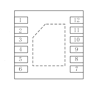
PAD Definition
Top View
Fig 2. Pad definition of SC8835
Table 7. Pad definition
No.
Name
I/O
1
VM
POWER
2
AOUT1
O
Bridge A output 1
3
AOUT2
O
Bridge A output 2
4
BOUT1
O
Bridge B output 1
5
BOUT2
O
Bridge B output 2
6
GND
GROUND
7
8
BIN2/BENBL
BIN1/BPHASE
9
10
AIN2/AENBL
AIN1/APHASE
I
I
I
I
11
MODE
I
12
VCC
POWER
Description
Motor supply
EXTERNAL COMPONENTS OR CONNECTIONS
Bypass to GND with 0.1µF (minimum)
ceramic capacitor
Connect to motor winding A
Connect to motor winding B
Device ground
Bridge B input 2/ENABLE input
IN/IN mode: Logic high sets BOUT2 high
PH/EN mode: Logic high enables H-bridge B
Internal pulldown resistor
Bridge B input 1/PHASE input
IN/IN mode: Logic high sets BOUT1 high
PH/EN mode: Sets direction of H-bridge B
Internal pulldown resistor
Bridge A input 2/ENABLE input
IN/IN mode: Logic high sets AOUT2 high
PH/EN mode: Logic high enables H-bridge A
Internal pulldown resistor
Bridge A input 1/PHASE input
IN/IN mode: Logic high sets AOUT1 high
PH/EN mode: Sets direction of H-bridge A
Internal pulldown resistor
Input mode select
Logic low selects IN/IN mode
Logic high selects PH/EN mode
Internal pulldown resistor
Device supply
Bypass to GND
ceramic capacitor
with
0.1µF(minimum)
6
Rev.1.2
©2020~2021 SteadiChips Co., Ltd.
�SC8835
Dual Low-Voltage H-Bridge IC
Feature Description
The SC8835 is an integrated motor-driver solution used for brushed motor control. The device integrates two
H-bridges, and drives two DC motor or one stepper motor. The output driver block for each H-bridge consists of
N-channel power MOSFETs. An internal charge pump generates the gate drive voltages. Protection features include
overcurrent protection, short circuit protection, undervoltage lockout, and overtemperature protection.
The bridges connect in parallel for additional current capability.
The SC8835 allows separation of the motor voltage and logic voltage if desired. If VM and VCC are less than 7 V, the
two voltages can be connected.
The mode pin allow selection of either a PHASE/ENABLE or IN/IN interface.
Protection Circuits
The SC8835 is fully protected against undervoltage, overcurrent, and overtemperature events.
1) Overcurrent Protection (OCP)
An analog current limit circuit on each FET limits the current through the FET by removing the gate drive. If this
analog current limit persists for longer than the OCP time, all FETs in the H-bridge disable. After approximately 1
ms, the bridge re-enable automatically.
Overcurrent conditions on both high-side and low-side devices; a short to ground, supply, or across the motor
winding result in an overcurrent shutdown.
2) Thermal Shutdown (TSD)
If the die temperature exceeds safe limits, all FETs in the H-bridge disable. Operation automatically resumes once
the die temperature falls to a safe level.
3) Undervoltage Lockout (UVLO)
If at any time the voltage on the VCC pins falls below the undervoltage lockout threshold voltage, all circuitry in
the device disable, and internal logic resets. Operation resumes when VCC rises above the UVLO threshold.
Table 1. Device Protection
FAULT
CONDITION
ERROR REPORT
H-BRIDGE
INTERNAL
CIRCUITS
RECOVERY
VCC undervoltage
(UVLO)
VCC < VUVLO
None
Disabled
Disabled
VCC > VUVLO
Overcurrent (OCP)
IOUT > IOCP
None
Disabled
Operating
tOCR
Thermal Shutdown
(TSD)
TJ > TTSD
None
Disabled
Operating
TJ < TTSD – THYS
7
Rev.1.2
©2020~2021 SteadiChips Co., Ltd.
�SC8835
Dual Low-Voltage H-Bridge IC
1) Bridge Control
Two control modes are available in the SC8835: IN/IN mode, and PHASE/ENABLE mode. IN/IN mode is selected if
the MODE pin is driven low or left unconnected; PHASE/ENABLE mode is selected if the MODE pin is driven to
logic high. Table 3 and Table 4 show the logic for these modes.
Table 3. IN/IN Mode
MODE
xIN1
xIN2
xOUT1
xOUT2
0
0
0
Z
Z
FUNCTION
(DC MOTOR)
Coast
0
0
0
1
1
0
L
H
H
L
Reverse
Forward
0
1
1
L
L
Brake
Table 4. Phase/Enable Mode
FUNCTION
(DC MOTOR)
Brake
MODE
xENABLE
xPHASE
xOUT1
xOUT2
1
0
X
L
L
1
1
1
L
H
Reverse
1
1
0
H
L
Forward
2) Sleep Mode
If the VCC pin reaches 0 V, the SC8835 enters a low-power sleep mode. In this state all unnecessary internal
circuitry powers down. For minimum supply current, all inputs should be low (0 V) during sleep mode.
8
Rev.1.2
©2020~2021 SteadiChips Co., Ltd.
�SC8835
Dual Low-Voltage H-Bridge IC
Application and Implementation
Application Information
The SC8835 is used in one or two motor control applications. Configure the SC8835 in parallel to provide double
the current to one motor. The following design procedure can be used to configure the SC8835 in a brushed motor
application.
Typical Application
The two H-bridges in the SC8835 drivers 1x Stepper motor or 2x DC motor. Figure 2 shows the connections.
Fig.2 Drivers 1x Stepper motor or 2x DC motor
1
VM
GND
6
Thermal Pad
VCC
12
The two H-bridges in the SC8835 connect in parallel for double the current of a single H-bridge. Figure 6 shows the
connections.
Fig.3 Parallel Mode Connections
9
Rev.1.2
©2020~2021 SteadiChips Co., Ltd.
�SC8835
Dual Low-Voltage H-Bridge IC
Package
DFN 2*3-12L
Symbol
Millimeters
MIN
NOM
MAX
A
0.70
0.75
0.80
A1
0
0.02
0.05
b
0.20
0.25
0.30
b1
0.18REF
c
0.203REF
D
2.90
3.00
3.10
D2
1.90
2.00
2.10
E
1.90
2.00
2.10
E2
0.80
0.90
1.00
E3
0.60
0.70
0.80
E4
0.10
0.20
0.30
e
0.50BSC
Nd
2.50BSC
L
0.25
0.30
0.35
R
0.05
0.10
0.15
K
0.25REF
10
Rev.1.2
©2020~2021 SteadiChips Co., Ltd.
�


 工商网监
湘ICP备2023018690号
工商网监
湘ICP备2023018690号
