Product Overview
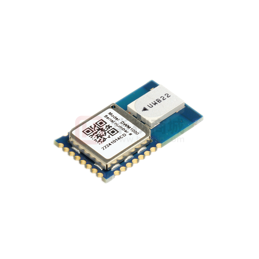
The DWM1000 module is based on Decawave's DW1000 Ultra
Wideband (UWB) transceiver IC. It integrates antenna, all RF
circuitry, power management and clock circuitry in one module.
It can be used in 2-way ranging or TDOA location systems to
locate assets to a precision of 10 cm and supports data rates of
up to 6.8 Mbps
•
•
•
•
•
•
•
•
•
•
•
•
•
IEEE 802.15.4-2011 UWB
compliant
Supports 4 RF bands from
3.5 GHz to 6.5 GHz
Programmable transmitter
output power
Fully coherent receiver for
maximum range and accuracy
Designed to comply with FCC
& ETSI UWB spectral masks
Supply voltage 2.8 V to 3.6 V
Low power consumption
Data rates of 110 kbps,
850 kbps, 6.8 Mbps
Maximum packet length of
1023 bytes for high data
throughput applications
Integrated MAC support
features
Supports 2-way ranging and
TDOA
SPI interface to host processor
23 mm x 13 mm x 2.9 mm 24pin side castellation package
•
•
•
•
•
•
Simplifies integration, no RF design
required
Very precise location of tagged objects
delivers enterprise efficiency gains and
cost reductions
Extended communications range
minimises required infrastructure in
RTLS
High multipath fading immunity
Supports very high tag densities in
RTLS
Low cost allows cost-effective
implementation of solutions
Low power consumption reduces the
need to replace batteries and lowers
system lifetime costs
Applications
•
•
Precision real time location systems
(RTLS) using two-way ranging or
TDOA schemes in a variety of
markets.
Location aware wireless sensor
networks (WSNs)
On-board
Power
Management
On-board
Antenna
ANALOG RECEIVER
PLL / CLOCK GENERATOR
ANALOG TRANSMITTER
POWER MANAGEMENT
DIGITAL TRANSCEIVER
•
Key Benefits
HOST INTERFACE / SPI
STATE CONTROLLER
DW1000 IC
DWM1000
High Level Block Diagram
DC/DC
SPI I/F
On-board
Crystal and
Clock
Management
2.8 V to
3.6 V DC
supply
SPI Control
Interface
DWM1000 IEEE 802.15.4-2011 UWB Transceiver Module
Key Features
�DWM1000 Datasheet
Table of Contents
1
OVERVIEW ................................................... 5
1.1 DWM1000 FUNCTIONAL DESCRIPTION ........... 5
1.2 DWM1000 POWER UP ............................... 5
1.3 SPI HOST INTERFACE .................................... 6
1.3.1
SPI Signal Timing .............................. 6
1.4 GENERAL PURPOSE INPUT OUTPUT (GPIO) ...... 7
1.5 ALWAYS-ON (AON) MEMORY ....................... 7
1.6 ONE-TIME PROGRAMMABLE (OTP) MEMORY ... 7
1.7 INTERRUPTS AND DEVICE STATUS .................... 7
1.8 MAC ......................................................... 7
2
Crystal Oscillator Trim ...................... 8
Transmitter Calibration .................... 8
Antenna Delay Calibration ............... 8
5
7
ELECTRICAL SPECIFICATIONS ...................... 12
APPLICATION INFORMATION ..................... 17
5.1
ORDERING INFORMATION .......................... 24
7.1 TAPE AND REEL INFORMATION FOR DWM1000
V1
24
7.2 TAPE AND REEL INFORMATION FOR DWM1000
V2
26
7.3 DWM1000 PACKAGING INFORMATION ......... 27
7.3.1
Inner Box V2.................................... 27
7.3.2
Outer Box V2 ................................... 27
PIN NUMBERING .......................................... 9
PIN DESCRIPTIONS ........................................ 9
4.1 NOMINAL OPERATING CONDITIONS ............... 12
4.2 DC CHARACTERISTICS.................................. 12
4.3 RECEIVER AC CHARACTERISTICS .................... 12
4.4 RECEIVER SENSITIVITY CHARACTERISTICS ......... 13
4.5 REFERENCE CLOCK AC CHARACTERISTICS ........ 13
4.5.1
Reference Frequency ...................... 13
4.6 TRANSMITTER AC CHARACTERISTICS .............. 13
4.7 TEMPERATURE AND VOLTAGE MONITOR
CHARACTERISTICS.................................................. 14
4.8 ANTENNA PERFORMANCE ............................ 14
4.9 ABSOLUTE MAXIMUM RATINGS .................... 16
PACKAGE INFORMATION ............................ 20
6.1 MODULE DRAWINGS ................................... 20
6.2 MODULE LAND PATTERN ............................. 20
6.3 DWM1000 V1 MODULE MARKING
INFORMATION ...................................................... 22
6.4 DWM1000 V2 MODULE MARKING
INFORMATION ...................................................... 22
6.5 MODULE SOLDER PROFILE ............................ 23
DWM1000 PIN CONNECTIONS ..................... 9
3.1
3.2
4
6
DWM1000 CALIBRATION ............................. 8
2.1.1
2.1.2
2.1.3
3
5.2 APPLICATION CIRCUIT DIAGRAM .................... 17
5.2.1
SPI Bus ............................................ 18
5.2.2
Configuring the SPI Mode ............... 18
5.2.3
Powering down the DWM1000 ...... 19
8
REGULATORY INFORMATION...................... 28
8.1 EUROPEAN UNION REQUIREMENTS ................ 28
8.1.1
Radio Equipment Directive ............. 28
8.1.2
ETSI harmonised standards ........... 29
9
GLOSSARY ................................................... 30
10
REFERENCES ............................................ 31
11
DOCUMENT HISTORY .............................. 31
12
FURTHER INFORMATION ......................... 33
APPLICATION BOARD LAYOUT GUIDELINES ...... 17
List of Figures
FIGURE 1: DWM1000 POWER-UP SEQUENCE ................ 5
FIGURE 2: DW1000 SPIPHA=0 TRANSFER PROTOCOL.... 6
FIGURE 3: DWM1000 SPI TIMING DIAGRAM ................ 6
FIGURE 4: DWM1000 SPI DETAILED TIMING DIAGRAM .. 6
FIGURE 5: DWM1000 PIN DIAGRAM ........................... 9
FIGURE 6. DWM1000 CIRCUIT BOARD MOUNTING....... 14
FIGURE 7. MEASURED ANTENNA RADIATION PATTERNS... 15
FIGURE 8: DWM1000 APPLICATION BOARD KEEP-OUT
AREAS ............................................................. 17
FIGURE 9: EXAMPLE DWM1000 APPLICATION CIRCUIT .. 18
FIGURE 10: SPI BUS CONNECTIONS ............................ 18
FIGURE 11: MODULE PACKAGE SIZE (UNITS: MM) ......... 20
FIGURE 12: DWM1000 MODULE LAND PATTERN (UNITS:
MM) ............................................................... 21
FIGURE 13: DWM1000 V1 MODULE MARKING
© Decawave Ltd 2016
INFORMATION ................................................... 22
FIGURE 14: DWM1000 V2 MODULE MARKING
INFORMATION ................................................... 22
FIGURE 15: DWM1000 MODULE SOLDER PROFILE ....... 23
FIGURE 16: DWM1000 V1 MODULE CARRIER DIMENSION
(UNITS: MM)..................................................... 24
FIGURE 17: DWM1000 V1 MODULE TAPE CARRIER
DIMENSION (UNITS: MM) .................................... 25
FIGURE 16: DWM1000 V2 MODULE CARRIER DIMENSION
(UNITS: MM)..................................................... 26
FIGURE 17: DWM1000 V2 MODULE TAPE CARRIER
DIMENSION (UNITS: MM) .................................... 26
FIGURE 18: MODULE INNER BOX (UNITS: MM) .............. 27
FIGURE 19: MODULE OUTER BOX: (MODULE QUANTITY
2000 PIECES) ................................................... 27
Subject to change without notice
Version 1.8
Page 2
�DWM1000 Datasheet
List of Tables
TABLE 1: DW1000 POWER-UP TIMINGS ........................ 5
TABLE 2: DWM1000 SPI TIMING PARAMETERS ............. 6
TABLE 3: DWM1000 PIN FUNCTIONS ........................... 9
TABLE 4: EXPLANATION OF ABBREVIATIONS ................... 11
TABLE 5: DWM1000 OPERATING CONDITIONS ............ 12
TABLE 6: DWM1000 DC CHARACTERISTICS ................. 12
TABLE 7: DWM1000 RECEIVER AC CHARACTERISTICS ... 12
TABLE 8: DWM1000 TYPICAL RECEIVER SENSITIVITY
CHARACTERISTICS .............................................. 13
TABLE 9: DWM1000 REFERENCE CLOCK AC
CHARACTERISTICS .............................................. 13
TABLE 10: DWM1000 TRANSMITTER AC CHARACTERISTICS
...................................................................... 13
TABLE 11: DWM1000 TEMPERATURE AND VOLTAGE
MONITOR CHARACTERISTICS................................ 14
TABLE 12: DWM1000 ABSOLUTE MAXIMUM RATINGS . 16
TABLE 13: DW1000 SPI MODE CONFIGURATION ......... 18
TABLE 14: MODULE WEIGHT ...................................... 21
TABLE 15: GLOSSARY OF TERMS .................................. 30
© Decawave Ltd 2016
Subject to change without notice
Version 1.8
Page 3
�DWM1000 Datasheet
DOCUMENT INFORMATION
Disclaimer
Decawave reserves the right to change product specifications without notice. As far as possible changes to
functionality and specifications will be issued in product specific errata sheets or in new versions of this
document. Customers are advised to check with Decawave for the most recent updates on this product.
Copyright © 2016 Decawave Ltd
LIFE SUPPORT POLICY
Decawave products are not authorized for use in safety-critical applications (such as life support) where a
failure of the Decawave product would reasonably be expected to cause severe personal injury or death.
Decawave customers using or selling Decawave products in such a manner do so entirely at their own risk
and agree to fully indemnify Decawave and its representatives against any damages arising out of the use of
Decawave products in such safety-critical applications.
Caution! ESD sensitive device. Precaution should be used when handling the device in order
to prevent permanent damage.
REGULATORY APPROVALS
The DWM1000, as supplied from Decawave, has not been certified for use in any particular geographic
region by the appropriate regulatory body governing radio emissions in that region although it is
capable of such certification depending on the region and the manner in which it is used.
All products developed by the user incorporating the DWM1000 must be approved by the relevant
authority governing radio emissions in any given jurisdiction prior to the marketing or sale of such
products in that jurisdiction and user bears all responsibility for obtaining such approval as needed
from the appropriate authorities.
© Decawave Ltd 2016
Version 1.8
Page 4
�DWM1000 Datasheet
1 OVERVIEW
The DWM1000 module is an IEEE 802.15.4-2011 UWB implementation. RF components, Decawave DW1000
UWB transceiver, and other components reside on-module. DWM1000 enables cost effective and reduced
complexity integration of UWB communications and ranging features, greatly accelerating design implementation.
1.1
DWM1000 Functional Description
The DW1000 on board the DWM1000 is a fully integrated low-power, single chip CMOS RF transceiver IC
compliant with the IEEE 802.15.4-2011 [1] UWB standard. The DWM1000 module requires no RF design as the
antenna and associated analog and RF components are on the module.
The module contains an on-board 38.4 MHz reference crystal. The crystal has been trimmed in production to
reduce the initial frequency error to approximately 2 ppm, using the DW1000 IC’s internal on-chip crystal trimming
circuit, see section 2.1.1.
Always-On (AON) memory can be used to retain DWM1000 configuration data during the lowest power operational
states when the on-chip voltage regulators are disabled. This data is uploaded and downloaded automatically. Use
of DWM1000 AON memory is configurable.
The on-chip voltage and temperature monitors allow the host to read the voltage on the VDDAON pin and the
internal die temperature information from the DW1000.
See the DW1000 Datasheet [2] for more detailed information on device functionality, electrical specifications and
typical performance.
1.2
DWM1000 Power Up
3.3 V Supplies
Von
(VDDAON / VDD / VDD)
EXTON
Text_on
RSTn
Tdig_on
STATE
OFF
POWER UP
INIT
Figure 1: DWM1000 Power-up Sequence
When power is applied to the DWM1000, RSTn is driven low by internal circuitry as part of its power up
sequence. See Figure 1 above. RSTn remains low until the on-module crystal oscillator has powered up and its
output is suitable for use by the rest of the device, at which time RSTn is deasserted high.
Table 1: DW1000 Power-up Timings
Parameter
Description
Nominal
Value
Units
2.0
V
VON
Voltage threshold to enable power up
TEXT_ON
Time at which EXTON goes high before RSTn is
released
3
ms
TDIG_ON
RSTn held low by internal reset circuit / driven low by
external reset circuit
3
ms
RSTn may be used as an output to reset external circuitry as part of system bring-up as power is applied.
An external circuit can reset the DWM1000 by asserting RSTn for a minimum of 10 ns. RSTn is an
asynchronous input. DW1000 initialization will proceed when the pin is released to high impedance. RSTn
should never be driven high by an external source.
© Decawave Ltd 2016
Version 1.8
Page 5
�DWM1000 Datasheet
Please see DW1000 Datasheet [2] for more details of DW1000 power up.
1.3
SPI Host Interface
The DW1000 host communications interface is a slave-only SPI. Both clock polarities (SPIPOL=0/1) and phases
(SPIPHA=0/1) are supported. The data transfer protocol supports single and multiple byte read/writes accesses.
All bytes are transferred MSB first and LSB last. A transfer is initiated by asserting SPICSn low and terminated
when SPICSn is deasserted high.
See the DW1000 Datasheet [2] for full details of the SPI interface operation and mode configuration for clock
phase and polarity.
Cycle
Number, #
1
2
3
4
5
6
7
8
8*Number of
bytes
9
SPIPOL=0, SPIPHA=0
SPICLK
SPIPOL=1, SPIPHA=0
SPICLK
SPICSn
SPIMISO
z
MSB
6
5
4
3
2
1
LSB
MSB
LSB
X
Z
SPIMOSI
z
MSB
6
5
4
3
2
1
LSB
MSB
LSB
X
Z
Figure 2: DW1000 SPIPHA=0 Transfer Protocol
1.3.1
SPI Signal Timing
SPICSn
S PICLK
Bit 7 Bit 6 Bit 5 Bit 4 Bit 3 Bit 2 Bit 1 Bit 0
SPIMOSI
7
SPIMISO
6
5
4
3
2
1
Bit 7 Bit 6 Bit 5 Bit 4 Bit 3 Bit 2 Bit 1 Bit 0
0
t7
7
6
5
4
3
2
1
Bit 7 Bit 6 Bit 5
0
7
t5
t8
6
5
t6
t9
Figure 3: DWM1000 SPI Timing Diagram
SPICSn
S PICLK
Bit 7
SPIMOSI
Bit 6
7
SPIMISO
t3
t1
Bit 5
6
t4
5
t2
Figure 4: DWM1000 SPI Detailed Timing Diagram
Table 2: DWM1000 SPI Timing Parameters
Parameter
SPICLK
Period
Min
Max
50
t1
t2
Typ
38
12
© Decawave Ltd 2016
Unit
Description
ns
The maximum SPI frequency is 20 MHz when the CLKPLL is locked,
otherwise the maximum SPI frequency is 3 MHz.
ns
SPICSn select asserted low to valid slave output data
ns
SPICLK low to valid slave output data
Version 1.8
Page 6
�DWM1000 Datasheet
Parameter
Min
t3
10
ns
Master data setup time
t4
10
ns
Master data hold time
t5
32
ns
LSB last byte to MSB next byte
ns
SPICSn de-asserted high to SPIMISO tri-state
t6
1.4
Typ
Max
10
Unit
Description
t7
16
ns
Start time; time from select asserted to first SPICLK
t8
40
ns
Idle time between consecutive accesses
t9
40
ns
Last SPICLK to SPICSn de-asserted
General Purpose Input Output (GPIO)
The DWM1000 provides 8 configurable pins.
On reset, all GPIO pins default to input. GPIO inputs, when appropriately configured, are capable of generating
interrupts to the host processor via the IRQ signal.
GPIO0, 1, 2, & 3, as one of their optional functions, can drive LEDs to indicate the status of various chip
operations. Any GPIO line being used to drive an LED in this way should be connected as shown. GPIO5 & 6
are used to configure the operating mode of the SPI as described in the DW1000 Datasheet [2].
See DW1000 Datasheet [2] and DW1000 User Manual [3] provide full details of the configuration and use of the
GPIO lines.
1.5
Always-On (AON) Memory
Configuration retention in lowest power states is enabled in DWM1000 by provision of an Always-On (AON)
memory array with a separate power supply, VDDAON. The DWM1000 may be configured to upload its
configuration to AON before entering a low-power state and to download the configuration when waking up from
the low –power state.
1.6
One-Time Programmable (OTP) Memory
The DWM1000 contains a 56x32 -bit user programmable OTP memory on the DW1000 device that is used to
store per chip calibration information.
1.7
Interrupts and Device Status
DWM1000 has a number of interrupt events that can be configured to drive the IRQ output pin. The default IRQ
pin polarity is active high. A number of status registers are provided in the system to monitor and report data of
interest. See DW1000 User Manual [3] for a full description of system interrupts and their configuration and of
status registers.
1.8
MAC
A number of MAC features are implemented including CRC generation, CRC checking and receive frame filtering.
See the DW1000 Datasheet [2] and DW1000 User Manual [3] for full details.
© Decawave Ltd 2016
Version 1.8
Page 7
�DWM1000 Datasheet
2 DWM1000 CALIBRATION
Depending on the end-use application s and the system design, DWM1000 settings may need to be tuned. To
help with this tuning a number of built in functions such as continuous wave TX and continuous packet
transmission can be enabled. See the DW1000 User Manual [3] for further details.
2.1.1
Crystal Oscillator Trim
DWM1000 modules are calibrated at production to minimise initial frequency error to reduce carrier frequency
offset between modules and thus improve receiver sensitivity. The calibration carried out at module production
will trim the initial frequency offset to less than 2 ppm, typically.
2.1.2
Transmitter Calibration
In order to maximise range, DWM1000 transmit power spectral density (PSD) should be set to the maximum
allowable for the geographic region in which it will be used. For most regions this is -41.3 dBm/MHz.
As the module contains an integrated antenna, the transmit power can only be measured over the air. The
Effective Isotropic Radiated Power (EIRP) must be measured and the power level adjusted to ensure compliance
with applicable regulations.
The DWM1000 provides the facility to adjust the transmit power in coarse and fine steps; 3 dB and 0.5 dB
nominally. It also provides the ability to adjust the spectral bandwidth. These adjustments can be used to
maximise transmit power whilst meeting regulatory spectral mask.
If required, transmit calibration should be carried out on a per DWM1000 module basis, see DW1000 User
Manual [3] for full details. 1
2.1.3
Antenna Delay Calibration
In order to measure range accurately, precise calculation of timestamps is required. To do this the antenna delay
must be known. The DWM1000 allows this delay to be calibrated and provides the facility to compensate for
delays introduced by PCB, external components, antenna and internal DWM1000 delays.
To calibrate the antenna delay, range is measured at a known distance using two DWM1000 systems. Antenna
delay is adjusted until the known distance and reported range agree. The antenna delay can be stored in OTP
memory.
Antenna delay calibration must be carried out as a once off measurement for each DWM1000 design
implementation. If required, for greater accuracy, antenna delay calibration should be carried out on a per
DWM1000 module basis, see DW1000 User Manual [3] for full details.
1To achieve best results when using the DWM1000 with Decawave’s DecaRanging software, you will need to
adjust the default transmit power value programmed into the DWM1000 by the software. This is because
DecaRanging software is targeted at Decawave’s EVB1000 evaluation board which has a different RF path
compared to the DWM1000. You should increase the transmit power by approximately 3 dB.
© Decawave Ltd 2016
Version 1.8
Page 8
�DWM1000 Datasheet
3 DWM1000 PIN CONNECTIONS
3.1
Pin Numbering
DWM1000 module pin assignments are as follows (viewed from top): -
UWB
Chip
Antenna
22 IRQ / GPIO8
GPIO7
4
21 VSS
VDDAON
5
20 SPICLK
VDD3V3
6
19 SPIMISO
VDD3V3
7
18 SPIMOSI
VSS
8
17 SPICSn
GPIO6 / EXTRXE / SPIPHA
VSS 16
3
GPIO0 / RXOKLED 15
RSTn
GPIO1 / SFDLED 14
23 VSS
GPIO2 / RXLED 13
2
GPIO3 / TXLED 12
WAKEUP
GPIO4 / EXTPA 11
24 VSS
GPIO5 / EXTTXE / SPIPOL 10
1
9
EXTON
Figure 5: DWM1000 Pin Diagram
3.2
Pin Descriptions
Table 3: DWM1000 Pin functions
SIGNAL NAME
PIN
I/O
(Default)
DESCRIPTION
Digital Interface
SPICLK
20
DI
SPIMISO
19
DO
(O–L)
SPIMOSI
18
DI
SPI data input. Refer to DW1000 Datasheet for more details [2].
DI
SPI chip select. This is an active low enable input. The high-to-low
transition on SPICSn signals the start of a new SPI transaction.
SPICSn can also act as a wake-up signal to bring DW1000 out of
either SLEEP or DEEPSLEEP states Refer to DW1000 Datasheet
for more details [2].
DIO
When asserted into its active high state, the WAKEUP pin brings
the DW1000 out of SLEEP or DEEPSLEEP states into operational
mode.
If unused, this pin can be tied to ground.
SPICSn
WAKEUP
© Decawave Ltd 2016
17
2
SPI clock
SPI data output. Refer to DW1000 Datasheet for more details [2].
Version 1.8
Page 9
�DWM1000 Datasheet
SIGNAL NAME
EXTON
IRQ / GPIO8
GPIO7
GPIO6 /
SPIPHA
I/O
(Default)
DESCRIPTION
DO
(O-L)
External device enable. Asserted during wake up process and held
active until device enters sleep mode. Can be used to control
external DC-DC converters or other circuits that are not required
when the device is in sleep mode so as to minimize power
consumption. Refer to DW1000 Datasheet for more details [2].
22
DIO
(O-L)
Interrupt Request output from the DWM1000 to the host processor.
By default IRQ is an active-high output but may be configured to be
active low if required. For correct operation in SLEEP and
DEEPSLEEP modes it should be configured for active high
operation. This pin will float in SLEEP and DEEPSLEEP states and
may cause spurious interrupts unless pulled low.
When the IRQ functionality is not being used the pin may be
reconfigured as a general purpose I/O line, GPIO8.
4
DIO
(I)
Defaults to operate as a SYNC input – refer [2]. THIS
FUNCTIONALITY IS NOT APPLICABLE TO THE DWM1000. This
pin may be reconfigured as a general purpose I/O pin, GPIO7 under
software control.
DIO
(I)
General purpose I/O pin.
On power-up it acts as the SPIPHA (SPI phase selection) pin for
configuring the SPI mode of operation. Refer to Section 5.2.2 and
the DW1000 Datasheet for more details [2].
After power-up, the pin will default to a General Purpose I/O pin.
PIN
1
9
GPIO5 /
SPIPOL
10
DIO
(I)
General purpose I/O pin.
On power-up it acts as the SPIPOL (SPI polarity selection) pin for
configuring the SPI operation mode. Refer to Section 5.2.2 and the
DW1000 Datasheet for more details [2].
After power-up, the pin will default to a General Purpose I/O pin.
GPIO4
11
DIO
(I)
General purpose I/O pin.
12
DIO
(I)
General purpose I/O pin.
It may be configured for use as a TXLED driving pin that can be
used to light a LED following a transmission. Refer to the DW1000
User Manual [2] for details of LED use.
13
DIO
(I)
General purpose I/O pin.
It may be configured for use as a RXLED driving pin that can be
used to light a LED during receive mode. Refer to the DW1000
User Manual [2] for details of LED use.
14
DIO
(I)
General purpose I/O pin.
It may be configured for use as a SFDLED driving pin that can be
used to light a LED when SFD (Start Frame Delimiter) is found by
the receiver. Refer to the DW1000 User Manual [2] for details of
LED use.
GPIO0 /
RXOKLED
15
DIO
(I)
General purpose I/O pin.
It may be configured for use as a RXOKLED driving pin that can be
used to light a LED on reception of a good frame. Refer to the
DW1000 User Manual [2] for details of LED use.
RSTn
3
DIO
(O-H)
GPIO3 / TXLED
GPIO2 / RXLED
GPIO1 /
SFDLED
Reset pin. Active Low Output.
May be pulled low by external open drain driver to reset the
DW1000. Refer to DW1000 Datasheet for more details [2].
Power Supplies
VDDAON
5
P
External supply for the Always-On (AON) portion of the chip.
VDD3V3
6,7
P
3.3 V supply pins. Note that for programming the OTP in the
DWM1000 module this voltage may be increased to a nominal value
of 3.8 V for short periods.
© Decawave Ltd 2016
Version 1.8
Page 10
�DWM1000 Datasheet
SIGNAL NAME
PIN
I/O
(Default)
DESCRIPTION
Ground
GND
8,16,
21,23,24
G
Common ground.
Table 4: Explanation of Abbreviations
ABBREVIATION
I
EXPLANATION
Input
IO
Input / Output
O
Output
G
Ground
P
Power Supply
PD
Power Decoupling
O-L
Defaults to output, low level after reset
O-H
Defaults to output, high level after reset
I
Defaults to input.
Note: Any signal with the suffix ‘n’ indicates an active low signal.
© Decawave Ltd 2016
Version 1.8
Page 11
�DWM1000 Datasheet
4 ELECTRICAL SPECIFICATIONS
4.1
Nominal Operating Conditions
Table 5: DWM1000 Operating Conditions
Parameter
Min.
Operating temperature
-40
Supply voltage VDDAON, VDD3V3
2.8
Supply voltage VDD3V3 for programming
OTP
Typ.
3.3
3.7
3.8
Voltage on GPIO0..7, WAKEUP, RSTn,
SPICSn, SPIMOSI, SPICLK
Max.
Units
Condition/Note
+85
˚C
3.6
V
Normal operation
3.9
V
Note that for programming the
OTP in the DWM1000 the
VDD3V3 voltage must be
increased to 3.8 V nominal for
short periods.
3.6
V
Note that 3.6 V is the max
voltage that may be applied to
these pins
Note: Unit operation is guaranteed by design when operating within these ranges
4.2
DC Characteristics
Tamb = 25 ˚C, all supplies centred on typical values
Table 6: DWM1000 DC Characteristics
Parameter
Min.
Supply current DEEP SLEEP mode
Typ.
Max.
200
Units
nA
Supply current SLEEP mode
550
nA
Supply current IDLE mode
13.4
mA
Supply current INIT mode
3.5
mA
TX : 3.3 V supplies
(VDDAON, VDD)
RX : 3.3 V supplies
(VDDAON, VDD)
Digital input voltage high
4.3
mA
Channel 5:TX Power:
9.3 dBm/500 MHz
160
mA
Channel 5
0.3*VDD
V
V
Assumes 500 Ω load
0.3*VDD
V
Assumes 500 Ω load
V
0.7*VDD
Digital output voltage low
Digital Output Drive Current
GPIOx, IRQ
SPIMISO
EXTON
4
8
3
Total current drawn from all
supplies.
140
0.7*VDD
Digital input voltage low
Digital output voltage high
Condition/Note
6
10
4
mA
Receiver AC Characteristics
Tamb = 25 ˚C, all supplies centred on nominal values
Table 7: DWM1000 Receiver AC Characteristics
Parameter
Frequency range
Min.
Typ.
3244
Max.
Units
6999
MHz
Condition/Note
Channel bandwidth
500
MHz
Channel 1,2,3 and 5
In-band blocking level
30
dBc
Continuous wave interferer
Out-of-band blocking level
55
dBc
Continuous wave interferer
© Decawave Ltd 2016
Version 1.8
Page 12
�DWM1000 Datasheet
4.4
Receiver Sensitivity Characteristics
Tamb = 25 ˚C, all supplies centred on typical values. 20 byte payload. These sensitivity figures assume an
antenna gain of 0 dBi and should be modified by the antenna characteristics quoted in Table 12 depending on
the orientation of the DWM1000.
Table 8: DWM1000 Typical Receiver Sensitivity Characteristics
Packet
Error
Rate
1%
10%
4.5
Receiver
Sensitivity
Data Rate
Units
Condition/Note
110 kbps
-102
dBm/500 MHz
Preamble 2048
850 kbps
-101
dBm/500 MHz
Preamble 1024
6.8 Mbps
-93
dBm/500 MHz
Preamble 256
110 kbps
-106
dBm/500 MHz
Preamble 2048
850 kbps
-102
dBm/500 MHz
Preamble 1024
6.8 Mbps
-94
dBm/500 MHz
Preamble 256
All measurements
performed on
Channel 5, PRF 16
MHz
Channel 2 is
approximately 1
dB less sensitive
Carrier
frequency
offset
±10 ppm
Reference Clock AC Characteristics
Tamb = 25 ˚C, all supplies centred on typical values
4.5.1
Reference Frequency
Table 9: DWM1000 Reference Clock AC Characteristics
Parameter
Min.
Typ.
Max.
Units
Condition/Note
On-board crystal oscillator reference
frequency
38.4
MHz
On-board crystal trimming range
±25
ppm
Internally trimmed to +/- 2 ppm
under typical conditions.
±30*
ppm
ppm
-40⁰C to +85⁰
±3
ppm/3year
@25⁰C ±2⁰C
15
kHz
On-board crystal frequency stability
with temperature
On-board crystal aging
Low Power RC Oscillator
5
12
*By using the temperature monitoring capability of the DW1000 chip on the DWM1000 module it is possible to dynamically trim
the crystal during run time to maintain the +/- 2ppm specification over the full temperature range of operation.
4.6
Transmitter AC Characteristics
Tamb = 25 ˚C, all supplies centred on typical values
Table 10: DWM1000 Transmitter AC Characteristics
Parameter
Frequency range
Min.
Typ.
3244
Max.
Units
6999
MHz
Channel Bandwidths
500
Output power spectral density
(programmable)
-39
Power level range
37
dB
Coarse Power level step
3
dB
Fine Power level step
0.5
dB
Output power variation with
temperature
0.05
dB/OC
Output power variation with voltage
2.73
3.34
dB/V
© Decawave Ltd 2016
MHz
-35
dBm/MHz
Condition/Note
Channel 1, 2, 3 and 5
See DW1000 Datasheet [2]
Channel 2
Channel 5
Version 1.8
Page 13
�DWM1000 Datasheet
4.7
Temperature and Voltage Monitor Characteristics
Table 11: DWM1000 Temperature and Voltage Monitor Characteristics
Parameter
Min.
Voltage Monitor Range
Typ.
2.4
Max.
Units
3.75
V
Voltage Monitor Precision
20
mV
Voltage Monitor Accuracy
140
mV
Temperature Monitor Range
-40
Temperature Monitor Precision
4.8
+100
0.9
Condition/Note
°C
°C
Antenna Performance
The antenna used in the module is the Partron dielectric chip antenna, part number ACS5200HFAUWB, see [4]
for full details.
Antenna radiation patterns, measured in an anechoic chamber for three planes, are shown in Figure 7. As the
antenna is linearly polarised, in the Azimuth plane the vertically polarised field (Theta) is measured and the
horizontally polarised field (Phi) is measured for elevation planes 1 and 2.
For these measurements, the DWM1000 module is mounted on a circuit board with dimensions shown in Figure
6.
2.85 cm
2.85 cm
7 cm
7 cm
Figure 6. DWM1000 Circuit Board Mounting
© Decawave Ltd 2016
Version 1.8
Page 14
�DWM1000 Datasheet
Gain (dBi) vs Angle (°)
320
310
Measurement
Plane
180°
330
340
270°
10
5
0
-5
-10
-15
-20
-25
-30
300
290
90°
0
350 10
280
270
20
30
40
50
60
70
80
90
260
0°
DUT rotated
through 360° in
this direction
100
250
110
240
120
230
220
210
200
190
180
170
160
150
130
140
Ch_5
Ch_2
Azimuth Plane (Theta)
Gain (dBi) vs Angle (°)
320
310
330
340
300
180°
290
280
90°
270°
270
0
350 10
10
5
0
-5
-10
-15
-20
-25
-30
20
30
40
50
60
70
80
90
260
100
250
110
240
0°
120
230
220
210
200
190
180
170
160
150
130
140
Ch_5
Ch_2
Elevation 1 Plane (Phi)
Gain (dBi) vs Angle (°)
320
180°
330
340
310
300
90°
270°
290
280
270
0°
350 10
0
10
5
0
-5
-10
-15
-20
-25
-30
20
30
40
50
60
70
80
90
100
260
110
250
120
240
130
230
220
210
200
190
180
170
160
150
140
Ch_5
Ch_2
Elevation 2 Plane (Phi)
Figure 7. Measured Antenna Radiation Patterns
© Decawave Ltd 2016
Version 1.8
Page 15
�DWM1000 Datasheet
4.9
Absolute Maximum Ratings
Table 12: DWM1000 Absolute Maximum Ratings
Parameter
Voltage
VDD3V3 / VDDAON
Min.
Max.
Units
-0.3
4.0
V
0
dBm
Receiver Power
Temperature - Storage temperature
-40
+85
˚C
Temperature – Operating temperature
-40
+85
˚C
2000
V
ESD (Human Body Model)
Stresses beyond those listed in this table may cause permanent damage to the device. This is a stress rating
only; functional operation of the device at these or any other conditions beyond those indicated in the operating
conditions of the specification is not implied. Exposure to the absolute maximum rating conditions for extended
periods may affect device reliability.
© Decawave Ltd 2016
Version 1.8
Page 16
�DWM1000 Datasheet
5 APPLICATION INFORMATION
5.1
Application Board Layout Guidelines
When designing the PCB onto which DWM1000 will be soldered, the proximity of the DWM100 on-board ceramic
monopole antenna to metal and other non-RF transparent materials needs to considered carefully. Two
suggested placement schemes are shown below.
For best RF performance, ground copper should be flooded in all areas of the application board, except
in the areas marked “Keep-Out Area”, where there should be no metal either side, above or below (e.g.
do not place battery under antenna).
The placement schemes in Figure 8 show an application board with no non-RF transparent material in the keepout area, or an application board with the antenna projecting off of the board so that the keep out area is in freespace. In this second scheme it is still important not to place metal components above or below the antenna in a
system implementation. It is also important to note that the ground plane on the application board affects the
DWM1000 antenna radiation pattern. In Figure 8 below, d must be a minimum of 10 mm. This gives the most
vertically polarized radiation pattern. As d is increased from 10 mm the degree of vertical polarization reduces.
d
d
KeepOut Area
KeepOut Area
Antenna
Antenna
d
d
DWM1000
DWM1000
Application Board
Application Board
Figure 8: DWM1000 Application Board Keep-Out Areas
5.2
Application Circuit Diagram
A simple application circuit integrating the DWM1000 module need only power the device and connect the device
to a host controller, see Figure 9.
UWB
Chip
Antenna
DWM1000_RSTn
2
RSTn
3
GPIO7
4
VDDAON
5
VDD3V3
6
19 SPIMISO
VDD3V3
7
18 SPIMOSI
VSS
8
17 SPICSn
DWM1000
22 IRQ / GPIO8
21 VSS
GND
Optional pulldown on
IRQ to prevent
spurious interrupts
Host
uProcessor
VSS 16
GPIO1 / SFDLED 14
20 SPICLK
GPIO0 / RXOKLED 15
GPIO3 / TXLED 12
GPIO6 / EXTRXE / SPIPHA
© Decawave Ltd 2016
23 VSS
Metal Cap
9
GND
WAKEUP
GPIO2 / RXLED 13
0.1uF
+3.3 V
1
GPIO4 / EXTPA 11
Do not do this!
RSTn must never
be pulled high by
an external source
DWM1000_RSTn
24 VSS
EXTON
GPIO5 / EXTTXE / SPIPOL 10
+3.3 V
GND
Version 1.8
Page 17
�DWM1000 Datasheet
Figure 9: Example DWM1000 Application Circuit
5.2.1
SPI Bus
The SPI signal bus and mode configuration pins may need to be treated carefully if it is desirable to connect
additional SPI devices to the SPI bus, or to configure the SPI for a non-default clock polarity of phase behaviour.
Please see the DW1000 Datasheet [2] for a description of all SPI clock polarity and phase configurations,
referred to as SPI modes.
The SPIMISO line may be connected to multiple slave SPI devices each of which is required to go open-drain
when their respective SPICSn lines are de-asserted.
The DW1000 has internal pull up and pull down circuits to ensure safe operation
in the event of the host interface signals being disconnected. These are for
internal use only, and should not be used to pull an external signal high or low.
Internal pull-down resistance values are in the range 34 kΩ – 90 kΩ, internal pullup resistance values are in the range 40 kΩ - 90 kΩ.
GPIO5
(SPIPOL)
~60kΩ
~55kΩ
30
DW1000
~55 kΩ
24
39
~55kΩ
40
41
SPICSn
SPIMOSI
SPIMISO
SPI PORT
GPIO6
(SPIPHA)
VDDIOA
33
Host Controller
SPICLK
~55kΩ
Figure 10: SPI Bus Connections
5.2.2
Configuring the SPI Mode
The SPI interface supports a number of different clock polarity and clock / data phase modes of operation. These
modes are selected using GPIO5 & 6 as follows: Table 13: DW1000 SPI Mode Configuration
GPIO 5
(SPIPOL)
GPIO 6
(SPIPHA)
SPI
Mode
0
0
0
Data is sampled on the rising (first) edge of the clock and launched on the
falling (second) edge.
0
1
1
Data is sampled on the falling (second) edge of the clock and launched on
the rising (first) edge.
1
0
2
Data is sampled on the falling (first) edge of the clock and launched on the
rising (second) edge.
1
1
3
Data is sampled on the rising (second) edge of the clock and launched on
the falling (first) edge.
Description (from the master / host point of view)
Note: The 0 on the GPIO pins can either be open circuit or a pull down to ground. The 1 on the GPIO pins is a pull up to VDDIO.
GPIO 5 / 6 are sampled / latched on the rising edge of the RSTn pin to determine the SPI mode. They are
internally pulled low to configure a default SPI mode 0 without the use of external components. If a mode other
than 0 is required then they should be pulled up using an external resistor of value no greater than 10 kΩ to the
VDDIO output supply.
If GPIO5 / 6 are also being used to control an external transmit / receive switch then external pull-up resistors of
no less than 1 kΩ should be used so that the DW1000 can correctly drive these outputs in normal operation after
the reset sequence / SPI configuration operation is complete.
The recommended range of resistance values to pull-up GPIO 5 / 6 is in the range of 1-10 kΩ. If it is required to
pull-down GPIO 5 / 6, such as in the case where the signal is also pulled high at the input to an external IC, the
resistor value chosen needs to take account of the DW1000 internal pull-down resistor values as well as those of
© Decawave Ltd 2016
Version 1.8
Page 18
�DWM1000 Datasheet
any connected external pull-up resistors.
Refer to the DW1000 Data Sheet [2] and the DW1000 User Manual [3] for further details.
5.2.3
Powering down the DWM1000
The DWM1000 has a very low DEEPSLEEP current (typ. 200 nA – see Table 6). The recommended practise is
to keep the DWM1000 powered up and use DEEPSLEEP mode when the device is inactive.
In situations where the DWM1000 must be power-cycled (the +3.3V supply in figure 10 turned off and then back
on) it is important to note that when power is removed the supply voltage will decay towards 0V at a rate
determined by the characteristics of the power source and the amount of decoupling capacitance in the system.
In this scenario, power should only be reapplied to the DWM1000 when: •
•
VDDAON is above 2.3 V or:
VDDAON has fallen below 100 mV
Reapplying power while VDDAON is between 100mV and 2.3V can lead to the DWM1000 powering up in an
unknown state which can only be recovered by fully powering down the device until the voltage on VDDAON falls
below 100 mV.
© Decawave Ltd 2016
Version 1.8
Page 19
�DWM1000 Datasheet
6 PACKAGE INFORMATION
The DWM1000 V2 was introduced to the market in July 2020, replacing the previous DWM1000 V1 part which
will no longer be produced. For more information on the changes from V1 to V2, see the product change notice PCN019.
6.1
Module Drawings
All measurements are given in millimetres.
Figure 11: Module Package Size (units: mm)
6.2
Module Land Pattern
The diagram below shows the DWM1000 module land pattern.
© Decawave Ltd 2016
Version 1.8
Page 20
�DWM1000 Datasheet
Figure 12: DWM1000 Module Land Pattern (units: mm)
Table 14: Module weight
Parameter
Unit weight
© Decawave Ltd 2016
Min
Typ
1.4
Max
Units
g
Version 1.8
Page 21
�DWM1000 Datasheet
6.3
DWM1000 V1 Module Marking Information
Figure 13: DWM1000 V1 Module Marking Information
6.4
DWM1000 V2 Module Marking Information
YY
WW
1
SSSSS
Year
Week
DWM1000
Serial number
Figure 14: DWM1000 V2 Module Marking Information
© Decawave Ltd 2016
Version 1.8
Page 22
�DWM1000 Datasheet
6.5
Module Solder Profile
Figure 15: DWM1000 Module Solder Profile
© Decawave Ltd 2016
Version 1.8
Page 23
�DWM1000 Datasheet
7 ORDERING INFORMATION
7.1
Tape and Reel Information for DWM1000 V1
Figure 16: DWM1000 V1 Module Carrier Dimension (units: mm)
© Decawave Ltd 2016
Version 1.8
Page 24
�DWM1000 Datasheet
Figure 17: DWM1000 V1 Module Tape Carrier Dimension (units: mm)
© Decawave Ltd 2016
Version 1.8
Page 25
�DWM1000 Datasheet
7.2
Tape and Reel Information for DWM1000 V2
Figure 18: DWM1000 V2 Module Carrier Dimension (units: mm)
Figure 19: DWM1000 V2 Module Tape Carrier Dimension (units: mm)
© Decawave Ltd 2016
Version 1.8
Page 26
�DWM1000 Datasheet
7.3
7.3.1
DWM1000 Packaging Information
Inner Box V2
Note 1) Recommendation: 72 hours floor time (30 degree C / 60 % RH)
Note 2) Recommendation: The time between opening and chip mount should be within 72 hours
Figure 20: Module Inner Box (units: mm)
7.3.2
Outer Box V2
Each box contents are 2000 x DWM1000 pieces total. In each box there are 4 Inner boxes containing 500 x
DWM1000 each.
Figure 21: Module Outer Box: (Module Quantity 2000 pieces)
© Decawave Ltd 2016
Version 1.8
Page 27
�DWM1000 Datasheet
8 REGULATORY INFORMATION
8.1
8.1.1
European Union requirements
Radio Equipment Directive
The DWM1000 Module has been certified for use in European Union countries. A copy of the EU Declaration of
Conformity is available for download on our website.
If these modules are incorporated into a product, the manufacturer must ensure continuing compliance of the
final product to the Radio Equipment Directive 2014/53/EU. The manufacturer must then draw up a new written
EU Declaration of Conformity as per RED Article 18.
Furthermore, the manufacturer must ensure the final product does not exceed the specified power ratings,
antenna specifications, and/or installation requirements as specified in this document. If any of these
specifications are exceeded in the final product, the manufacturer must assess whether additional compliance
testing is required.
IMPORTANT: The “CE” marking must be in compliance with the RED Article 19. It must be affixed to a visible
location on the OEM product. The CE mark shall have a height of at least 5mm except where this is not possible
on account of the nature of the apparatus. The CE marking must be affixed visibly, legibly, and indelibly.
© Decawave Ltd 2016
Version 1.8
Page 28
�DWM1000 Datasheet
8.1.2
ETSI harmonised standards
The DWM1000 module conforms with the requirements of the following ETSI standards:
Essential requirement
Art 3.1(a) – Health and safety
Art 3.1(b) – EMC
Art 3.2 – Spectrum use
Art 3.3 – Delegated acts
Standard
EN 62479 Assessment of the
compliance of low-power electronic
and electrical equipment with the
basic restrictions related to human
exposure to electromagnetic fields
(10 MHz to 300 GHz)
EN62368-1 Audio/video, information
and communication technology
equipment. Safety requirements
EN 301 489-33
Electromagnetic compatibility (EMC)
standard for radio equipment and
services; Part 33: Specific conditions
for Ultra-WideBand (UWB) devices
EN 302 065-1
Short Range Devices (SRD) using Ultra
Wide Band technology (UWB);
Harmonised Standard covering the
essential requirements of article 3.2
of the Directive 2014/53/EU;
Part 1: Requirements for generic
UWB applications
N/A
Notes
Also see (1).
Products based on DWM1000
can comply with EN 301 48933(1).
Products based on DWM1000
can comply with the EN 302
065 series(1).
There are currently no
delegated acts applicable to
UWB products.
(1) Guidance and instructions for manufacturers are available from the application note section on the
web-site. https://www.decawave.com/APR003-Certification-Guide-Europe.pdf
© Decawave Ltd 2016
Version 1.8
Page 29
�DWM1000 Datasheet
9 GLOSSARY
Table 15: Glossary of Terms
Abbreviation
Full Title
Explanation
EIRP
Equivalent
Isotropically
Radiated Power
The amount of power that a theoretical isotropic antenna (which evenly distributes
power in all directions) would emit to produce the peak power density observed in the
direction of maximum gain of the antenna being used
ETSI
European
Telecommunication
Standards Institute
Regulatory body in the EU charged with the management of the radio spectrum and
the setting of regulations for devices that use it
FCC
Federal
Communications
Commission
Regulatory body in the USA charged with the management of the radio spectrum and
the setting of regulations for devices that use it
GPIO
General Purpose
Input / Output
Pin of an IC that can be configured as an input or output under software control and
has no specifically identified function
IEEE
Institute of Electrical
and Electronic
Engineers
Is the world’s largest technical professional society. It is designed to serve
professionals involved in all aspects of the electrical, electronic and computing fields
and related areas of science and technology
LIFS
Long Inter-Frame
Spacing
Defined in the context of the IEEE 802.15.4-2011 [1] standard
LNA
Low Noise Amplifier
Circuit normally found at the front-end of a radio receiver designed to amplify very low
level signals while keeping any added noise to as low a level as possible
LOS
Line of Sight
Physical radio channel configuration in which there is a direct line of sight between
the transmitter and the receiver
NLOS
Non Line of Sight
Physical radio channel configuration in which there is no direct line of sight between
the transmitter and the receiver
PGA
Programmable Gain
Amplifier
Amplifier whose gain can be set / changed via a control mechanism usually by
changing register values
PLL
Phase Locked Loop
Circuit designed to generate a signal at a particular frequency whose phase is related
to an incoming “reference” signal.
PPM
Parts Per Million
Used to quantify very small relative proportions. Just as 1% is one out of a hundred,
1 ppm is one part in a million
RF
Radio Frequency
Generally used to refer to signals in the range of 3 kHz to 300 GHz. In the context of
a radio receiver, the term is generally used to refer to circuits in a receiver before
down-conversion takes place and in a transmitter after up-conversion takes place
RTLS
Real Time Location
System
System intended to provide information on the location of various items in real-time.
SFD
Start of Frame
Delimiter
Defined in the context of the IEEE 802.15.4-2011 [1] standard.
SPI
Serial Peripheral
Interface
An industry standard method for interfacing between IC’s using a synchronous serial
scheme first introduced by Motorola
TCXO
Temperature
Controlled Crystal
Oscillator
A crystal oscillator whose output frequency is very accurately maintained at its
specified value over its specified temperature range of operation.
TWR
Two Way Ranging
Method of measuring the physical distance between two radio units by exchanging
messages between the units and noting the times of transmission and reception.
Refer to Decawave’s website for further information
TDOA
Time Difference of
Arrival
Method of deriving information on the location of a transmitter. The time of arrival of a
transmission at two physically different locations whose clocks are synchronized is
noted and the difference in the arrival times provides information on the location of
the transmitter. A number of such TDOA measurements at different locations can be
used to uniquely determine the position of the transmitter. Refer to Decawave’s
website for further information.
UWB
Ultra Wideband
A radio scheme employing channel bandwidths of, or in excess of, 500MHz
WSN
Wireless Sensor
Network
A network of wireless nodes intended to enable the monitoring and control of the
physical environment
© Decawave Ltd 2016
Version 1.8
Page 30
�DW1000 Datasheet
10 REFERENCES
[1] IEEE802.15.4-2011 or “IEEE Std 802.15.4™‐2011” (Revision of IEEE Std 802.15.4-2006). IEEE Standard
for Local and metropolitan area networks – Part 15.4: Low-Rate Wireless Personal Area Networks (LRWPANs). IEEE Computer Society Sponsored by the LAN/MAN Standards Committee. Available from
http://standards.ieee.org/
[2] Decawave DW1000 Datasheet www.decawave.com
[3] Decawave DW1000 User Manual www.decawave.com
[4] Partron(Now manufactured by Abracon) Dielectric Chip Antenna, P/N ACS5200HFAUWB(Now ACA-107-T),
www.digikey.com also see www.abracon.com
11 DOCUMENT HISTORY
Revision 1.01
Page
Change Description
All
Update of version number to v1.01
1
Removal of range number
2
Update of table of contents
6
Modification of SPI timing diagrams figure 3 & 4 to correct timing definitions
7
Addition of note re external clock
8
Addition of footnote
20
Addition of section 4.2.3 re power down
27
Addition of v1.01 to table 16
Addition of this section & modification of heading numbers as a result
Revision 1.1
Page
Change Description
All
Update of version number to v1.1
4
Modification of copyright notice to 2015
12
Addition of note on Rx sensitivity
18
Addition of note on effect of application ground plane on antenna polarization
19
Addition of explanatory note to Table 14 column heading re SPI master
20
Addition of power supplies that should be removed to power down the chip
22
Addition of module weight in new Table 15 and update of all subsequent table captions
27
Addition of v1.1 to Table 17
Addition of this table
© Decawave Ltd 2016
Version 1.8
Page 31
�DW1000 Datasheet
Revision 1.2
Page
All
Various
Change Description
Update of version number to v1.2
Minor typographical changes
7
Removal of section 1.9 External Synchronization
9
Modification to Figure 5 to correct pin names and correct the descriptions of GPIO5 & 6.
10 - 11
Modification to description of pin 4; removal of SYNC functionality as not applicable to DWM100.
Modification to description of GPIO5 / 6 – SPIPHA and SPIPOL functionality was incorrectly stated.
12
Addition of OTP programming voltage to table 5
Addition of max digital input voltage to table 5
19
Modification to Figure 10 to correct pin names
27 - 28
Addition of v1.2 to table 17
Addition of this table
Revision 1.3
Page
All
Various
18
27 - 28
Change Description
Update of version number to v1.3
Minor typographical changes
Modification to application board layout guidelines
Addition of v1.3 to table 17
Addition of this table
Revision 1.4
Page
Change Description
All
Update of version number to v1.4
17
Insertion of measured antenna radiation pattern data
29 - 30
Addition of v1.4 to table 17
Addition of this table
Revision 1.5
Page
Change Description
All
Update of version number to v1.5
26
Update to refer to Abracon as antenna manufacturer.
Revision 1.6
Page
Change Description
All
Update of version number to v1.6
20
Update to Figure 11 to correct height dimension
REVISION 1.7
Page
All
Change Description
Update with new logo
REVISION 1.8
Page
All
22, 24
27
© Decawave Ltd 2016
Change Description
Update with new logo
Added V2 label details, packaging information.
Add a regulatory information section
Version 1.8
Page 32
�DW1000 Datasheet
12 FURTHER INFORMATION
Decawave develops semiconductors solutions, software, modules, reference designs - that enable real-time,
ultra-accurate, ultra-reliable local area micro-location services. Decawave’s technology enables an entirely new
class of easy to implement, highly secure, intelligent location functionality and services for IoT and smart
consumer products and applications.
For further information on this or any other Decawave product, please refer to our website www.decawave.com.
© Decawave Ltd 2016
Version 1.8
Page 33
�


 工商网监
湘ICP备2023018690号
工商网监
湘ICP备2023018690号

