XBee-PRO® XSC (S3B) Development Kit
Getting Started Guide
90002152_A
1/11/2012
�©2012 Digi International Inc.
All rights reserved.
Digi, Digi International, the Digi logo, the Digi web site, a Digi International Company, XBee, and Digi XBee are
trademarks or registered trademarks of Digi International, Inc. in the United States and other countries
worldwide. All other trademarks are the property of their respective owners.
All other trademarks mentioned in this document are the property of their respective owners.
Information in this document is subject to change without notice and does not represent a commitment on the
part of Digi International.
Digi provides this document “as is,” without warranty of any kind, either expressed or implied, including, but not
limited to, the implied warranties of fitness or merchantability for a particular purpose. Digi may make
improvements and/or changes in this manual or in the product(s) and/or the program(s) described in this manual
at any time.
This document could include technical inaccuracies or typographical errors. Changes are periodically made to the
information herein; these changes may be incorporated in new editions of the publication.
© 2012 Digi International, Inc.
2
�Table of Contents
Introduction .................................................................................................................... 4
Goals of the Kit ....................................................................................................... 4
Requirements of the Kit .......................................................................................... 4
..........................................................................................4
Additional Documentation .....................................................................................4
System Requirements
Using this Guide............................................................................................................ 5
Conventions used in this Guide .............................................................................. 5
Contact Information................................................................................................. 5
Part 1: Set up your XBee-PRO XSC (S3B) Development Kit ............................. 6
Identify Kit Components.......................................................................................... 6
Assemble your Development Kit ............................................................................ 6
Part 2: Download and Install Software .................................................................... 7
Installing USB Drivers ............................................................................................. 7
Installing X-CTU Software ...................................................................................... 7
Part 3: Test Communications Link .......................................................................... 8
Perform a Range Test ............................................................................................ 8
Part 4: Change Firmware Versions......................................................................... 11
Appendix A: Troubleshooting .................................................................................13
Resetting the XBee-PRO XSC Module ................................................................ 13
Resolving Radio Communication Issues .............................................................. 13
Resolving Radio Responses in X-CTU ................................................................ 13
© 2012 Digi International, Inc..
3
�Introduction
Thank you for purchasing an XBee‐PRO® XSC (S3B) Development Kit. This kit is designed to make it easy
to send data from one XBee® to another, and test the transmission distance of the radios. Before you
start working with the kit, let's cover some basics.
Goals of the Kit
As you go through the steps in this kit, you will:
1. Set up your XBee‐PRO XSC (S3B) Development Kit
2. Download and install X‐CTU configuration software
3. Perform a range test
4. Change Firmware Versions
Requirements of the Kit
System Requirements
To install the software mentioned in this guide, you will need a PC running Microsoft Windows
2000, XP, Vista or Windows 7.
Additional Documentation
For more information about the software, API operations, AT command modes, or the
form factor of the module, please refer to the product manual: XBee/ XBee‐PRO XSC RF
Module Product Manual.
For more information on configuring and using the X‐CTU utility, please refer to the user guide: X‐CTU
Configuration & Test Utility Software Users Guide.
© 2012 Digi International, Inc..
4
�Using this Guide
Conventions used in this Guide
This icon indicates a hint, or concept that is learned.
This icon indicates that a goal of the kit has been completed.
This icon indicates a warning of the potential for confusion or danger.
Contact Information
For more information about your Digi products, or for customer service and technical support, contact
Digi International.
To Contact Digi International:
Use
Digi International
Mail
World Headquarters
11001 Bren Road East
Minnetonka, MN 55343
Phone
8:00 AM ‐ 5:00 PM (U.S. Mountain Time)
1‐866‐765‐9885 toll‐free USA and Canada
1‐801‐765‐9885 Worldwide
Online Support
http://www.digi.com/support/eservice/
login.jsp
Email
rf‐experts@digi.com
© 2012 Digi International, Inc..
5
�Part 1: Set up your XBee-PRO XSC (S3B)
Development Kit
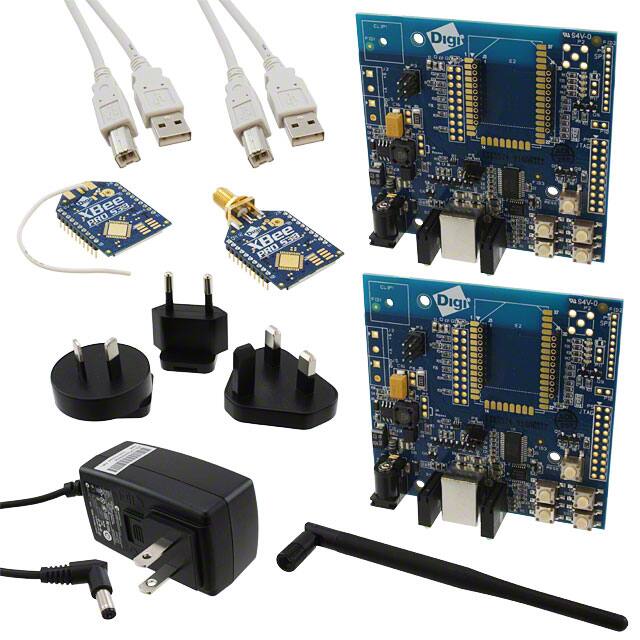
Identify Kit Components
Carefully unpack and verify the contents of your kit. Your kit should include the following:
XBee Module (2)
Power Supply
Antenna
XBee Interface Boards (2)
USB Cable (2)
Assemble your Development Kit
To assemble your development kit, perform the following steps:
1. Install the modules on the XBee Interface Boards (XBIB) by lining the pins up with the
headers and pressing the module into place.
2. Attach the dipole antenna to the RPSMA module.
3. Connect the first XBIB to your computer using a USB cable. This first device will be your
base radio.
4. Connect the remaining XBIB by either using the power supply or USB cable.
You are now ready to run the X‐CTU software and to begin configuring your XBee Network.
You have just completed Goal #1 ‐ setting up your
XBee‐PRO XSC (S3B) Development Kit.
© 2012 Digi International, Inc..
6
�Part 2: Download and Install Software
Installing USB Drivers
The XBee USB Interface Board is a “plug‐and‐play” device that should be detected by the PC
automatically. If you are using Windows 7 or Vista, the USB drivers should install and a notification will
appear in the lower right portion of your screen indicating success or failure. If the USB drivers fail to
install, please follow the USB driver installation instructions found here:
http://www.digi.com/support/kbase/kbaseresultdetl.jsp?id=3214.
If you are using Windows 2000 or XP, download and install the driver as per the following directions.
To install the USB driver:
1. Download the driver setup file at:
http://ftp1.digi.com/support/driver/FTDI_Windows_Driver_Setup.exe.
2. Double‐ click on the setup file. A window will pop up during installation and automatically close
when the process is complete.
Installing X-CTU Software
1. Download X‐CTU at www.digi.com/xctu.
2. Browse to the folder to which you saved the above install file.
3. Double‐click on the installer file and follow the X‐CTU Setup Wizard.
4. When asked if you would like to check Digi's web site for firmware updates, click Yes.
5. After the firmware updates are complete, click Close. Updates may take a few minutes, please be
patient.
6. Start X‐CTU by double‐clicking on the X‐CTU icon on your desktop, or by selecting Start > Programs
> Digi > X‐CTU.
You have just completed Goal #2 ‐ download and install
software.
© 2012 Digi International, Inc..
7
�Part 3: Test Communications Link
Perform a Range Test
To run the range test, perform the following steps:
1. Double‐click the X‐CTU shortcut on your desktop.
2. Under the PC Settings tab, select the serial COM port associated with the development boards you
have just attached to your computer.
3. Verify that the baud rate and data settings match the internal settings of the devices:
• Baud Rate: 9600
• Flow Control: NONE
• Data Bits: 8
• Parity: NONE
• Stop Bits: 1
Note: The baud rate needs to match the BD parameter in the radios for X-CTU
© 2012 Digi International, Inc..
8
�to communicate correctly with the radios. The default is 9600.
The range test works best if you attach the first XBIB to your computer and attach the
second device to a laptop. Increase the distance between the first (base) radio and the
second (remote) radio while monitoring the percentage of good packets on the laptop.
You will need to have a jumper at P8 on the loopback header on the XBIB for
the remote radio.
4. Select the Range Test tab.
5. (Optional) Check the “RSSI” check box to enable Received Signal Strength Indicator.
6. Click Start to begin the range test
© 2012 Digi International, Inc..
9
�7. Monitor the link quality by reading the Percent section on the Range Test tab. This section displays
the running percentage of good packets sent to the receiving radio and looped back to the base.
8. Click Stop to end the range test
You have just completed Goal #3 ‐ performing a range test
© 2012 Digi International, Inc..
10
�Part 4: Change Firmware Versions
These modules can be configured for an RF data rate of 9600 or 19200 baud with just a firmware change.
When integrating these radios with the XStream or old XBee‐PRO XSC product lines, the RF data rates
must match. For XStream radios starting with the part number X09‐009 or old XBee‐PRO XSC radios, use
the 9600 baud version. For XStream radios starting with the part number X09‐019, use the 19200 baud
version.
1. Click on the Modem Configuration tab in X‐CTU.
2. Select the modem type (XBP9B‐XC) from the Modem drop‐down box.
3. Select the function set that corresponds with the RF data rate desired, XBee‐PRO XSC‐S3B 9600 or
XBEE‐PRO XSC‐S3B 19200.
4. Select the firmware version desired from the Version drop‐down box. The default selected is the
newest version of the firmware.
5. Check the always update firmware box.
6. Click the Write button.
This sequence is also useful for switching between the regular firmware and the 920
MHz firmware.
© 2012 Digi International, Inc..
11
�XBe e‐ PRO XS C ( S 3 B ) Development K i t Getting Sta rted Gu ide
If you do not see the firmware version you are looking for in the
Version drop‐down box, you can query the firmware database for
updates. To do so, click on the Download new versions... button and
click Web. Any firmware versions not in X‐CTU's library will be
downloaded.
You have just completed Goal #4 ‐ Change Firmware Versions
© 2012 Digi International, Inc..
12
�Appendix A: Troubleshooting
Resetting the XBee-PRO XSC Module
Each XBee USB Interface Board has a reset button (located as shown below):
Pressing this button resets the module, but will not clear any changes written to the module. Pressing this
button will also reset the COM port for the board.
Resolving Radio Communication Issues
Other network settings that can cause loss of communication include Hopping Channel (HP), Baud Rate
(BD), and Parity (NB) among others. Check to see if these parameters are set appropriately. If you are
unsure if your settings are affecting your communication, you might want to try setting your modules
back to their default settings. To do so, go to the Modem Configuration tab in X‐CTU and click Restore.
Resolving Radio Responses in X-CTU
Check to make sure the loopback jumper is not bridging the P8 header on the interface board.
© 2012 Digi International, Inc..
13
�


 工商网监
湘ICP备2023018690号
工商网监
湘ICP备2023018690号
