Adafruit 1-Wire GPIO Breakout - DS2413
Created by Bill Earl
https://learn.adafruit.com/adafruit-1-wire-gpio-breakout-ds2413
Last updated on 2021-11-15 06:09:59 PM EST
©Adafruit Industries
Page 1 of 17
�Table of Contents
Overview
3
Assembly & Wiring
4
•
•
•
•
•
•
4
5
5
6
6
7
Headers
Position the Header
And Solder!
Wiring
Basic Wiring:
Wiring Multiple DS2413 Breakouts
Use it!
7
OneWire Library
8
• Download and Install
• Library Documentation
• DS2413 Example Sketch
8
9
9
Open Drain GPIO
11
Running the Example Code
13
• Download the example sketch from our Github repository:
• Wiring:
13
13
Reading, Writing and Arithmetic
14
•
•
•
•
14
14
15
15
myWire.read();
myWire.write(num);
Binary and Hexadecimal
Reading GPIO Pins
Downloads
• Files
• Schematic
• Fabrication Print
©Adafruit Industries
16
16
17
17
Page 2 of 17
�Overview
Pins are precious in the microcontroller world. How many times have you needed just
one more pin? Sure, you could step up to a Mega and get a whole bunch more, but
what if you really just need one or two? The DS2413 breakout board is the perfect
solution. Each DS2413 breakout has 2 open drain GPIO pins and a 1-Wire interface.
Just one of these boards will give you 2 pins for the price of one. But you can keep
expanding from there.
You can put as many of these boards as you want on the the 1-wire bus and still
control all of them with just one Arduino pin. Each chip has a 48-bit unique address,
which means (in theory*) you could have as many as 2 * 2^48 pins controlled by just
one Arduino pin! What could you control with 562 trillion pins?
* In practice, you would run out of Arduino memory long before that. But it's fun to
imagine!
©Adafruit Industries
Page 3 of 17
�Assembly & Wiring
The board comes pre-assembled and tested from our factory. We include optional
headers for breadboard use. Or you can wire the board directly into your project.
Headers
Installing the optional headers is a simple process and takes just a few minutes:
©Adafruit Industries
Page 4 of 17
�Position the Header
Cut the header strip to length if
necessary and place it in the breadboard
(long pins down!). Position the breakout
board over the header.
And Solder!
Solder each pin to assure a good
electrical connection. If you are new to
soldering, check out the Adafruit Guide
to Excellent Soldering. (https://adafru.it/
aTk)
©Adafruit Industries
Page 5 of 17
�Wiring
Wiring to the Arduino is simple as well. Just power, ground and a signal wire:
Basic Wiring:
• GND -> Arduino GND
• IO -> Arduino GPIO pin (The example code uses pin 8)
Then connect a 4.7K ohm pullup resistor (included) from IO to 5v.
©Adafruit Industries
Page 6 of 17
�Wiring Multiple DS2413 Breakouts
To add more breakouts, just connect more to the same GND and IO pin. Additional
pullup resistors are not required.
Use it!
Once connected to the onewire bus, the GPIO pins can be used for either input or
output. The following pages will show you how to control these pins via the onwire
library. We will also show you how to connect things to the open drain outputs of the
GPIO pins.
©Adafruit Industries
Page 7 of 17
�OneWire Library
Download and Install
The DS2413 uses the Maxim/Dallas OneWire protocol. You can download the OneWire
library (https://adafru.it/das) from the Arduino library manager.
Open up the Arduino library manager
©Adafruit Industries
Page 8 of 17
�Search for the OneWire library and install it. You'll have to scroll down a bit to find the
right one.
Library Documentation
Detailed documentation of the OneWire Library can be found at the PJRC site here:
OneWire Library Documentation and
Examples
https://adafru.it/das
DS2413 Example Sketch
We have an example sketch that shows how to use the OneWire library to talk to the
DS2413 GPIO pins here at GitHub: https://github.com/adafruit/
Adafruit_Learning_System_Guides/tree/master/Adafruit_DS2413 (https://adafru.it/
EDu)
DS2413 Example Sketch Download
https://adafru.it/EDv
// SPDX-FileCopyrightText: 2014 Bill Earl for Adafruit Industries
//
// SPDX-License-Identifier: MIT
©Adafruit Industries
Page 9 of 17
�#include
#define DS2413_ONEWIRE_PIN
(8)
#define
#define
#define
#define
#define
0x3A
0xF5
0x5A
0xAA
0xFF
DS2413_FAMILY_ID
DS2413_ACCESS_READ
DS2413_ACCESS_WRITE
DS2413_ACK_SUCCESS
DS2413_ACK_ERROR
OneWire oneWire(DS2413_ONEWIRE_PIN);
uint8_t address[8] = { 0, 0, 0, 0, 0, 0, 0, 0 };
void printBytes(uint8_t* addr, uint8_t count, bool newline=0)
{
for (uint8_t i = 0; i < count; i++)
{
Serial.print(addr[i]>>4, HEX);
Serial.print(addr[i]&0x0f, HEX);
Serial.print(" ");
}
if (newline)
{
Serial.println();
}
}
byte read(void)
{
bool ok = false;
uint8_t results;
oneWire.reset();
oneWire.select(address);
oneWire.write(DS2413_ACCESS_READ);
results = oneWire.read();
/* Get the register results
ok = (!results & 0x0F) == (results >> 4); /* Compare nibbles
results &= 0x0F;
/* Clear inverted values
*/
*/
*/
oneWire.reset();
// return ok ? results : -1;
return results;
}
bool write(uint8_t state)
{
uint8_t ack = 0;
/* Top six bits must '1' */
state |= 0xFC;
oneWire.reset();
oneWire.select(address);
oneWire.write(DS2413_ACCESS_WRITE);
oneWire.write(state);
oneWire.write(~state);
ack = oneWire.read();
if (ack == DS2413_ACK_SUCCESS)
{
oneWire.read();
}
oneWire.reset();
/* Invert data and resend
*/
/* 0xAA=success, 0xFF=failure */
/* Read the status byte
*/
return (ack == DS2413_ACK_SUCCESS ? true : false);
}
void setup(void)
©Adafruit Industries
Page 10 of 17
�{
Serial.begin(9600);
Serial.println(F("Looking for a DS2413 on the bus"));
/* Try to find a device on the bus */
oneWire.reset_search();
delay(250);
if (!oneWire.search(address))
{
printBytes(address, 8);
Serial.println(F("No device found on the bus!"));
oneWire.reset_search();
while(1);
}
/* Check the CRC in the device address */
if (OneWire::crc8(address, 7) != address[7])
{
Serial.println(F("Invalid CRC!"));
while(1);
}
/* Make sure we have a DS2413 */
if (address[0] != DS2413_FAMILY_ID)
{
printBytes(address, 8);
Serial.println(F(" is not a DS2413!"));
while(1);
}
Serial.print(F("Found a DS2413: "));
printBytes(address, 8);
Serial.println(F(""));
}
void loop(void)
{
/* Read */
/*
uint8_t state = read();
if (state == -1)
Serial.println(F("Failed reading the DS2413"));
else
Serial.println(state, BIN);
*/
/* Write */
bool ok = false;
ok = write(0x3);
if (!ok) Serial.println(F("Wire failed"));
delay(1000);
ok = write(0x0);
if (!ok) Serial.println(F("Wire failed"));
delay(1000);
}
Open Drain GPIO
The DS2413 outputs are "Open Drain". What that means is that the output is the
"Drain" of an N-channel FET:
©Adafruit Industries
Page 11 of 17
�Internally, the "Source" of the FET is connected to Ground. But the Drain is left open.
When switched on, the FET provides a path for current to flow from the output pin to
ground.
Since there is no internal connection to VCC, the open drain output does not put out
a voltage like an Arduino GPIO pin. You have to provide your own external pullup.
While this may seem inconvenient, the open drain configuration allows for a lot of
flexibility. Since the output voltage is not dependent on the operating voltage of the
breakout, you can use a variety of power sources. The FETs in the DS2413 are
capable of switching voltages up to 28v and up to 20mA.
The diagram below from the DS2413 data sheet (https://adafru.it/deP) shows how
input and output connections should be made - with an external pullup to a local
power source.
For more information, refer to the DS2413 data sheet:
©Adafruit Industries
Page 12 of 17
�DS2413 Data Sheet
https://adafru.it/deP
Running the Example Code
Download the example sketch from our Git
hub repository (https://adafru.it/deQ):
Download Example Code
https://adafru.it/EDu
Wiring:
Connect a LED to IOA and IOB as follows:
• Cathode (short leg) of LED connected to the GPIO pin.
• Anode (long leg) of LED connected to one end of a resistor*.
• Other end of the resistor connected to 5v.
* A 1K resistor is shown here as a 'safe' value. For maximum LED brightness, you can
learn how to calculate the optimum resistance in this guide: http://learn.adafruit.com/
all-about-leds (https://adafru.it/clH)
©Adafruit Industries
Page 13 of 17
�Compile and upload the example sketch and you should see both LEDs blinking: 1
second on and 1 second off.
Reading, Writing and Arithmetic
Reading and writing to the DS2413 is via the read() and write() functions of the
Onewire library:
myWire.read();
Read a byte.
myWire.write(num);
Write a byte.
These functions read and write a byte at a time. So you need to use a little binary
arithmetic to separate out the 2 bits corresponding to the 2 GPIO pins.
In the example code, the 2 LEDs are flashed by alternately writing 0x0 and 0x3.
/* Write */
bool ok = false;
ok = write(0x3);
if (!ok) Serial.println(F("Wire failed"));
delay(1000);
ok = write(0x0);
if (!ok) Serial.println(F("Wire failed"));
delay(1000);
©Adafruit Industries
Page 14 of 17
�Binary and Hexadecimal
The 0x3 in the example is the hexadecimal equivalent to the binary number B00000
011. In the DS2413, the low-order bit (the one to the far right) corresponds to IOA and
the one next to it corresponds to IOB. Writing 0x3 writes a binary '1' to both pins and
turns them both on.
To turn on just IOA you could write 0x1 (B00000001). And to turn on just IOB, you
could write 0x2 (B00000010).
If you substitute the following code, the LEDs will flash alternately:
/* Write */
bool ok = false;
ok = write(0x1);
if (!ok) Serial.println(F("Wire failed"));
delay(1000);
ok = write(0x2);
if (!ok) Serial.println(F("Wire failed"));
delay(1000);
Or, if you prefer, you can use the binary representation instead:
/* Write */
bool ok = false;
ok = write(B00000001);
if (!ok) Serial.println(F("Wire failed"));
delay(1000);
ok = write(B00000010);
if (!ok) Serial.println(F("Wire failed"));
delay(1000);
For more on integer constants in the different number bases, see the Arduino Integer
Constants (https://adafru.it/deR)page.
Reading GPIO Pins
Reading is a little trickier: You need to separate the individual pin values from the byte
that is returned from the read(). A read can return one of 5 values:
• 0x0 (B00000000) - Both pins LOW
• 0x1 (B00000001) - IOA = HIGH, IOB = LOW
• 0x2 (B00000010) - IOA = LOW, IOB = HIGH
• 0x3 (B00000011) - Both pins HIGH
• 0xFF (B11111111) - Read Failed!
©Adafruit Industries
Page 15 of 17
�To extract the state of an individual pin, you will need to use a little binary math (https
://adafru.it/deS). In particular the "bitwise AND" operator: "&".
If you AND the read value from the GPIO breakout with the bit pattern of the pin you
are interested in, you will get a boolean "TRUE" if the pin is HIGH and a "FALSE" if the
pin is LOW. The following code snippet prints "A" if IOA is HIGH and "B" if IOB is HIGH.
uint8_t state = read();
const int IOA = 0x1;
const int IOB = 0x2;
if (state == -1)
{
Serial.println(F("Failed reading the DS2413"));
}
else
{
if (state & IOA)
{
Serial.println("A");
}
if (state & IOB)
{
Serial.println("B");
}
}
Downloads
Files
• Datasheet for the DS2413 (https://adafru.it/deT)
• Product page for the DS2413 (https://adafru.it/deU)
• One-Wire overview (https://adafru.it/deV)
• EagleCAD PCB files on GitHub (https://adafru.it/rAs)
• Fritzing object in Adafruit Fritzing library (https://adafru.it/aP3)
©Adafruit Industries
Page 16 of 17
�Schematic
Fabrication Print
©Adafruit Industries
Page 17 of 17
�
很抱歉,暂时无法提供与“1551”相匹配的价格&库存,您可以联系我们找货
免费人工找货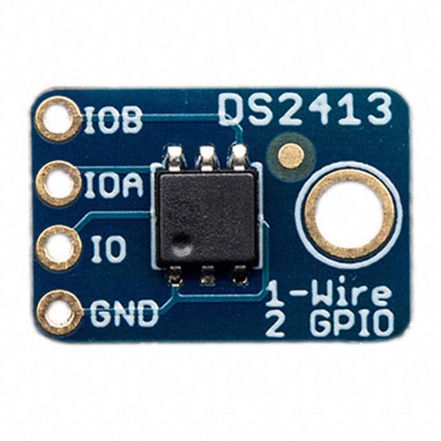


 工商网监
湘ICP备2023018690号
工商网监
湘ICP备2023018690号
