599 Menlo Drive, Suite 100
Rocklin, California 95765, USA
Office: (916) 624-8333
Fax: (916) 624-8003
General: info@parallax.com
Technical: support@parallax.com
Web Site: www.parallax.com
Educational: www.parallax.com/sic
Parallax Servo Controller (#28023) – Rev B
16-Channel Servo Control with Ramping
Introduction
Robots, robots, robots; and, the bigger they get, the more servos and I/O are required to enable them to
fulfill their duties. The Parallax Servo Controller, PSC, controls up to 16 servos, and may be networked
together so that two PSCs can control 32 servos using a single I/O line.
The PSC manages all of the servo pulses so your host controller doesn’t have to. Additionally, the
ramping function allows you to individually set the speed of each servo. With ramping, you can tell the
servo where to go, and just how fast to get there. The result is true, “set-it and forget-it” functionality.
Packing List
Verify that your Parallax Servo Controller is complete in accordance with the list below:
Parallax Servo Controller
Shunt-Jumper
3-Conductor Cable
Documentation
Features
Runtime Selectable Baud rate. A serial message switches the baud rate from: 2400 to 38k4.
16 Servos. Servos driven simultaneously, continuously, 0-180˚ of rotation, 2uS resolution.
Servo Ramping. Choose one of 63 ramp rates for each servo.
Position Reporting. User may request position of an individual servo at any time.
Network Ready. Two modules may be linked together to drive 32 servos at the same time.
Before You Begin
The processor used on the PSC requires a supply 5 VDC. Use a separate power supply for
your servos. In general, servos require 4-7.5 VDC. Be sure that the servo power source can
supply ample current at the proper voltage and will not damage the servos.
Parallax, Inc. • Parallax Servo Controller – Rev B ver2.4 (#28023) • 1/2005
1
�Getting Started
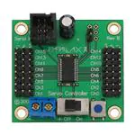
Locate and remove the Parallax Servo Controller from its protective anti-static bag. It should closely
resemble the image shown in Figure 1.
Figure 1: Parallax Servo Controller – Rev B
+
+
Serial In
- +S
Ch15
Ch13
Ch11
Ch9
Ch7
Ch5
Ch3
Ch1
Rev B
Ch14
Ch12
Ch10
Ch8
Ch6
Ch4
Ch2
Ch0
S+ -
© 2004
Mount the Parallax Servo Controller using 4-40 screws (or equivalent). Figure 2 details the mountinghole spacing and other dimensions of the PSC Rev A, which are the same for the Rev B board as well.
Figure 2: Parallax Servo Controller Mounting Holes
1.5” (38 mm)
Rev A
1.4”
(35.5 mm)
1.7”
(43 mm)
Servo Controller
© 2004
1.8” (46 mm)
Ensure the servo power switch on the Parallax Servo Controller is off, and then connect the power source
for the servos to the screw terminals observing proper polarity. The power source for the servos
must be a separate power source from that of the Board of Education Rev C. This document
assumes the host system is a BS2 module plugged into a Board of Education Rev C from Parallax, though
those items are not required for proper operation. A three-conductor cable (included) connects the
Ground, +5VDC, and serial I/O line to the host system. If you are not using the Rev C BOE, connect the
wires of the three-conductor cable to VSS (black), +5VDC (red), and the I/O pin of your choice on your
host system. Note the I/O pin number on the BOE that is connected as the serial I/O line on the PSC.
This document assumes you have connected this cable into X4, slot 15. Ensure that the Vservo jumper
selector, (between X4 and X5 on the BOE Rev C), is set to the VDD position. Connect your servos to the
3 pin terminals provided. Figure 3 is an example showing the Parallax Servo Controller connected to two
servos and the Board of Education.
2
Parallax, Inc. • Parallax Servo Controller – Rev B ver 2.4 (#29023) • 1/2005
�Figure 3: Parallax Servo Controller, typical Connections.
standard servo
standard servo
www.parallax.com
www.parallax.com
15 14 Vdd 13 12
6-9VDC
9 Vdc
Battery
Red
Black
X4
Pwr
STA
in MPS
CLA
SS
TM
1
Rev A
Servo Controller
© 2004
Sout
Sin
ATN
Vss
P0
P1
P2
P3
P4
P5
P6
P7
U1
Vin
Vss
Rst
Vdd
P15
P14
P13
P12
P11
P10
P9
P8
Vss
P0
P2
P4
P6
P8
P10
P12
P14
Vdd
Vss
P1
P3
P5
P7
P9
P11
P13
P15
Vin
X1
Reset
Vdd
X5
Vin
Vss
X3
P15
P14
P13
P12
P11
P10
P9
P8
P7
P6
P5
P4
P3
P2
P1
P0
X2
0 1 2
www.parallax.com/sic
Board of Education
Rev C
© 2000-2003
7.5 VDC max
Follow the instructions in this document when making connections to the PSC. To power up your PSC,
slide the power switch on the BOE to the “2” position. You should see the red LED illuminate on the PSC
as well as the green LED light on the BOE.
Serial Command Format
The PSC supports several commands that are sent to it via RS-232 serial protocol. The voltage swing of
this serial line is 0-5 VDC (TTL level). Each serial command must be preceded with an exclamation point,
“!”, and the pair of letters, “SC”.
When your PSC starts up, the default baudrate is 2400 N 8 2, (no parity, eight data bits, two stop bits)
true data, open-drain (driven low, pulled high). The exclamation point is used in some AppMods to
determine the incoming baudrate, thereby supporting a feature called Auto-Baud. The PSC does not
support Auto-Baud. The “SC” portion is an identifier that pertains to the PSC. Together, the “!” and the
“SC” form a preamble, “!SC”. The preamble serves to distinguish commands for the PSC from other
messages on the serial I/O line, and allow different types of AppMods to use the same serial line.
After the preamble is sent, the command and associated parameters are sent. The eighth and final
character sent is a $0D, (CR), used to terminate the string. If the command causes the PSC to reply, a
three-byte reply is sent after a 1.5 mS delay.
Parallax, Inc. • Parallax Servo Controller – Rev B ver2.4 (#28023) • 1/2005
3
�VER? Command – Identify Firmware Version Number
Syntax: “!SCVER?” $0D
Reply: “1.3”
The VER? command causes the PSC to reply with its firmware version number. A string terminator, $0D,
must follow each command; note that you may use the constant CR instead. The version number
divulged pertains to the version of firmware contained within the IC. The following code snippet can be
used to find and identify your PSC.
'{$PBASIC 2.5}
Sdat
Baud
buff
FindPSC:
DEBUG
SEROUT
SERIN
DEBUG
STOP
PIN
CON
VAR
15
396
Byte(3)
' Serial Data I/O pin
' Constant for 2400 baud
' temporary variable
' Find and get the version
"Finding PSC", CR
' number of the PSC.
Sdat, Baud+$8000, ["!SCVER?",CR]
Sdat, Baud, 500, FindPSC, [STR buff\3]
"PSC ver: ", buff(0), buff(1), buff(2), CR
Within the DEBUG window, you will see a series of “Finding PSC” messages. The Stamp should find the
unit immediately. This is evidenced by the PSC replying with a number like “1.3”, which is it’s firmware
version number. If after 3 or 4 messages the PSC has not been found, you should check that all the
connections are proper and that power is applied. If the PSC fails to respond, you may momentarily push
the Reset button on the PSC. If the PSC fails to respond, contact Parallax Technical Support at (916)
624-8333.
SBR Command – Set the Baudrate (to either 2400 or 38K4 Baud)
Syntax: “!SCSBR” x $0D
Reply: “BR” x (where x is either 0 for 2400, or 1 for 38K4)
After establishing communications with the PSC you may wish to elevate the baudrate to 38K4 baud. To
do this, you may follow the example in the following code snippet.
'{$PBASIC 2.5}
Sdat
Baud
buff
PIN
CON
VAR
15
396
Byte(3)
' Serial Data I/O pin
' Constant for 2400 baud
' temporary variable
SetBaud:
DEBUG "Setting Baudrate", CR
SEROUT Sdat, Baud+$8000, ["!SCSBR",1,CR]
SERIN Sdat, 6,500, SetBaud, [STR buff\3]
DEBUG "Baud reply: ", buff(0), buff(1), DEC1 buff(2), CR
STOP
Note that the SERIN command’s baudmode is set to 6 (38K4). That’s because the PSC will reply to the
command with the new baudrate to confirm the command has been executed. If you wished to set the
4
Parallax, Inc. • Parallax Servo Controller – Rev B ver 2.4 (#29023) • 1/2005
�baudrate back to 2400, you must either reset the controller or send it a SBR, $0 command at 38K4
baudrate. Once the baud rate has been changed, it would be wise to “ping” the servo controller from
time to time. If either the BASIC Stamp or the PSC reset without the other resetting, they could be left in
the state of different baud rates. When “pinging” the PSC with an VER? command, the BASIC Stamp’s
SERIN function should employ its timeout feature. At this timeout label, you can them attempt to VER?
the PSC at the other baudrate. Once identified, the baudrate can again be set, and the program can
resume.
Position Command – Set the Position of a Servo Channel
Syntax: “!SC” C R pw.LOWBYTE, pw.HIGHBYTE, $0D
Reply: none
To control a servo, you must write a position command to the PSC. Each position command is comprised
of a header, three parameters: C, R, and PW, and a command terminator.
The Header: “!SC” is the header. The header signifies to all devices on the same wire that this is a
command for a Servo Controller.
The C parameter is a binary number 0-31 corresponding to the servo channel number. The servo
channel number should be 0-15 with no jumper present on the PSC, or 16-31 with the jumper present.
With a jumper present on the PSC, servo channel 0 become channel 16, channel 1 becomes 17, etc.
The R parameter is a binary number 0 – 63 that controls the ramp function for each channel. If the ramp
parameter is set to 0, ramping is disabled and the pulse width will be set to the P parameter sent
immediately. Ramp values of 1-63 correspond to speeds from ¾ of a second up to 60 seconds for a full
500uSec to 2.50 mSec excursion for standard servos. This correlation is rather linear though no equation
presently exists.
The P parameter is a 16-bit Word that corresponds to the desired servo position. The range, (250-1250),
corresponds to 0 to 180 degrees of servo rotation with each step equaling 2 uSec.
The command terminator, $0D, (CR), must not be omitted.
The following code snippet demonstrates the Position Command by ramping a servo channel 11 from 0 to
255 at ramp rate 7.
'{$PBASIC
ch
VAR
pw
VAR
ra
VAR
Sdat CON
baud CON
2.5}
Byte
Word
Byte
15
396
ra = 7
ch = 11
DO
pw = 1250
SEROUT Sdat, Baud+$8000,["!SC", ch, ra, pw.LOWBYTE, pw.HIGHBYTE, CR]
PAUSE 1000
pw = 250
SEROUT Sdat, Baud+$8000,["!SC", ch, ra, pw.LOWBYTE, pw.HIGHBYTE, CR]
PAUSE 1000
LOOP
Note: Not all servos are exactly alike. If your servos appear to
strain when commanded to position 250, you should increase the
Parallax, Inc. • Parallax Servo Controller – Rev B ver2.4 (#28023) • 1/2005
5
�250 up to 260 (or so) to prevent the servo from straining itself.
Similarly, if your servo strains when commanded to go to position
1250, you should decrease the 1250 to 1240 or so to prevent the
servo from straining itself.
RSP Command – Report the Position of a Servo Channel
Syntax: “!SCRSP” x $0D
Reply: x y z(where x is the channel number, and z:y is the value reported)
Sometimes it is necessary to know the current servo position. The RSP command returns the value of
the specified servo channel. If the servo is still moving as a result of a ramp command, the position may
still be read. The following code snippet demonstrates how to use this command.
'{$PBASIC
ch
VAR
pw
VAR
ra
VAR
x
VAR
Buff VAR
Sdat CON
baud CON
2.5}
Byte
Word
Byte
Byte
Byte(3)
15
396
Init:
ra =
15: ch = 0
DO
pw = 1240: GOSUB WRservo
pw = 240: GOSUB WRservo
LOOP
WRservo:
SEROUT Sdat, Baud+$8000,["!SC", ch, ra, pw.LOWBYTE, pw.HIGHBYTE, CR]
FOR x = 0 TO 4
PAUSE 1000
SEROUT Sdat, Baud+$8000, ["!SCRSP", ch, CR]
SERIN Sdat, Baud, 1000, Init,[STR Buff\3]
DEBUG "Servo ", DEC buff(0), " ", HEX2 buff(1), " :", HEX2 buff(2), CR
NEXT
RETURN
Within the DO-LOOP, this program sets the pulse width (pw) to one extreme or the other and writes this
value to the PSC. The ramp value (ra) was set to give the program time to poll the servo position several
times. Within the WRservo subroutine, the new pw is sent, and the position is polled five times, once
each second. A DEBUG command is used to format the reply and post it to a window for your review.
6
Parallax, Inc. • Parallax Servo Controller – Rev B ver 2.4 (#29023) • 1/2005
�Networking Two PSCs Together
It is possible to network two PSCs together to control up to 32 servos. Simply use a second 3-Conductor
cable to daisy chain two PSCs together as shown in Figure 6. The presence of a shunt differentiates
between Unit 0 (channels 0-15) and Unit 1 ( channels 16-31).
Figure 4: PSC without jumper (Ch0-15).
+
+
Serial In
- +S
Rev B
Ch15
Ch13
Ch11
Ch9
Ch7
Ch5
Ch3
Ch1
Ch14
Ch12
Ch10
Ch8
Ch6
Ch4
Ch2
Ch0
S+ -
Figure 5: PSC with jumper (Ch16-31).
+
GND
+5
Serial I/O
- +S
Ch31
Ch29
Ch27
Ch25
Ch23
Ch21
Ch19
Ch17
© 2004
+
Serial In
Ch15
Ch13
Ch11
Ch9
Ch7
Ch5
Ch3
Ch1
GND
+5
Aux 1
Rev B
Ch14
Ch12
Ch10
Ch8
Ch6
Ch4
Ch2
Ch0
S+ -
Ch30
Ch28
Ch26
Ch24
Ch22
Ch20
Ch18
Ch16
© 2004
Figure 6: Two PSCs daisy chained together.
15 14 Vdd 13 12
6-9VDC
9 Vdc
Battery
X4
Pwr
STA
in MPS
CL A
SS
TM
1
Sout
Sin
ATN
Vss
P0
P1
P2
P3
P4
P5
P6
P7
+
Red
Black
U1
Vin
Vss
Rst
Vdd
P15
P14
P13
P12
P11
P10
P9
P8
Vss
P0
P2
P4
P6
P8
P10
P12
P14
Vdd
Vss
P1
P3
P5
P7
P9
P11
P13
P15
Vin
X1
Reset
Vin
Vss
X3
P15
P14
P13
P12
P11
P10
P9
P8
P7
P6
P5
P4
P3
P2
P1
P0
Ch15
Ch13
Ch11
Ch9
Ch7
Ch5
Ch3
Ch1
© 2004
Rev B
Ch14
Ch12
Ch10
Ch8
Ch6
Ch4
Ch2
Ch0
S+ -
+
Serial In
- +S
Ch15
Ch13
Ch11
Ch9
Ch7
Ch5
Ch3
Ch1
Rev B
Ch14
Ch12
Ch10
Ch8
Ch6
Ch4
Ch2
Ch0
S+ -
© 2004
Ch 0-15
Ch 16-31
X2
0 1 2
www.parallax.com/sic
Vdd
- +S
X5
+
+
Serial In
Board of Education
Rev C
© 2000-2003
Please note that in this configuration when you send a serial command to one unit, you send it to both.
Commands that set servo positions are the only commands ignored by the other unit. All other
commands invoke a reply. Unit 0 replies first. Unit 1 replies approximately 3 mS later. Since all replies
are fixed at 3 byte lengths, you would need to configure your SERIN command to receive six bytes.
Parallax, Inc. • Parallax Servo Controller – Rev B ver2.4 (#28023) • 1/2005
7
�Revision List
Hardware
Firmware
-------------------------------------------------------------------------------------------------------------------------------Rev A
1.0
(Only Beta units released)
90 degree rotation, 4 uSec resolution, 1-2 mS pulses, 8 bit PWM, 15 possible ramp values, position
polling, and a serial interface at 38k4 Baud. You could daisy-chain this unit, but the fact that there was
only one comm connection made it difficult. The bulk of the silkscreen was on the PCB bottom. Glitch
(due to comms) on Ch0 and Ch8 removed.
-------------------------------------------------------------------------------------------------------------------------------Rev B
1.1
released March 1st, 2004
The connectors were changed slightly to accommodate easier to implement daisy-chain scheme. The
silkscreen was corrected so that pertinent info was on pcb top. The serial interface was expanded to
support either 2400 Baud or 38k4 Baud.
-------------------------------------------------------------------------------------------------------------------------------Rev B
1.2
released March 16th, 2004
The firmware was enhanced to support 16-bit pwm, 180 degree rotation, 2uSec resolution, and 63 ramp
rates. Serial code was optimized to accept messages faster than the BS2 could send them.
-------------------------------------------------------------------------------------------------------------------------------Rev B
1.3
released April 19th, 2004
Report position bug in the firmware was found and corrected. Specifically, when polling a servo position,
the position of the last servo written to was reported regardless of the requested channel number.
Rev B
1.4
released January 12th, 2005
Some conditions caused interrupt contention within the PSoC chip which in turn caused a small amount of
glitch on some of the output channels. This glitch caused some servos to oscillate when they should
have been still. The PWM channels were restructured such that interrupt contention no longer affects
PWM performance. The output glitch has been reduced from +-2uS to less than +- 100 nS.
Note: your PSC is re-programmable. If your PSC firmware is not current, you may send it in to Parallax
for a free firmware upgrade. Your only cost is the shipping fee.
Liability Disclaimer
Parallax, Inc. is not responsible for special, incidental, or consequential damages resulting from any
breach of warranty, or under any legal theory, including lost profits, downtime, goodwill, damage to or
replacement of equipment or property, and any costs of recovering, reprogramming, or reproducing any
data stored in or used with Parallax products.
8
Parallax, Inc. • Parallax Servo Controller – Rev B ver 2.4 (#29023) • 1/2005
�Figure 6: PSC Rev B Schematic
Parallax, Inc. • Parallax Servo Controller – Rev B ver2.4 (#28023) • 1/2005
9
�


 工商网监
湘ICP备2023018690号
工商网监
湘ICP备2023018690号
