ARDUINO GSM SHIELD 2
( I N T E G R AT E D A N T E N N A )
Code: A000105
The Arduino GSM Shield V2 allows your Arduino board to make
phone calls, send SMS and connect to the Internet.
The Arduino GSM Shield 2 allows an Arduino board to connect to the internet,
make/receive voice calls and send/receive SMS messages. The shield uses a radio
modem M10 by Quectel. It is possible to communicate with the board using AT
commands. The GSM library has a large number of methods for communication
with the shield.
https://www.arduino.cc/en/Reference/GSM
�The shield uses digital pins 2 and 3 for software serial communication with the
M10. Pin 2 is connected to the M10’s TX pin and pin 3 to its RX pin. See these
notes for working with an Arduino Mega, Mega ADK, or Leonardo. The modem's
PWRKEY pin is connected to Arduino pin 7.
https://www.arduino.cc/en/Guide/GSMShieldLeonardoMega
The M10 is a Quad‐band GSM/GPRS modem that works at frequencies
GSM850MHz, GSM900MHz, DCS1800MHz and PCS1900MHz. It supports TCP/UDP
and HTTP protocols through a GPRS connection. GPRS data downlink and uplink
transfer speed maximum is 85.6 kbps.
To interface with the cellular network, the board requires a SIM card provided by a
network operator. See the getting started page for additional information on SIM
usage.
https://www.arduino.cc/en/Guide/ArduinoGSMShieldV2#toc4
The most recent revision of the board uses the 1.0 pinout on rev 3 of the Arduino
Uno board.
Requires an Arduino board (not included)
Operating voltage 5V (supplied from the Arduino Board)
Connection with Arduino Uno on pins 2, 3 (Software Serial) and 7 (reset). See these
notes for working with a Mega, Mega ADK, or Leonardo.
https://www.arduino.cc/en/Guide/GSMShieldLeonardoMega
This version includes an integrated antenna
�OSH: Schematics
Arduino GSM Shield 2 is open‐source hardware! You can build your own board
using the following files:
EAGLE FILES IN .ZIP
https://www.arduino.cc/en/uploads/Main/arduino‐gsm‐shield‐06‐reference‐
design.zip
SCHEMATICS IN .PDF
https://www.arduino.cc/en/uploads/Main/Arduino‐GSM‐Shield2‐Rev3.2‐SCH.pdf
SIM to use with this shield
The GSM shield 2 is compatible with Data only and Voice and Data SIM. GPRS and
SMS are supported by 2G Data only SIM, while voice calls, supported by the
hardware, require a Voice and Data SIM, the same you may use in a GSM mobile
phone. The Data transfer is based on GPRS technology and therefore it is not
compatible with 3G or UMTS only network providers. GPRS is a 2G technology.
Power
It is recommended that the board be powered with an external power supply that
can provide between 700mA and 1000mA. Powering an Arduino and the GSM
shield 2 from a USB connection is not recommended, as USB cannot provide the
required current for when the modem is in heavy use.
On board indicators
The shield contains a number of status LEDs:
On: shows the Shield gets power.
Status: turns on to when the modem is powered and data is being transferred to/from
the GSM/GPRS network.
Net: blinks when the modem is communicating with the radio network.
On board interfaces
The shield comes with a on‐board audio jack as well, and it can be used for both
microphone and line inputs. It is also possible to make voice calls. You don’t need
to add a speaker and microphone.
There are two small buttons on the shield. The button labeled "Reset" is tied to
the Arduino reset pin. When pressed, it will restart the sketch. The button labeled
"Power" is connected to the modem and will power the modem on and off. For
�early versions of the shield, it was necessary to press the power button to turn on
the modem. Newer versions of the board will turn the modem on automatically.
If you have an early version of the shield, and it does not turn on automatically,
you can solder a jumper to the CTRL/D7 pad on the reverse side of the board, and
it will turn on when an attached Arduino receives power.
Several of the modem pins are exposed on the underside of the board. These
provide access to the modem for features like speaker output and microphone
input. See the datasheet for complete information.
�
Previous Versions
Do you own a past an old version of this product? Check Arduino GSM Shield
V1 product page.
https://www.arduino.cc/en/Main.ArduinoGSMShieldV1
https://store.arduino.cc/usa/arduino‐wireless‐proto‐shield 12‐7‐17
�
很抱歉,暂时无法提供与“A000105”相匹配的价格&库存,您可以联系我们找货
免费人工找货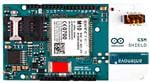


 工商网监
湘ICP备2023018690号
工商网监
湘ICP备2023018690号
