Adafruit LSM9DS0 Accelerometer + Gyro
+ Magnetometer 9-DOF Breakouts
Created by lady ada
https://learn.adafruit.com/adafruit-lsm9ds0-accelerometer-gyro-magnetometer-9-dofbreakouts
Last updated on 2021-11-15 06:16:16 PM EST
©Adafruit Industries
Page 1 of 26
�Table of Contents
Overview
3
Pinouts
5
•
•
•
•
•
•
•
•
6
6
6
7
7
7
8
8
Flora Sewable Version Pinouts
Power Pins
Data pins
Breadboard-Friendly Breakout Version
Power Pins
I2C Pins
SPI Pins
Interrupt & Misc Pins
Assembly
8
• Prepare the header strip:
• Add the breakout board:
• And Solder!
9
9
10
Arduino Code
11
•
•
•
•
•
•
•
•
Wiring for Flora
Wiring for Arduino
Download Arduino Libraries
Load Demo Sketch
Library Reference
Begin!
Set Ranges
Read data
11
11
12
13
16
17
17
17
Python & CircuitPython
18
•
•
•
•
•
•
18
19
20
21
21
23
CircuitPython Microcontroller Wiring
Python Computer Wiring
CircuitPython Installation of LSM9DS0 Library
Python Installation of LSM9DS0 Library
CircuitPython & Python Usage
Full Example Code
Python Docs
24
FAQs
24
Downloads
24
•
•
•
•
•
Datasheets
Breakout Board Schematic
Breakout Board PCB Print
Flora Breakout Schematics
Flora Breakout PCB Print
©Adafruit Industries
24
25
25
26
26
Page 2 of 26
�Overview
Add motion, direction and orientation sensing to your Arduino project with this all-inone 9-DOF sensor. Inside the chip are three sensors, one is a classic 3-axis
accelerometer, which can tell you which direction is down towards the Earth (by
measuring gravity) or how fast the board is accelerating in 3D space. The other is a 3axis magnetometer that can sense where the strongest magnetic force is coming
from, generally used to detect magnetic north. The third is a 3-axis gyroscope that
can measure spin and twist. By combining this data you can REALLY orient yourself.
©Adafruit Industries
Page 3 of 26
�When we saw the new LSM9DS0 from ST micro we thought - wow this could really
make for a great breakout, at a very nice price! Design your own activity or motion
tracker with all the data... We spun up a breakout board and Flora breakout that has
all the extra circuitry you'll want, depending on whether you are using it with the
Adafruit Flora or an Arduino (or other microcontroller)
The breakout board version of this sensor has both I2C and SPI interfaces. Attaching
it to the Arduino is simple, power Vin and GND with 3-5VDC, and wire up I2C data on
SCL and SDA, and you're ready to go! More advanced users can use SPI, our library
has support for both. The breakout comes fully assembled and tested, with some
extra header so you can use it on a breadboard. Four mounting holes make for a
secure connection, and we put the popular power+data pins on one side, and the
interrupt pins on the other side for a nice & compact breakout.
©Adafruit Industries
Page 4 of 26
�The Flora version has just I2C interface for a super-small design. Attaching it to the
FLORA is simple: line up the sensor so its adjacent to the SDA/SCL pins and sew
conductive thread from the 3V, SDA, SCL and GND pins. They line up perfectly so you
will not have any crossed lines. You can only connect one of these sensors to your
FLORA, but you can connect other I2C sensors/outputs by using the set of SCL/SDA
pins on the opposite side.
Pinouts
We have two versions of this sensor, a compact and sewable Flora sensor and also a
more extensive breadboard-friendly breakout. They use the same chip sensor, of
course, and the same firmware code. However there's some differences about the
pinouts!
©Adafruit Industries
Page 5 of 26
�Flora Sewable Version Pinouts
Power Pins
There's two power pins, 3V and GND. The 3V has to be regulated 'cleanly' from the
Flora. There's no on-board polarity or regulation! The GND pin is the ground for both
power and signal.
Data pins
Flora uses a chainable I2C data path for sensors, all the sensors share the same SCL
and SDA pins. These pins have 10K pullups to 3V but they do not have level shifting
so they are only for use with 3V logic boards such as Flora!
©Adafruit Industries
Page 6 of 26
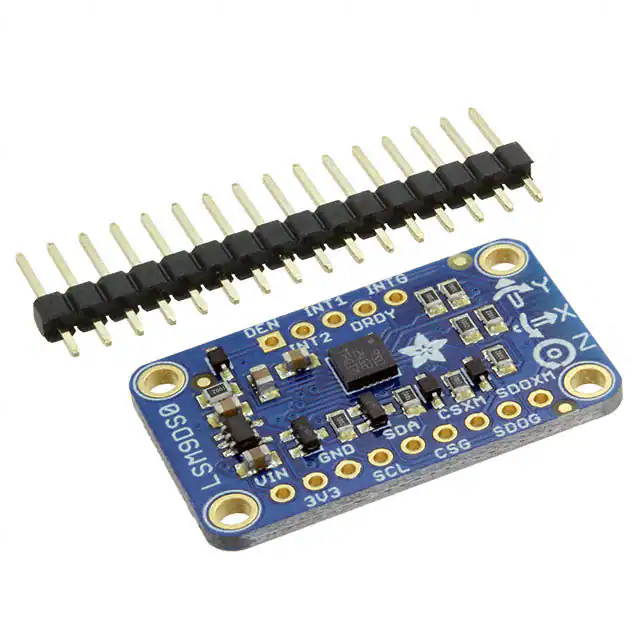
�Breadboard-Friendly Breakout Version
Power Pins
The sensor on the breakout requires 3V power. Since many customers have 5V
microcontrollers like Arduino, we tossed a 3.3V regulator on the board. Its ultra-low
dropout so you can power it from 3.3V-5V just fine.
• Vin - this is the power pin. Since the chip uses 3 VDC, we have included a
voltage regulator on board that will take 3-5VDC and safely convert it down. To
power the board, give it the same power as the logic level of your
microcontroller - e.g. for a 5V micro like Arduino, use 5V
• 3V3 - this is the 3.3V output from the voltage regulator, you can grab up to
100mA from this if you like
• GND - common ground for power and logic
I2C Pins
• SCL - I2C clock pin, connect to your microcontrollers I2C clock line. This pin is
level shifted so you can use 3-5V logic, and there's a 10K pullup on this pin.
• SDA - I2C data pin, connect to your microcontrollers I2C data line. This pin is
level shifted so you can use 3-5V logic, and there's a 10K pullup on this pin.
©Adafruit Industries
Page 7 of 26
�SPI Pins
If you're interested in using SPI to interface with the LSM9DS0, you can!
• SCL - this is also the SPI clock pin, it's level shifted so you can use 3-5V logic
input
• SDA - this is also the SPI MOSI pin, it's level shifted so you can use 3-5V logic
input
• CSG - this is the Gyro subchip Chip Select, it's level shifted so you can use 3-5V
logic input
• CSXM - this is the Accelerometer & Magnetometer subchip Select, it's level
shifted so you can use 3-5V logic input
• SDOG - this is the Gyro subchip MISO pin - it's 3V logic out, but can be read
properly by 5V logic chips.
• SDOXM - this is the Accelerometer & Magnetometer subchip MISO pin - it's 3V
logic out, but can be read properly by 5V logic chips.
Interrupt & Misc Pins
Since there's so many sensors in the LSM9DS0, there's quite a number of interrupt
outputs.
• DEN - this is a pin that can be used to dynamically enable/disable the Gyro.
There's actually no documentation on it but it seems you can try it out by
enabling the trigger with
write8(GYROTYPE, 0x21, 0xC0);
which will let you use DEN to turn on/off gyro output (level trigger). This pin is
level shifted.
• INT1 & INT2 - These are interrupts from the accelerometer/magnetometer
subchip. We don't have specific library support for these so check the datasheet
for what you can make these indicate. They are 3V-logic outputs
• DRDY - this is the Gyro subchip data ready output. We don't have specific library
support for these so check the datasheet for how you can set the registers to
enable this pin. It is a 3V-logic output.
• INTG - This is the interrupt from the Gyro subchip. We don't have specific library
support for it so check the datasheet for what you can make it indicate. It is a
3V-logic output.
Assembly
If you have the breadboard version of this sensor, you'll want to solder some header
onto the sensor so it can be used in a breadboard. The Flora version does not require
©Adafruit Industries
Page 8 of 26
�any extra assembly
Prepare the header strip:
Cut the strip to length if necessary. It will
be easier to solder if you insert it into a
breadboard - long pins down
Add the breakout board:
Place the breakout board over the pins
so that the short pins poke through the
breakout pads
©Adafruit Industries
Page 9 of 26
�And Solder!
Be sure to solder all pins for reliable
electrical contact.
Solder the longer power/data strip first
(For tips on soldering, be sure to check
out our Guide to Excellent
Soldering (https://adafru.it/aTk)).
If you plan to use the interrupts and/or
you want the board to sit flatter in a
breadboard, solder up the other strip!
©Adafruit Industries
Page 10 of 26
�You're done! Check your solder joints
visually and continue onto the next steps
Arduino Code
Wiring for Flora
Flora uses conductive thread or aligator clips, connect up the 3V/SDA/SCL/GND pins
to the matching pins in the north-west quarter of the Flora board. We suggest alligator
clips to test, then sew in with thread once it works!
Wiring for Arduino
You can easily wire this breakout to any microcontroller, we'll be using an Arduino. For
another kind of microcontroller, just make sure it has I2C or SPI, then port the code its pretty simple stuff!
Let's start with just I2C interfacing since it requires the fewest # of wires:
©Adafruit Industries
Page 11 of 26
�• Connect Vin to the power supply, 3-5V is fine. Use the same voltage that the
microcontroller logic is based off of. For most Arduinos, that is 5V
• Connect GND to common power/data ground
• Connect the SCL pin to the I2C clock SCL pin on your Arduino. On an UNO &
'328 based Arduino, this is also known as A5, on a Mega it is also known as digi
tal 21 and on a Leonardo/Micro, digital 3
• Connect the SDA pin to the I2C data SDA pin on your Arduino. On an UNO &
'328 based Arduino, this is also known as A4, on a Mega it is also known as digi
tal 20 and on a Leonardo/Micro, digital 2
Download Arduino Libraries
To begin reading sensor data, you will need to download the Adafruit LSM9DS0
library and the Adafruit Unified Sensor library from the Arduino library manager.
Open up the Arduino library manager:
©Adafruit Industries
Page 12 of 26
�Search for the Adafruit LSM9DS0 library and install it
Search for the Adafruit Unified Sensor and install it (you may have to scroll down quite
far to find it)
We also have a great tutorial on Arduino library installation at:
http://learn.adafruit.com/adafruit-all-about-arduino-libraries-install-use (https://
adafru.it/aYM)
Load Demo Sketch
Now you can open up File->Examples->Adafruit_LSM9DS0->lsm9doftest and upload
to your Arduino wired up to the sensor
©Adafruit Industries
Page 13 of 26
�The LSM9DS0 sensor must be wired up to the board for the demo to work!
Then open up the Serial console at 9600 baud to read the raw data output in 'counts'.
This is data directly from the sensor, and isn't in any particular units.
©Adafruit Industries
Page 14 of 26
�This output is not terribly useful for most people - its simpler but does not have
adjusted output units. Instead, we suggest the sensorapi demo. Upload that to the
Arduino and open up the Serial console again.
This time, you'll get the outputs in m/s*s, gauss an degrees-per-second
©Adafruit Industries
Page 15 of 26
�We suggest using this Adafruit_Sensor interface version, since it will let you swap
sensors without having to worry about units compatibility. Try twisting and moving the
board around to see the sensors change value.
Library Reference
The library we have is simple and easy to use
You can create the Adafruit_LSM9DS0 object with:
Adafruit_LSM9DS0 lsm = Adafruit_LSM9DS0();
// i2c sensor
I2C does not have pins, as they are fixed in hardware.
If you're using "hardware" SPI, you will have to wire up the pins as follows:
• SCL -> SPI CLK
• SDA -> SPI MOSI
• SDO_XM & SDO_G -> SPI MISO (both together)
You can determine the hardware SPI pins for your Arduino here (https://adafru.it/d5h)
Then pick two pins for the CS lines
Adafruit_LSM9DS0 lsm = Adafruit_LSM9DS0(LSM9DS0_XM_CS, LSM9DS0_GYRO_CS);
©Adafruit Industries
Page 16 of 26
�If you don't want to use the hardware SPI, you can also try the soft SPI capability,
which is bitbanged. You can basically use any pins you like!
Adafruit_LSM9DS0 lsm = Adafruit_LSM9DS0(LSM9DS0_SCLK, LSM9DS0_MISO, LSM9DS0_MOSI,
LSM9DS0_XM_CS, LSM9DS0_GYRO_CS);
Begin!
To initialize the sensor, call lsm.begin() which will check the sensor can be found. It
returns true/false depending on these checks. We suggest you wrap begin() in a
statement that will check if the sensor was located:
if(!lsm.begin())
{
/* There was a problem detecting the LSM9DS0 ... check your connections */
Serial.print(F("Ooops, no LSM9DS0 detected ... Check your wiring!"));
while(1);
}
Set Ranges
These chips have tons of registers, we basically provide interface code for the most
useful stuff, such as setting the range. Each subsensor has it's own range. Higher
ranges have less precision but can measure larger movements!
Set up the ranges with the setup functions:
// 1.) Set the accelerometer range
lsm.setupAccel(lsm.LSM9DS0_ACCELRANGE_2G);
//lsm.setupAccel(lsm.LSM9DS0_ACCELRANGE_4G);
//lsm.setupAccel(lsm.LSM9DS0_ACCELRANGE_6G);
//lsm.setupAccel(lsm.LSM9DS0_ACCELRANGE_8G);
//lsm.setupAccel(lsm.LSM9DS0_ACCELRANGE_16G);
// 2.) Set the magnetometer sensitivity
lsm.setupMag(lsm.LSM9DS0_MAGGAIN_2GAUSS);
//lsm.setupMag(lsm.LSM9DS0_MAGGAIN_4GAUSS);
//lsm.setupMag(lsm.LSM9DS0_MAGGAIN_8GAUSS);
//lsm.setupMag(lsm.LSM9DS0_MAGGAIN_12GAUSS);
// 3.) Setup the gyroscope
lsm.setupGyro(lsm.LSM9DS0_GYROSCALE_245DPS);
//lsm.setupGyro(lsm.LSM9DS0_GYROSCALE_500DPS);
//lsm.setupGyro(lsm.LSM9DS0_GYROSCALE_2000DPS);
Choose whichever range you like, after you begin() the sensor!
Read data
Read data using the Adafruit_Sensor API by first creating four events, one for each
sub-sensor:
©Adafruit Industries
Page 17 of 26
�sensors_event_t accel, mag, gyro, temp;
Then pass these into the getEvent function
lsm.getEvent(&accel, &mag, &gyro, &temp);
The data is snapshotted at once, so you can read and manage the data later.
For the Accelerometer event you can read accel.acceleration.x, accel.acceleration.y
or accel.acceleration.z which are in meters/second*second.
For the Magnetometer event you can read mag.magnetic.x, mag.magnetic.y or mag.m
agnetic.z which are in gauss.
For the Gyro event you can read gyro.gyro.x, gyro.gyro.y or gyro.gyro.z, which are in
degrees-per-second (dps)
The temperature event data is in temp.temperature, in degrees C
Python & CircuitPython
It's easy to use the LSM9DS0 sensor with Python or CircuitPython, and the Adafruit
CircuitPython LSM9DS0 (https://adafru.it/C57) module. This module allows you to
easily write Python code that reads the accelerometer, magnetometer, and
gyroscope from the sensor.
You can use this sensor with any CircuitPython microcontroller board or with a
computer that has GPIO and Python thanks to Adafruit_Blinka, our CircuitPython-forPython compatibility library (https://adafru.it/BSN).
CircuitPython Microcontroller Wiring
First wire up a LSM9DS0 to your board exactly as shown on the previous pages for
Arduino. You can use either I2C or SPI wiring, although it's recommended to use I2C
for simplicity. Here's an example of wiring a Feather M0 to the sensor with an I2C
connection:
©Adafruit Industries
Page 18 of 26
�• Board 3V to sensor VIN
• Board GND to sensor GND
• Board SCL to sensor SCL
• Board SDA to sensor SDA
And an example of a Feather M0 wired with hardware SPI:
• Board 3V to sensor VIN
• Board GND to sensor GND
• Board SCK to sensor SCL
• Board MOSI to sensor SDA
• Board MISO to sensor SDOG AND
sensor SDOXM
• Board D5 to sensor CSG
• Board D6 to sensor CSXM
Python Computer Wiring
Since there's dozens of Linux computers/boards you can use we will show wiring for
Raspberry Pi. For other platforms, please visit the guide for CircuitPython on Linux to
see whether your platform is supported (https://adafru.it/BSN).
Here's the Raspberry Pi wired with I2C:
©Adafruit Industries
Page 19 of 26
�• Pi 3V3 to sensor VIN
• Pi GND to sensor GND
• Pi SCL to sensor SCL
• Pi SDA to sensor SDA
Here's the Raspberry Pi wired with SPI:
• Pi 3V3 to sensor VIN
• Pi GND to sensor GND
• Pi SCLK to sensor SCL
• Pi MOSI to sensor SDA
• Pi MISO to sensor SDOG AND
sensor SDOXM
• Pi GPIO5 to sensor CSG
• Pi GPIO6 to sensor CSXM
CircuitPython Installation of LSM9DS0
Library
You'll need to install the Adafruit CircuitPython LSM9DS0 (https://adafru.it/C57) library
on your CircuitPython board.
First make sure you are running the latest version of Adafruit CircuitPython (https://
adafru.it/Amd) for your board.
Next you'll need to install the necessary libraries to use the hardware--carefully follow
the steps to find and install these libraries from Adafruit's CircuitPython library bundle
(https://adafru.it/zdx). Our introduction guide has a great page on how to install the
library bundle (https://adafru.it/ABU) for both express and non-express boards.
©Adafruit Industries
Page 20 of 26
�Remember for non-express boards like the, you'll need to manually install the
necessary libraries from the bundle:
• adafruit_lsm9ds0.mpy
• adafruit_bus_device
Before continuing make sure your board's lib folder or root filesystem has the adafrui
t_lsm9ds0.mpy, and adafruit_bus_device files and folders copied over.
Next connect to the board's serial REPL (https://adafru.it/Awz) so you are at the
CircuitPython >>> prompt.
Python Installation of LSM9DS0 Library
You'll need to install the Adafruit_Blinka library that provides the CircuitPython
support in Python. This may also require enabling I2C on your platform and verifying
you are running Python 3. Since each platform is a little different, and Linux changes
often, please visit the CircuitPython on Linux guide to get your computer ready (https
://adafru.it/BSN)!
Once that's done, from your command line run the following command:
• sudo pip3 install adafruit-circuitpython-lsm9ds0
If your default Python is version 3 you may need to run 'pip' instead. Just make sure
you aren't trying to use CircuitPython on Python 2.x, it isn't supported!
CircuitPython & Python Usage
To demonstrate the usage of the sensor we'll initialize it and read the accelerometer,
magnetometer, and more from the board's Python REPL.
Run the following code to import the necessary modules and initialize the I2C
connection with the sensor:
import board
import busio
import adafruit_lsm9ds0
i2c = busio.I2C(board.SCL, board.SDA)
sensor = adafruit_lsm9ds0.LSM9DS0_I2C(i2c)
©Adafruit Industries
Page 21 of 26
�If you're connected using SPI, run the following code to initialise the SPI connection
with the sensor:
import board
import busio
from digitalio import DigitalInOut, Direction
spi = busio.SPI(board.SCK, board.MOSI, board.MISO)
gcs = DigitalInOut(board.D5)
xmcs = DigitalInOut(board.D6)
sensor = adafruit_lsm9ds0.LSM9DS0_SPI(spi, xmcs, gcs)
Now you're ready to read values from the sensor using any of these properties:
• acceleromter - A 3-tuple of X, Y, Z axis accelerometer values in meters/second
squared.
• magnetometer - A 3-tuple of X, Y, Z axis magnetometer values in gauss.
• gyroscope - A 3-tuple of X, Y, Z axis gyroscope values in degrees/second.
• temperature - The sensor temperature in degrees Celsius.
print('Acceleration (m/s^2): ({0:0.3f},{1:0.3f},
{2:0.3f})'.format(*sensor.accelerometer))
print('Magnetometer (gauss): ({0:0.3f},{1:0.3f},
{2:0.3f})'.format(*sensor.magnetometer))
print('Gyroscope (degrees/sec): ({0:0.3f},{1:0.3f},
{2:0.3f})'.format(*sensor.gyroscope))
print('Temperature: {0:0.3f}C'.format(sensor.temperature))
In addition you can adjust some properties by getting and setting their values:
• accel_range - The range of the accelerometer, should be a value
of ACCELRANGE_2G, ACCELRANGE_4G, ACCELRANGE_6G, ACCELRANGE_8G,
or ACCELRANGE_16G from the adafruit_lsm9ds0 module. The default is 2G.
• mag_gain - The gain of the magnetometer, should be a value
of MAGGAIN_2GAUSS, MAGGAIN_4GAUSS, MAGGAIN_8GAUSS, or
MAGGAIN_12GAUSS from the adafruit_lsm9ds0 module. The default is 2 gauss.
• gyro_scale - The scale of the gyroscope, should be a value
of GYROSCALE_245DPS, GYROSCALE_500DPS, or GYROSCALE_2000DPS
from the adafruit_lsm9ds0 module. The default is 245 DPS.
©Adafruit Industries
Page 22 of 26
�sensor.accel_range = adafruit_lsm9ds0.ACCELRANGE_4G
sensor.mag_gain = adafruit_lsm9ds0.MAGGAIN_8GAUSS
sensor.gyro_scale = adafruit_lsm9ds0.GYROSCALE_500DPS
See the simpletest.py example (https://adafru.it/C59) for a complete demo of printing
the accelerometer, magnetometer, gyroscope every second. Save this as main.py on
the board and examine the REPL output to see the range printed every second.
That's all there is to using the LSM9DS0 with CircuitPython!
Full Example Code
# SPDX-FileCopyrightText: 2021 ladyada for Adafruit Industries
# SPDX-License-Identifier: MIT
# Simple demo of the LSM9DS0 accelerometer, magnetometer, gyroscope.
# Will print the acceleration, magnetometer, and gyroscope values every second.
import time
import board
import busio
# import digitalio # Used with SPI
import adafruit_lsm9ds0
# I2C connection:
i2c = busio.I2C(board.SCL, board.SDA)
sensor = adafruit_lsm9ds0.LSM9DS0_I2C(i2c)
#
#
#
#
#
#
SPI connection:
from digitalio import DigitalInOut, Direction
spi = busio.SPI(board.SCK, board.MOSI, board.MISO)
gcs = DigitalInOut(board.D5)
xmcs = DigitalInOut(board.D6)
sensor = adafruit_lsm9ds0.LSM9DS0_SPI(spi, xmcs, gcs)
# Main loop will read the acceleration, magnetometer, gyroscope, Temperature
# values every second and print them out.
while True:
# Read acceleration, magnetometer, gyroscope, temperature.
accel_x, accel_y, accel_z = sensor.acceleration
mag_x, mag_y, mag_z = sensor.magnetic
gyro_x, gyro_y, gyro_z = sensor.gyro
temp = sensor.temperature
# Print values.
print(
"Acceleration (m/s^2): ({0:0.3f},{1:0.3f},{2:0.3f})".format(
accel_x, accel_y, accel_z
)
)
©Adafruit Industries
Page 23 of 26
�print(
"Magnetometer (gauss): ({0:0.3f},{1:0.3f},{2:0.3f})".format(mag_x, mag_y,
mag_z)
)
print(
"Gyroscope (degrees/sec): ({0:0.3f},{1:0.3f},{2:0.3f})".format(
gyro_x, gyro_y, gyro_z
)
)
print("Temperature: {0:0.3f}C".format(temp))
# Delay for a second.
time.sleep(1.0)
Python Docs
Python Docs (https://adafru.it/C5a)
FAQs
Why is the temperature value weird on my LSM9DSO?
While there is a temperature sensor inside the LSM9DSO, unfortunately there isn't
enough information provided in the datasheet to properly interpret or convert the
values. We've made our best guess at interpreting the data, but you may need to
incorporate an external temperature sensor if you require accurate temperature
values in your system.
This is a known and long-standing issue with this sensor (example (https://adafru.it/
vbh)), and to our knowledge ST has never addressed it or provided the extra
information needed to accurately interpret the raw temperature data.
Downloads
Datasheets
• LSM9DS0 Datasheet (https://adafru.it/dMh)
• Breakout EagleCAD PCB files on GitHub (https://adafru.it/pFx)
• Flora EagleCAD PCB files on GitHub (https://adafru.it/pFy)
• Fritzing objects available in Adafruit Fritzing library (https://adafru.it/aP3)
©Adafruit Industries
Page 24 of 26
�Breakout Board Schematic
Breakout Board PCB Print
Dimensions in Inches
©Adafruit Industries
Page 25 of 26
�Flora Breakout Schematics
Flora Breakout PCB Print
Dimensions in Inches
©Adafruit Industries
Page 26 of 26
�


 工商网监
湘ICP备2023018690号
工商网监
湘ICP备2023018690号
