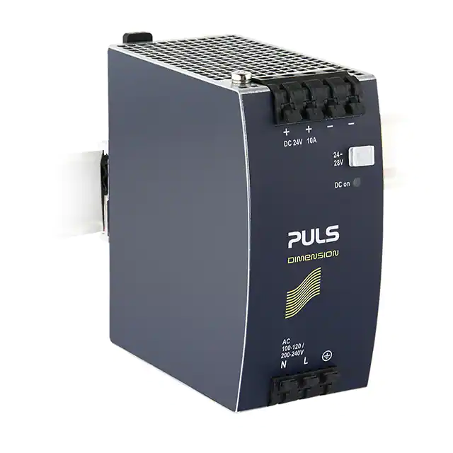
CS10.241, CS10.241-S1
24V, 10A, 240W SINGLE PHASE INPUT
CS-Series
POWER SUPPLY
▪
▪
▪
▪
▪
▪
▪
▪
▪
PRODUCT DESCRIPTION
AC 100-120 / 200-240V Auto-select Input
Width only 60mm
Optional with Spring-clamp Terminals (CS10.241-S1)
Efficiency up to 91.6%
Easy Fuse Breaking due to High Overload Peak Current
20% Output Power Reserves (PowerBoost)
Full Power Between -25°C and +60°C
Minimal Inrush Current Surge
3 Year Warranty
SHORT-FORM DATA
The DIMENSION CS-Series units are cost optimized power
supplies without compromising quality, reliability and
performance. The CS-Series is part of the DIMENSION power
supply family, existing alongside the high featured Q-Series.
The CS10.241 includes all the essential basic functions. The
devices also offer PowerBoost: Power reserves of 20%, which
may even be used continuously at temperatures up to +45°C.
The most important features are the small size, high efficiency
and the wide temperature range.
The Auto-select input makes worldwide installation and usage
very simple. Defects or system failures caused by wrongly set
switches cannot occur.
High immunity to transients and power surges as well as low
electromagnetic emission and a large international approval
package for a variety of applications makes this unit suitable for
nearly every situation.
ORDER NUMBERS
Output voltage
Adjustment range
Output current
PowerBoost
Output ripple
AC Input voltage
Mains frequency
AC Input current
DC Input voltage
Power factor
AC Inrush current
Efficiency
Losses
Temperature range
Hold-up time
Dimensions
Weight
DC 24V
24 - 28V
10A
up to +60°C ambient
8.6A
at +70°C ambient
Derate linearly between +60°C and +70°C
12A
up to +45°C ambient
Linear decrease to nominal power
between +45°C and +60°C
< 50mVpp
20Hz to 20MHz
AC 100-120V /
±10%
200-240V
Auto-select input
50-60Hz
±6%
3.73 / 2.23A
at 120 / 230Vac
not allowed
0.59 / 0.51
at 120 / 230Vac
3 / 3A peak
at 120 / 230Vac
91.0 / 91.6%
at 120 / 230Vac
23.7 / 22.0W
at 120 / 230Vac
-25°C to +70°C
operational
46 / 47ms
at 120 / 230Vac
60x124x117mm
WxHxD
700g
MAIN APPROVALS
Power Supply
CS10.241
CS10.241-S1
24-28V Standard unit
Version with quickconnect spring-clamp
terminals
Accessory
ZM1.WALL
ZM13.SIDE
YRM2.DIODE
YR40.241
Wall mount bracket
Side mount bracket
Redundancy module
Redundancy module
For details and the complete approval list, see chapter 18.
UL 508
UL 60950-1
Marine
Marine
Aug. 2022 / Rev. 2.1 DS-CS10.241-EN
All parameters are specified at 24V, 10A, 230Vac, 50Hz, 25°C ambient and after a 5 minutes run-in time unless otherwise noted.
www.pulspower.com Phone +49 89 9278 0 Germany
Class I Div 2
1/27
�CS10.241, CS10.241-S1
24V, 10A, 240W SINGLE PHASE INPUT
CS-Series
INDEX
Page
1.
2.
3.
4.
5.
6.
7.
8.
9.
10.
11.
12.
13.
14.
15.
16.
17.
18.
19.
20.
Intended Use ................................................................ 3
Installation Instructions ................................................ 3
AC-Input ....................................................................... 5
DC-Input ....................................................................... 7
Input Inrush Current ..................................................... 7
Output .......................................................................... 8
Hold-up Time ................................................................ 9
Efficiency and Power Losses ....................................... 10
Lifetime Expectancy and MTBF .................................. 11
Functional Diagram .................................................... 11
Terminals and Wiring ................................................. 12
Front Side and User Elements .................................... 13
EMC ............................................................................ 14
Environment ............................................................... 15
Protection Features .................................................... 16
Safety Features........................................................... 16
Dielectric Strength ...................................................... 17
Approved, Fulfilled or Tested Standards .................... 18
Regulatory Product Compliance ................................. 19
Physical Dimensions and Weight ................................ 20
Page
21. Accessories................................................................. 21
21.1. ZM1.WALL - Wall Mounting Bracket ................ 21
21.2. ZM13.SIDE - Side Mounting Bracket................. 21
21.3. YRM2.DIODE - Redundancy Modules ............... 22
21.4. YR40.241 - Redundancy Modules..................... 22
22. Application Notes....................................................... 23
22.1. Peak Current Capability .................................... 23
22.2. Back-feeding Loads .......................................... 24
22.3. External Input Protection ................................. 24
22.4. Output Circuit Breakers .................................... 24
22.5. Parallel Use to Increase Output Power ............ 25
22.6. Parallel Use for Redundancy ............................ 25
22.7. Series Operation............................................... 25
22.8. Inductive and Capacitive Loads ........................ 25
22.9. Charging of Batteries ........................................ 25
22.10. Operation on Two Phases ................................ 26
22.11. Use in a Tightly Sealed Enclosure ..................... 26
22.12. Mounting Orientations ..................................... 27
The information presented in this document is believed to be accurate and reliable and may change without notice.
No part of this document may be reproduced or utilized in any form without permission in writing from the publisher.
TERMINOLOGY, ABREVIATIONS AND DEFINITIONS
PE and
symbol
PE is the abbreviation for Protective Earth and has the same meaning as the symbol
.
Earth, Ground
This document uses the term “earth” which is the same as the U.S. term “ground”.
t.b.d.
To be defined, value or description will follow later.
AC 230V
A figure displayed with the AC or DC before the value represents a nominal voltage with standard tolerances
(usually ±15%) included.
E.g.: DC 12V describes a 12V battery disregarding whether it is full (13.7V) or flat (10V)
230Vac
A figure with the unit (Vac) at the end is a momentary figure without any additional tolerances included.
50Hz vs. 60Hz
As long as not otherwise stated, AC 100V and AC 230V parameters are valid at 50Hz mains frequency. AC
120V parameters are valid for 60Hz mains frequency.
may
A key word indicating flexibility of choice with no implied preference.
shall
A key word indicating a mandatory requirement.
should
A key word indicating flexibility of choice with a strongly preferred implementation.
Aug. 2022 / Rev. 2.1 DS-CS10.241-EN
All parameters are specified at 24V, 10A, 230Vac, 50Hz, 25°C ambient and after a 5 minutes run-in time unless otherwise noted.
www.pulspower.com Phone +49 89 9278 0 Germany
2/27
�CS10.241, CS10.241-S1
24V, 10A, 240W SINGLE PHASE INPUT
CS-Series
1. INTENDED USE
This device is designed for installation in an enclosure and is intended for commercial use, such as in industrial control, process control,
monitoring, measurement equipment or the like.
Do not use this device in equipment, where malfunctioning may cause severe personal injury or threaten human life without additional
appropriate safety devices, that are suited for the end-application.
If this device is used in a manner outside of its specification, the protection provided by the device may be impaired.
Without additional measures to reduce the harmonic input current (PFC), the power supply is not suited to be connected to the public
mains system in residential, commercial and light-industrial environments. No additional measures are necessary for use in industrial
environments. Exceptions for various countries outside the European Union exist and can be determined locally.
2. INSTALLATION INSTRUCTIONS
WARNING
-
Risk of electrical shock, fire, personal injury or death.
Turn power off before working on the device and protect against inadvertent re-powering.
Do not open, modify or repair the device.
Use caution to prevent any foreign objects from entering into the housing.
Do not use in wet locations or in areas where moisture or condensation can be expected.
Do not touch during power-on, and immediately after power-off. Hot surface may cause burns.
Obey the following installation instructions:
This device may only be installed and put into operation by qualified personnel.
This device does not contain serviceable parts. The tripping of an internal fuse is caused by an internal defect.
If damage or malfunction should occur during installation or operation, immediately turn power off and send unit to the factory for
inspection.
Install device in an enclosure providing protection against electrical, mechanical and fire hazards.
Install the device onto a DIN rail according to EN 60715 with the input terminals on the bottom of the device. Other mounting
orientations require a reduction in output current.
Make sure that the wiring is correct by following all local and national codes. Use appropriate copper cables that are designed for a
minimum operating temperature of 60°C for ambient temperatures up to +45°C, 75°C for ambient temperatures up to +60°C and 90°C
for ambient temperatures up to +70°C.
Ensure that all strands of a stranded wire enter the terminal connection. Use ferrules for wires on the input terminals. Unused screw
terminals should be securely tightened.
The device is designed for pollution degree 2 areas in controlled environments. No condensation or frost is allowed.
The enclosure of the device provides a degree of protection of IP20.The housing does not provide protection against spilled liquids.
The device is designed for overvoltage category II zones. Below 2000m altitude the device is tested for impulse withstand voltages up to
4kV, which corresponds to OVC III according to IEC 60664-1.
The device is designed as “Class of Protection I” equipment according to IEC 61140. Do not use without a proper PE (Protective Earth)
connection.
The device is suitable to be supplied from TN, TT and IT mains networks. The continuous voltage between the input terminals and the PE
potential must not exceed 300Vac.
A disconnecting means shall be provided for the input of the device.
The device is designed for convection cooling and does not require an external fan. Do not obstruct airflow and do not cover ventilation
grid!
Aug. 2022 / Rev. 2.1 DS-CS10.241-EN
All parameters are specified at 24V, 10A, 230Vac, 50Hz, 25°C ambient and after a 5 minutes run-in time unless otherwise noted.
www.pulspower.com Phone +49 89 9278 0 Germany
3/27
�CS10.241, CS10.241-S1
24V, 10A, 240W SINGLE PHASE INPUT
CS-Series
The device is designed for altitudes up to 5000m. Above 2000m a reduction in output current is required.
Keep the following minimum installation clearances: 40mm on top, 20mm on the bottom, 5mm left and right side. Increase the 5mm to
15mm in case the adjacent device is a heat source. When the device is permanently loaded with less than 50%, the 5mm can be reduced
to zero.
The device is designed, tested and approved for branch circuits up to 20A without additional protection device. If an external fuse is
utilized, do not use circuit breakers smaller than 10A B- or 6A C-Characteristic to avoid a nuisance tripping of the circuit breaker.
The maximum surrounding air temperature is +70°C. The operational temperature is the same as the ambient or surrounding air
temperature and is defined 2cm below the device.
The device is designed to operate in areas between 5% and 95% relative humidity.
Installation Instructions for Hazardous Location Areas
The device is suitable for use in Class I Division 2 Groups A, B, C, D locations.
Substitution of components may impair suitability for this environment.
Do not disconnect the device or operate the voltage adjustment unless power has been switched off or the area is known to be nonhazardous.
Aug. 2022 / Rev. 2.1 DS-CS10.241-EN
All parameters are specified at 24V, 10A, 230Vac, 50Hz, 25°C ambient and after a 5 minutes run-in time unless otherwise noted.
www.pulspower.com Phone +49 89 9278 0 Germany
4/27
�CS10.241, CS10.241-S1
24V, 10A, 240W SINGLE PHASE INPUT
CS-Series
3. AC-INPUT
AC input
nom.
Allowed voltage L or N to earth
Input frequency
Turn-on voltage
Shut-down voltage
External input protection
AC 100-120V /
Auto-select input
200-240V ±10%
TN, TT or IT
90-132Vac
lower input voltage range
180-264Vac
upper input voltage range
85- 90Vac
short-term or with reduced output current, see Fig. 3-5
264-300Vac
max. 500ms
no harm to the power supply with input voltages between 132 and 180Vac
max.
300Vac
continuous, according to IEC 62103
nom.
50–60Hz
±6%
typ.
80Vac
steady-state value, see Fig. 3-1
typ.
75Vac
steady-state value, see Fig. 3-1
See recommendations in chapter 22.3.
Input current
Power factor*)
Crest factor**)
Start-up delay
Rise time
typ.
typ.
typ.
typ.
typ.
AC 100V
4.34A
0.61
2.6
700ms
35ms
AC 120V
3.73A
0.59
2.8
800ms
35ms
AC 230V
2.23A
0.51
3.3
850ms
35ms
typ.
75ms
75ms
75ms
max.
100mV
100mV
100mV
Mains network systems
AC input range
Turn-on overshoot
at 24V, 10A, see Fig. 3-3
at 24V, 10A, see Fig. 3-4
at 24V, 10A
see Fig. 3-2
at 24V, 10A const. current load, 0mF
load capacitance, see Fig. 3-2
at 24V, 10A const. current load, 10mF
load capacitance,, see Fig. 3-2
see Fig. 3-2
*) The power factor is the ratio of the true (or real) power to the apparent power in an AC circuit.
**) The crest factor is the mathematical ratio of the peak value to RMS value of the input current waveform.
Rated input ranges
Turn-on
Shut -dow n
POUT
Lower
range
Fig. 3-2 Turn-on behavior, definitions
max.
500ms
Upper
range
Output
Voltage
VIN
(85) 90
Input
Voltage
132
180
- 5%
Start-up
delay
Rise
Time
Overshoot
Fig. 3-1 Input voltage ranges
264 300Vac
Aug. 2022 / Rev. 2.1 DS-CS10.241-EN
All parameters are specified at 24V, 10A, 230Vac, 50Hz, 25°C ambient and after a 5 minutes run-in time unless otherwise noted.
www.pulspower.com Phone +49 89 9278 0 Germany
5/27
�CS10.241, CS10.241-S1
24V, 10A, 240W SINGLE PHASE INPUT
CS-Series
Fig. 3-3 Input current vs. output load at 24V
Fig. 3-4 Power factor vs. output load
Input Current, typ.
Power Factor, typ.
6A
0.65
(a)
5
a) 100Vac
b) 120Vac
c) 230Vac
4
3
(b)
(c)
0.60
(a)
(b)
0.55
(c)
0.50
a) 100Vac
b) 120Vac
c) 230Vac
0.45
2
0.40
1
Output Current
0
2
3
4
5
6
7
8
9 10 11 12A
Output Current
0.35
2
3
4
5
6
7
8
9 10 11 12A
Fig. 3-5 Input voltage derating
Allowable Output Current at 85Vac
12A
B
10
A
8
6
A... at 85Vac, continuous
B... short term
4
2
Ambient Temperature
0
30
40
50
60
70°C
Aug. 2022 / Rev. 2.1 DS-CS10.241-EN
All parameters are specified at 24V, 10A, 230Vac, 50Hz, 25°C ambient and after a 5 minutes run-in time unless otherwise noted.
www.pulspower.com Phone +49 89 9278 0 Germany
6/27
�CS10.241, CS10.241-S1
24V, 10A, 240W SINGLE PHASE INPUT
CS-Series
4. DC-INPUT
Do not operate this power supply with DC-input voltage. Use the CP10.241 or CP10.242 units instead.
5. INPUT INRUSH CURRENT
After turn-on of the input voltage, an active inrush limitation circuit limits the input inrush current. Virtually no input inrush current is
generated.
The charging current into the EMI suppression capacitors is disregarded in the first microseconds after switch-on.
Inrush current
Inrush energy
AC 100V
10Apeak
3Apeak
1A2s
max.
typ.
max.
AC 120V
10Apeak
3Apeak
1A2s
AC 230V
10Apeak
3Apeak
1A2s
temperature independent
temperature independent
temperature independent
Fig. 5-1 Typical input inrush current behavior
Input Current
Input Voltage
Input:
Output:
Ambient:
230Vac
24V, 10A
25°C
Upper curve:
Medium curve:
Lower curve:
Time scale:
Input current (10A / DIV)
Input voltage (500V / DIV)
Output voltage (20V / DIV)
100ms / DIV
Output
Voltage
Aug. 2022 / Rev. 2.1 DS-CS10.241-EN
All parameters are specified at 24V, 10A, 230Vac, 50Hz, 25°C ambient and after a 5 minutes run-in time unless otherwise noted.
www.pulspower.com Phone +49 89 9278 0 Germany
7/27
�CS10.241, CS10.241-S1
24V, 10A, 240W SINGLE PHASE INPUT
CS-Series
6. OUTPUT
Output voltage
Adjustment range
nom.
24V
24-28V
guaranteed
max.
30V***)
at clockwise end position of potentiometer
typ.
24.1V
±0.2%, at full load, cold unit
max.
70mV
90-132 / 180-300Vac
max.
100mV
static value, 0A → 10A; see Fig. 6-1
max.
50mVpp
20Hz to 20MHz, 50Ohm
nom.
10A
at 24V and up to +60°C ambient temperature, see Fig. 6-1
nom.
7.5A
at 24V and +70°C ambient temperature
nom.
8.6A
at 28V and up to +60°C ambient temperature, see Fig. 6-1
nom.
6.5A
at 28V and +70°C ambient temperature
Derate linearly between +60°C and +70°C, see chapter 14
nom.
12A
at 24V and up to +45°C ambient temperature, see Fig. 14.1
nom.
10.3A
at 28V and up to +45°C ambient temperature, see Fig. 14.1
PowerBoost decreases linearly to nominal power between +45°C and +60°C, see chapter 14
Factory settings
Line regulation
Load regulation
Ripple and noise voltage
Output current
PowerBoost*)
Overload behavior
Short-circuit current
Output capacitance
*)
**)
***)
min.
max.
continuous current
14A**)
18A**)
see Fig. 6-1
load impedance 2000m, see Fig. 14-2
IEC 62103, EN 50178, altitudes up to 2000m
altitudes from 2000m to 6000m
IEC 62103, EN 50178, not conductive
15W/1000m or 5K/1000m
III
II
2
Degree of pollution
*) Operational temperature is the same as the ambient or surrounding temperature and is defined as the air temperature 2cm below the unit.
**) Do not energize while condensation is present
***) Tested in combination with DIN rails according to EN 60715 with a height of 15mm and a thickness of 1.3mm and standard orientation.
Fig. 14-1 Output current vs. ambient temp.
(Inom 10A; Iout with PowerBoost = 12A)
Fig. 14-2 Output current vs. altitude
Allowable Output Current at 24V
Allowable Output Current at 24V
12A
A
8
10
C
B
A
8
A...90-132/ 180-264Vac, continuous
B... short term
4
6
A... Tamb < 60°C
B... Tamb < 50°C
C... Tamb < 40°C
D... Short t erm
4
2
0
-25
D
B
10
6
12A
2
Ambient Temperature
0
20
40
Altitude
0
60 70°C
0
2000
4000
Aug. 2022 / Rev. 2.1 DS-CS10.241-EN
All parameters are specified at 24V, 10A, 230Vac, 50Hz, 25°C ambient and after a 5 minutes run-in time unless otherwise noted.
www.pulspower.com Phone +49 89 9278 0 Germany
6000m
15/27
�CS10.241, CS10.241-S1
24V, 10A, 240W SINGLE PHASE INPUT
CS-Series
15. PROTECTION FEATURES
Output protection
Output over-voltage protection
Degree of protection
Penetration protection
Over-temperature protection
Input transient protection
Internal input fuse
*)
Electronically protected against overload, no-load and short-circuits*)
typ. 35Vdc
In case of an internal power supply defect, a redundant circuit
limits the maximum output voltage. The output shuts down and
max. 39Vdc
automatically attempts to restart.
IP 20
EN/IEC 60529
Caution: For use in a controlled environment according to CSA
22.2 No 107.1-01.
> 3.5mm
e.g. screws, small parts
yes
Output shut-down with automatic restart
MOV (Metal Oxide Varistor)
included
not user replaceable
In case of a protection event, audible noise may occur.
16. SAFETY FEATURES
Input / output separation*)
Class of protection
Isolation resistance
PE resistance
Touch current (leakage current)
SELV
PELV
double or reinforced insulation
I
> 5MOhm
< 0.1Ohm
typ. 0.36mA / 0.91mA
typ. 0.50mA / 1.25mA
typ. 0.64mA / 1.59mA
max. 0.45mA / 1.13mA
max. 0.62mA / 1.55mA
max. 0.85mA / 2.11mA
IEC/EN 60950-1
IEC/EN 60204-1, EN 50178, IEC 62103, IEC 60364-4-41
PE (Protective Earth) connection required
input to output, 500Vdc
between housing and PE terminal
100Vac, 50Hz, TN-,TT-mains / IT-mains
120Vac, 60Hz, TN-,TT-mains / IT-mains
230Vac, 50Hz, TN-,TT-mains / IT-mains
110Vac, 50Hz, TN-,TT-mains / IT-mains
132Vac, 60Hz, TN-,TT-mains / IT-mains
264Vac, 50Hz, TN-,TT-mains / IT-mains
Aug. 2022 / Rev. 2.1 DS-CS10.241-EN
All parameters are specified at 24V, 10A, 230Vac, 50Hz, 25°C ambient and after a 5 minutes run-in time unless otherwise noted.
www.pulspower.com Phone +49 89 9278 0 Germany
16/27
�CS10.241, CS10.241-S1
24V, 10A, 240W SINGLE PHASE INPUT
CS-Series
17. DIELECTRIC STRENGTH
The output voltage is floating and has no ohmic connection to the ground. Type and factory tests are conducted by the manufacturer.
Field tests may be conducted in the field using the appropriate test equipment which applies the voltage with a slow ramp (2s up and 2s
down). Connect all input-terminals together as well as all output poles before conducting the test. When testing, set the cut-off current
settings to the value in the table below.
Type test
60s
A
2500Vac
B
3000Vac
C
500Vac
Factory test
5s
2500Vac
2500Vac
500Vac
Field test
5s
2000Vac
2000Vac
500Vac
Cut-off current setting
> 15mA
> 15mA
> 20mA
Fig. 17-1 Dielectric strength
Input
L
N
B
Earth, PE
Output
+
A
C
To fulfil the PELV requirements according to EN60204-1 § 6.4.1, we
recommend that either the + pole, the – pole or any other part of the
output circuit shall be connected to the protective earth system. This helps
to avoid situations in which a load starts unexpectedly or can not be
switched off when unnoticed earth faults occur.
Aug. 2022 / Rev. 2.1 DS-CS10.241-EN
All parameters are specified at 24V, 10A, 230Vac, 50Hz, 25°C ambient and after a 5 minutes run-in time unless otherwise noted.
www.pulspower.com Phone +49 89 9278 0 Germany
17/27
�CS10.241, CS10.241-S1
24V, 10A, 240W SINGLE PHASE INPUT
CS-Series
18. APPROVED, FULFILLED OR TESTED STANDARDS
UL 508
IEC 61010-2-201
IEC 60950-1
UL 60950-1
Class I Div 2
Marine (DNV)
Marine (ABS)
ISA-71.04 G3
(only CS10.241)
VDMA 24364
UL Certificate
Listed equipment for category NMTR - Industrial Control Equipment
Applicable for US and Canada
E-File: E198865
Manufacturer's Declaration
Electrical Equipment for Measurement, Control and Laboratory Use Particular requirements for control equipment
CB Scheme Certificate
General safety requirements for Information Technology Equipment (ITE)
UL Certificate
Recognized component for category QQGQ - Information Technology
Equipment (ITE)
Applicable for US and Canada
E-File: E137006
CSA Certificate
Power Supplies for Hazardous Location
Applicable for Canada and US
CSA Class: 5318-01 (Canada), 5318-81 (USA)
Temperature Code: T3
Groups: A, B, C and D
DNV Certificate
DNV Type approved product
Certificate: TAA00001ST
Temperature: Class B
Humidity: Class B
Vibration: Class C
EMC: Class A
Enclosure: Class A
ABS Design Assessment Certificate
ABS (American Bureau of Shipment) assessed product
Certificate: 17-HG1599236-PDA
Manufacturer's Declaration (Online Document)
Airborne Contaminants Corrosion Test
Severity Level: G3 Harsh
H2S: 100ppb
NOx: 1250ppb
Cl2: 20ppb
SO2: 300ppb
Test Duration: 3 weeks, which simulates a service life of 10 years.
Paint Wetting Impairment Substances Test (or LABS-Test)
Tested for Zone 2 and test class C1 according to VDMA 24364-C1-L/W for
solvents and water-based paints
Aug. 2022 / Rev. 2.1 DS-CS10.241-EN
All parameters are specified at 24V, 10A, 230Vac, 50Hz, 25°C ambient and after a 5 minutes run-in time unless otherwise noted.
www.pulspower.com Phone +49 89 9278 0 Germany
18/27
�CS10.241, CS10.241-S1
24V, 10A, 240W SINGLE PHASE INPUT
CS-Series
19. REGULATORY PRODUCT COMPLIANCE
EU Declaration of Conformity
REACH Regulation (EU)
WEEE Regulation
The CE mark indicates conformance with the
- EMC directive
- Low-voltage directive
- RoHS directive
Manufacturer's Declaration
EU regulation regarding the Registration, Evaluation, Authorisation and
Restriction of Chemicals (REACH) fulfilled.
EU Regulation (EC) 1907/2006.
Manufacturer's Declaration
EU Regulation on Waste Electrical and Electronic Equipment
Registered as business to business (B2B) products.
EU Regulation 2012/19/EU
Aug. 2022 / Rev. 2.1 DS-CS10.241-EN
All parameters are specified at 24V, 10A, 230Vac, 50Hz, 25°C ambient and after a 5 minutes run-in time unless otherwise noted.
www.pulspower.com Phone +49 89 9278 0 Germany
19/27
�CS10.241, CS10.241-S1
24V, 10A, 240W SINGLE PHASE INPUT
CS-Series
20. PHYSICAL DIMENSIONS AND WEIGHT
Width
Height
Depth
Weight
DIN rail
Housing material
Installation clearances
60mm
124mm
117mm
The DIN rail depth must be added to the unit depth to calculate the total required installation depth.
700g
Use 35mm DIN rails according to EN 60715 or EN 50022 with a height of 7.5 or 15mm.
Body: Aluminium alloy
Cover: Zinc-plated steel
See chapter 2
Fig. 20-1 Front view
CS10.241
CS10.241-S1
Fig. 20-2 Side view
Aug. 2022 / Rev. 2.1 DS-CS10.241-EN
All parameters are specified at 24V, 10A, 230Vac, 50Hz, 25°C ambient and after a 5 minutes run-in time unless otherwise noted.
www.pulspower.com Phone +49 89 9278 0 Germany
20/27
�CS10.241, CS10.241-S1
24V, 10A, 240W SINGLE PHASE INPUT
CS-Series
21. ACCESSORIES
21.1. ZM1.WALL - WALL MOUNTING BRACKET
This bracket is used to mount the power
supply onto a flat surface without utilizing a DIN rail.
21.2. ZM13.SIDE - SIDE MOUNTING BRACKET
This bracket is used to mount Dimension units sideways with or without utilizing a DIN rail. The two aluminum brackets and the black
plastic slider of the unit must be detached so that the steel brackets can be installed.
For sideway DIN rail mounting, the removed aluminum brackets and the black plastic slider need to be mounted on the steel bracket.
Side mounting with DIN rail brackets
Side mounting without DIN rail brackets
Aug. 2022 / Rev. 2.1 DS-CS10.241-EN
All parameters are specified at 24V, 10A, 230Vac, 50Hz, 25°C ambient and after a 5 minutes run-in time unless otherwise noted.
www.pulspower.com Phone +49 89 9278 0 Germany
21/27
�CS10.241, CS10.241-S1
24V, 10A, 240W SINGLE PHASE INPUT
CS-Series
21.3. YRM2.DIODE - REDUNDANCY MODULES
(2x 10A Inputs, 1x 20A output)
The YRM2.DIODE is a dual redundancy module, which can be used to build 1+1 and N+1
redundant systems. It is equipped with two input channels, which are individually decoupled by
utilizing diodes.
The YRM2.DIODE does not require an additional auxiliary voltage and is self-powered even in
case of a short circuit across the output.
The YRM2.DIODE has a monitoring circuit included and is the perfect solution when the power
supply has no DC-OK function. Two LEDs and two relay contacts signal when one of the two DCinput voltages is not in range due to a non-functioning or disconnected power supply.
Due to the compact design, the unit is very slender and only requires 32mm width on the DIN
rail.
21.4. YR40.241 - REDUNDANCY MODULES
(2x 20A input, 1x 40A output)
The YR40.241 is a dual redundancy module, which can be used to build redundant systems. It
is equipped with two input channels, which are individually decoupled by utilizing MOSFET
technology.
Using MOSFET instead of diodes reduces the heat generation and the voltage drop between
input and output. The YR40.241 does not require an additional auxiliary voltage and is selfpowered even in case of a short circuit across the output.
Due to the low power losses, the unit is very slender and only requires 36mm width on the DIN
rail.
Fig. 21-1 Typical 1+1 Redundant configuration for 10A load current
Failure
Monitor
+ + - 24V, 10A
+ -+ IN 1 IN 2 IN 1IN 2
+ + - 24V, 10A
CS10
Power Supply
YRM2.DIODE
CS10
Power Supply
L N PE
OUT
+ -
L N PE
optional
I
I
10A
Load
L
N
PE
Aug. 2022 / Rev. 2.1 DS-CS10.241-EN
All parameters are specified at 24V, 10A, 230Vac, 50Hz, 25°C ambient and after a 5 minutes run-in time unless otherwise noted.
www.pulspower.com Phone +49 89 9278 0 Germany
22/27
�CS10.241, CS10.241-S1
24V, 10A, 240W SINGLE PHASE INPUT
CS-Series
22. APPLICATION NOTES
22.1. PEAK CURRENT CAPABILITY
The unit can deliver peak currents (up to several milliseconds) which are higher than the specified short term currents.
This helps to start current demanding loads. Solenoids, contactors and pneumatic modules often have a steady state coil and a pick-up
coil. The inrush current demand of the pick-up coil is several times higher than the steady-state current and usually exceeds the nominal
output current (including the PowerBoost). The same situation applies when starting a capacitive load.
The peak current capability also ensures the safe operation of subsequent circuit breakers of load circuits. The load branches are often
individually protected with circuit breakers or fuses. In case of a short or an overload in one branch circuit, the fuse or circuit breaker
need a certain amount of over-current to open in a timely manner. This avoids voltage loss in adjacent circuits.
The extra current (peak current) is supplied by the power converter and the built-in large sized output capacitors of the power supply.
The capacitors get discharged during such an event, which causes a voltage dip on the output. The following two examples show typical
voltage dips:
Fig. 22-1 Peak load with 2x the nominal current for 50ms,
typ.
Output
Voltage
24V
Fig. 22-2 Peak load with 5x the nominal current for 5ms,
typ.
24V
Output
Voltage
50A
18.5V
20A
12V
Output
Current
0A
1ms/DIV
10ms/DIV
20A Peak load (resistive) for 50ms
Output voltage dips from 24V to 18.5V.
Peak current voltage dips
Output
Current
0A
typ.
typ.
typ.
50A Peak load (resistive) for 5ms
Output voltage dips from 24V to 12V.
from 24V to 18.5V
from 24V to 17V
from 24V to 12V
at 20A for 50ms, resistive load
at 50A for 2ms, resistive load
at 50A for 5ms, resistive load
Aug. 2022 / Rev. 2.1 DS-CS10.241-EN
All parameters are specified at 24V, 10A, 230Vac, 50Hz, 25°C ambient and after a 5 minutes run-in time unless otherwise noted.
www.pulspower.com Phone +49 89 9278 0 Germany
23/27
�CS10.241, CS10.241-S1
24V, 10A, 240W SINGLE PHASE INPUT
CS-Series
22.2. BACK-FEEDING LOADS
Loads such as decelerating motors and inductors can feed voltage back to the power supply. This feature is also called return voltage
immunity or resistance against Back- E.M.F. (Electro Magnetic Force).
This power supply is resistant and does not show malfunctioning when a load feeds back voltage to the power supply. It does not matter
whether the power supply is on or off.
The maximum allowed feed-back-voltage is 35Vdc. The absorbing energy can be calculated according to the built-in large sized output
capacitor which is specified in chapter 6.
22.3. EXTERNAL INPUT PROTECTION
The unit is tested and approved for branch circuits up to 20A. An external protection is only required if the supplying branch has an
ampacity greater than this. Check also local codes and local requirements. In some countries local regulations might apply.
If an external fuse is necessary or utilized, minimum requirements need to be considered to avoid nuisance tripping of the circuit
breaker. A minimum value of 10A B- or 6A C-Characteristic breaker should be used.
22.4. OUTPUT CIRCUIT BREAKERS
Standard miniature circuit breakers (MCB’s or UL 1077 circuit breakers) are commonly used for AC-supply systems and may also be used
on 24V branches.
MCB’s are designed to protect wires and circuits. If the ampere value and the characteristics of the MCB are adapted to the wire size
that is used, the wiring is considered as thermally safe regardless of whether the MCB opens or not.
To avoid voltage dips and under-voltage situations in adjacent 24V branches which are supplied by the same source, a fast (magnetic)
tripping of the MCB is desired. A quick shutdown within 10ms is necessary corresponding roughly to the ride-through time of PLC's. This
requires power supplies with high current reserves and large output capacitors. Furthermore, the impedance of the faulty branch must
be sufficiently small in order for the current to actually flow. The best current reserve in the power supply does not help if Ohm’s law
does not permit current flow. The following table has typical test results showing which B- and C-Characteristic MCBs magnetically trip
depending on the wire cross chapter and wire length.
Fig. 22-3 Test circuit
Power Supply
AC
MCB
+
Wire length
DC S1... Fault simulation switch
*)
Load
Maximal wire length*) for a fast (magnetic) tripping:
0.75mm²
1.0mm²
1.5mm²
C-2A
21m
26m
37m
2.5mm²
68m
+
C-3A
C-4A
15m
10m
21m
14m
30m
20m
51m
38m
-
C-6A
C-8A
C-10A
4m
1m
1m
6m
2m
2m
9m
4m
3m
16m
6m
4m
B-6A
B-10A
13m
10m
18m
5m
26m
9m
42m
11m
S1
Don’t forget to consider twice the distance to the load (or cable length) when calculating the total wire length (+ and – wire).
Aug. 2022 / Rev. 2.1 DS-CS10.241-EN
All parameters are specified at 24V, 10A, 230Vac, 50Hz, 25°C ambient and after a 5 minutes run-in time unless otherwise noted.
www.pulspower.com Phone +49 89 9278 0 Germany
24/27
�CS10.241, CS10.241-S1
24V, 10A, 240W SINGLE PHASE INPUT
CS-Series
22.5. PARALLEL USE TO INCREASE OUTPUT POWER
The power supply shall not be used in parallel to increase the output current.
22.6. PARALLEL USE FOR REDUNDANCY
Power supplies can be paralleled for redundancy to gain higher system availability. Redundant systems require a certain amount of extra
power to support the load in case one power supply unit fails. The simplest way is to put two power supplies in parallel. This is called a
1+1 redundancy. In case one power supply unit fails, the other one is automatically able to support the load current without any
interruption, see also chapter 22.5.
Please note: This simple way to build a redundant system does not cover failures such as an internal short circuit in the secondary side
of the power supply. In such a case, the defective unit becomes a load for the other power supplies and the output voltage can no
longer be maintained. This can be avoided by utilizing redundancy modules, which have decoupling devices (diodes or MOSFETs)
included. Further information and wiring configurations can be found in chapter 21.3.
Recommendations for building redundant power systems:
a)
b)
c)
Use separate input fuses for each power supply.
Monitor the individual power supply units.
Therefore, use the DC-OK relay contact of the YRM2.DIODE.
It is desirable to set the output voltages of all units to the same value (± 100mV) or leave it at the factory setting.
22.7. SERIES OPERATION
Unit A
Power supplies of the same type can be connected in series for higher output voltages.
It is possible to connect as many units in series as needed, providing the sum of the
output voltage does not exceed 150Vdc. Voltages with a potential above 60Vdc are no
longer SELV and can be dangerous. Such voltages must be installed with a protection
against touching.
AC
Earthing of the output is required when the sum of the output voltage is above 60Vdc.
AC
DC
+
+
Unit B
Avoid return voltage (e.g. from a decelerating motor or battery) which is applied to the
output terminals.
DC
Load
+
-
Earth
(see notes)
Keep an installation clearance of 15mm (left / right) between two power supplies and
avoid installing the power supplies on top of each other. Do not use power supplies in series in mounting orientations other than the
standard mounting orientation (input terminals on bottom of the unit).
Pay attention that leakage current, EMI, inrush current, harmonics will increase when using multiple power supplies.
22.8. INDUCTIVE AND CAPACITIVE LOADS
The unit is designed to supply any kind of loads, including capacitive and inductive loads.
22.9. CHARGING OF BATTERIES
The power supply shall not be used to charge batteries. Choose power supplies of the QS-Series or CP-Series for charging batteries.
Aug. 2022 / Rev. 2.1 DS-CS10.241-EN
All parameters are specified at 24V, 10A, 230Vac, 50Hz, 25°C ambient and after a 5 minutes run-in time unless otherwise noted.
www.pulspower.com Phone +49 89 9278 0 Germany
25/27
�CS10.241, CS10.241-S1
24V, 10A, 240W SINGLE PHASE INPUT
CS-Series
22.10. OPERATION ON TWO PHASES
The power supply can also be used on two-phases of a three-phase-system. A phase-to-phase connection is allowed as long as the
supplying voltage is below 240V+10%.
Power Supply
240V +10% max.
L1
L3
22.11. USE IN A TIGHTLY SEALED ENCLOSURE
AC
L
Fuse
L2
internal
fuse
N
PE
DC
When the power supply is installed in a tightly sealed enclosure, the temperature inside
the enclosure will be higher than outside. In such situations, the inside temperature defines the ambient temperature for the power
supply.
The following measurement results can be used as a reference to estimate the temperature rise inside the enclosure.
The power supply is placed in the middle of the box, no other heat producing items are inside the box
Enclosure:
Load:
Input:
Temperature inside enclosure:
Temperature outside enclosure:
Temperature rise:
25.6K
Rittal Typ IP66 Box PK 9519 100, plastic, 180x180x165mm
24V, 8A; (=80%) load is placed outside the box
230Vac
48.9°C (in the middle of the right side of the power supply with a distance of 2cm)
23.3°C
Aug. 2022 / Rev. 2.1 DS-CS10.241-EN
All parameters are specified at 24V, 10A, 230Vac, 50Hz, 25°C ambient and after a 5 minutes run-in time unless otherwise noted.
www.pulspower.com Phone +49 89 9278 0 Germany
26/27
�CS10.241, CS10.241-S1
24V, 10A, 240W SINGLE PHASE INPUT
CS-Series
22.12. MOUNTING ORIENTATIONS
Mounting orientations other than the input terminals on the bottom require a reduction in continuous output power or a limitation in
the maximum allowed ambient temperature. The amount of reduction influences the lifetime expectancy of the power supply.
Therefore, two different derating curves for continuous operation can be found below:
Curve A1 Recommended output current.
Curve A2 Max allowed output current (results in approximately half the lifetime expectancy of A1).
Fig. 22-4
Mounting
Orientation A
(Standard
orientation)
Output Current
12A
OUTPUT
A1
9
Power
Supply
9
3
Ambient Temperature
0
INPUT
10
Fig. 22-5
Mounting
Orientation B
(Upside down)
20
30
40
50
60°C
Output Current
INPUT
12A
9
A2
A1
Pow er
Supply
6
3
Ambient Temperature
OUTPUT
0
10
Fig. 22-6
Mounting
Orientation C
(Table-top
mounting)
20
30
40
50
60°C
Output Current
12A
9
A2
6
A1
3
Ambient Temperature
0
10
40
50
60°C
12A
OUTPUT
Pow er
Supply
9
A2
A1
6
3
Ambient Temperature
0
10
20
30
40
50
60°C
Output Current
9
INPUT
Pow er
Supply
12A
OUTPUT
Fig. 22-8
Mounting
Orientation E
(Horizontal ccw)
30
Output Current
INPUT
Fig. 22-7
Mounting
Orientation D
(Horizontal cw)
20
A2
A1
6
3
Ambient Temperature
0
10
20
30
40
50
60°C
Aug. 2022 / Rev. 2.1 DS-CS10.241-EN
All parameters are specified at 24V, 10A, 230Vac, 50Hz, 25°C ambient and after a 5 minutes run-in time unless otherwise noted.
www.pulspower.com Phone +49 89 9278 0 Germany
27/27
�


 工商网监
湘ICP备2023018690号
工商网监
湘ICP备2023018690号
