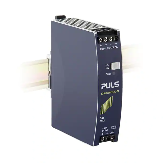
CD5.121
DC/DC Converter 12V, 8A
CD-Series
DC/DC CONVERTER
24V DC-Input
Isolated 12Vdc Output
Efficiency up to 88.2%
Width only 32mm
20% Output Power Reserves
Full Power Between -25°C and +60°C
Soft-start Function Included
Minimal Inrush Current Surge
Reverse Input Polarity Protection
3 Year Warranty
PRODUCT DESCRIPTION
SHORT-FORM DATA
The Dimension CD-Series offer DIN rail DC/DC converters
in the 92-120W output power range in a very compact
housing. These DC/DC converters are allowed to run
with a battery or similar sources.
Output voltage
Adjustment range
Output current
The CD5.121 converts a 24V voltage to a 12V voltage.
The CD5.121 includes all the essential basic functions
and has a power reserve of 20% included. This extra
power can be used continuously up to +45°C.
The output is electrically isolated from the input in a
safe way. The input is protected against reversed
voltages and contains a soft start function.
CD-Series
Related products
24V->24V
CD5.051
24V->5V
CD5.121
24V->12V
CD5.243
12V->24V
CD5.241
CD5.242
SLD2.100
24V->5V
CD5.241-L1
CD5.241-S1
48V->24V
24V->24V, NEC Class 2,
Spring-clamp-terminals,
24V->24V,
Spring-clamp-terminals,
Input-low, DC-OK signals
ORDER NUMBERS
DC 12V
12 - 15V
8 – 6.4A
9.6 – 7.7A
Output power
96W
115W
Output ripple
< 75mVpp
Input voltage
DC 24V
Input voltage range 18 to 32.4Vdc
14.4 to 18Vdc
Input current
typ. 4.6A
Input inrush current typ. 1.2A peak
Efficiency
88.2%
Losses
12.8W
Temperature range -25°C to +70°C
Derating
2.5W/°C
Hold-up time
typ. 7ms
Dimensions
32x124x102mm
Weight
425g / 0.94lb
ambient 5MOhm
input to output, 500Vdc
< 0.1Ohm
between housing and Chassis Ground terminal
The leakage current which is produced by the DC/DC converter itself depends on the
input voltage ripple and need to be investigated in the final application.
For a smooth DC input voltage, the produced leakage current is less than 100µA.
provided, that the input voltage meets the requirements of chapter 2.
Jul. 2021 / Rev. 1.8 DS-CD5.121-EN
All parameters are specified at 12V, 8A, 24Vdc input voltage, 25°C ambient and after a 5 minutes run-in time unless otherwise noted.
www.pulspower.com Phone +49 89 9278 0
Germany
15/26
�CD5.121
DC/DC Converter 12V, 8A
CD-Series
17. DIELECTRIC STRENGTH
The output voltage is floating and has no ohmic connection to the ground.
Type and factory tests are conducted by the manufacturer. Field tests may be conducted in the field using the
appropriate test equipment which applies the voltage with a slow ramp (2s up and 2s down). Connect all input
terminals together as well as all output poles before conducting the test. When testing, set the cut-off current settings
to the value in the table below.
Type test
60s
A
1500Vac
B
1500Vac
C
500Vac
Factory test
5s
1500Vac
1500Vac
500Vac
Field test
5s
1000Vac
1000Vac
500Vac
> 30mA
> 30mA
> 12mA
Fig. 17-1 Dielectric strength
Input
+
B
-
Output
A
Chassis
ground
+
C
-
Cut-off current setting
To fulfill the PELV requirements according to EN60204-1 § 6.4.1, we
recommend that either the + pole, the – pole or any other part of
the output circuit shall be connected to the protective earth
system. This helps to avoid situations in which a load starts
unexpectedly or can not be switched off when unnoticed earth
faults occur.
Jul. 2021 / Rev. 1.8 DS-CD5.121-EN
All parameters are specified at 12V, 8A, 24Vdc input voltage, 25°C ambient and after a 5 minutes run-in time unless otherwise noted.
www.pulspower.com Phone +49 89 9278 0
Germany
16/26
�CD5.121
DC/DC Converter 12V, 8A
CD-Series
18. APPROVED, FULFILLED OR TESTED STANDARDS
UL 508
IEC 60950-1
UL 60950-1
Class I Div 2
Class I Div 2
ATEX
IECEx
Marine (DNV)
UL Certificate
Listed equipment for category NMTR - Industrial Control
Equipment
Applicable for US and Canada
E-File: E198865
CB Scheme Certificate
General safety requirements for Information Technology
Equipment (ITE)
UL Certificate
Recognized component for category QQGQ - Information
Technology Equipment (ITE)
Applicable for US and Canada
E-File: E137006
CSA Certificate
Power Supplies for Hazardous Location
Applicable for Canada and US
CSA Class: 5318-01 (Canada), 5318-81 (USA)
Temperature Code: T4
Groups: A, B, C and D
UL Certificate
Listed equipment for category NRAD - Listed equipment
Industrial Control Equipment for Use in Hazardous Locations
Applicable for US and Canada
E-File: E327416
Temperature Code: T4
Groups: A, B, C and D
Agency Certificate (Bureau Veritas)
EN 60079-0 Explosive atmospheres - General requirements
EN 60079-7, EN 60079-15 Equipment protection by type of
protection "e" and "n"
Certificate: EPS 08 ATEX 1 142 X
Temperature Code: T4
Type of Protection: ec nC
IECEx Certificate
IEC 60079-0 Explosive atmospheres - General requirements
IEC 60079-15 Equipment protection by type of protection "n"
Certificate: IECEx EPS 14.0001X
Temperature Code: T4
Type of Protection: ec nC
DNV Certificate
DNV Type approved product
Certificate: TAA00001ST
Temperature: Class D
Humidity: Class B
Vibration: Class C
EMC: Class A
Enclosure: Class A
Jul. 2021 / Rev. 1.8 DS-CD5.121-EN
All parameters are specified at 12V, 8A, 24Vdc input voltage, 25°C ambient and after a 5 minutes run-in time unless otherwise noted.
www.pulspower.com Phone +49 89 9278 0
Germany
17/26
�CD5.121
DC/DC Converter 12V, 8A
CD-Series
Marine (ABS)
IEC 60068-2-60
ISA-71.04 G3
VDMA 24364
ABS Design Assessment Certificate
ABS (American Bureau of Shipment) assessed product
Certificate: 17-HG1599236-PD
Manufacturer's Declaration (Online Document)
Environmental Tests, Flowing Mixed Gas Corrosion Test
Test Ke - Method 4
H2S: 10ppb
NO2: 200ppb
Cl2: 10ppb
SO2: 200ppb
Test Duration: 3 weeks, which simulates a service life of at least
10 years.
Manufacturer's Declaration (Online Document)
Airborne Contaminants Corrosion Test
Severity Level: G3 Harsh
H2S: 100ppb
NOx: 1250ppb
Cl2: 20ppb
SO2: 300ppb
Test Duration: 3 weeks, which simulates a service life of at least
10 years
Paint Wetting Impairment Substances Test (or LABS-Test)
Tested for Zone 2 and test class C1 according to VDMA 24364C1-L/W for solvents and water-based paints
19. REGULATORY PRODUCT COMPLIANCE
EU Declaration of
Conformity
KC
REACH Directive
WEEE Directive
EAC TR Registration
The CE mark indicates conformance with the
- EMC directive
- ATEX directive
- RoHS directive
KC Registration
Korean registration of Broadcasting and Communication
Equipment
Registered under Clause 3, Article 58-2 of Radio Waves Act.
Manufacturer's Statement
EU-Directive regarding the Registration, Evaluation,
Authorization and Restriction of Chemicals
Manufacturer's Statement
EU-Regulation on Waste Electrical and Electronic Equipment
Registered in Germany as business to business (B2B) products.
EAC Certificate
EAC EurAsian Conformity - Registration Russia, Kazakhstan
and Belarus
8504408200, 8504409000
Jul. 2021 / Rev. 1.8 DS-CD5.121-EN
All parameters are specified at 12V, 8A, 24Vdc input voltage, 25°C ambient and after a 5 minutes run-in time unless otherwise noted.
www.pulspower.com Phone +49 89 9278 0
Germany
18/26
�CD5.121
CD-Series
DC/DC Converter 12V, 8A
20. PHYSICAL DIMENSIONS AND WEIGHT
Weight
DIN rail
Installation Clearances
425g / 0.94lb
Use 35mm DIN rails according to EN 60715 or EN 50022 with a height of 7.5 or 15mm.
The DIN rail depth must be added to the unit depth (102mm) to calculate the total required
installation depth.
See chapter 2
Fig. 20-1 Front view
Fig. 20-2 Side view
Jul. 2021 / Rev. 1.8 DS-CD5.121-EN
All parameters are specified at 12V, 8A, 24Vdc input voltage, 25°C ambient and after a 5 minutes run-in time unless otherwise noted.
www.pulspower.com Phone +49 89 9278 0
Germany
19/26
�CD5.121
DC/DC Converter 12V, 8A
CD-Series
21. ACCESSORIES
21.1. ZM1.WALL - WALL MOUNTING BRACKET
This bracket is used to mount specific Dimension units onto a flat surface without utilizing a DIN rail. The two
aluminum brackets and the black plastic slider of the unit have to be removed, so that the two steel brackets can be
mounted.
Fig. 21-1 ZM1.Wall Wall mounting bracket*)
*)
Fig. 21-2 Side mounting with DIN rail
brackets*)
PSU for illustration purpose only.
21.2. ZM10.WALL - WALL/PANEL MOUNT BRACKET
This bracket is used to mount the devices on a wall/panel without utilizing the DIN rail. The bracket can be mounted
without detaching the DIN rail brackets from the power supply.
Fig. 21-2 ZM10.Wall Wall mounting bracket*)
*)
Fig. 21-4 Side mounting with
DIN rail brackets *)
PSU for illustration purpose only.
Jul. 2021 / Rev. 1.8 DS-CD5.121-EN
All parameters are specified at 12V, 8A, 24Vdc input voltage, 25°C ambient and after a 5 minutes run-in time unless otherwise noted.
www.pulspower.com Phone +49 89 9278 0
Germany
20/26
�CD5.121
DC/DC Converter 12V, 8A
CD-Series
21.3. ZM11.SIDE - SIDE MOUNTING BRACKET
This bracket is used to mount Dimension units sideways with or without utilizing a DIN rail. The two aluminum
brackets and the black plastic slider of the unit have to be detached, so that the steel brackets can be mounted.
For sideway DIN rail mounting, the removed aluminum brackets and the black plastic slider need to be mounted on
the steel bracket.
Fig. 21-5 ZM11.SIDE Side mounting bracket*)
*)
Fig. 21-6 Side mounting with DIN rail
brackets*)
PSU for illustration purpose only.
Jul. 2021 / Rev. 1.8 DS-CD5.121-EN
All parameters are specified at 12V, 8A, 24Vdc input voltage, 25°C ambient and after a 5 minutes run-in time unless otherwise noted.
www.pulspower.com Phone +49 89 9278 0
Germany
21/26
�CD5.121
DC/DC Converter 12V, 8A
CD-Series
22. APPLICATION NOTES
22.1. PEAK CURRENT CAPABILITY
Solenoids, contactors and pneumatic modules often have a steady state coil and a pick-up coil. The inrush current
demand of the pick-up coil is several times higher than the steady-state current and usually exceeds the nominal
output current (including the PowerBoost) The same situation applies, when starting a capacitive load.
Branch circuits are often protected with circuit breakers or fuses. In case of a short or an overload in the branch circuit,
the fuse needs a certain amount of over-current to trip or to blow. The peak current capability ensures the safe
operation of subsequent circuit breakers.
Assuming the input voltage is turned on before such an event, the built-in large sized output capacitors inside the
DC/DC converter can deliver extra current. Discharging this capacitor causes a voltage dip on the output. The following
two examples show typical voltage dips:
Fig. 22-1 Peak loading with 2x the nominal
current for 50ms, typ.
Fig. 22-2 Peak loading with 5x the nominal
current for 5ms, typ.
Peak load 16A (resistive load) for 50ms
Output voltage dips from 12V to 8.3V.
Peak load 40A (resistive load) for 5ms
Output voltage dips from 12V to 4.3V.
22.2. BACK-FEEDING LOADS
Loads such as decelerating motors and inductors can feed voltage back to the DC/DC converter. This feature is also
called return voltage immunity or resistance against Back- E.M.F. (Electro Magnetic Force).
This DC/DC converter is resistant and does not show malfunctioning when a load feeds back voltage to the DC/DC
converter. It does not matter, whether the DC/DC converter is on or off.
The maximum allowed feed-back-voltage is 16Vdc. The absorbing energy can be calculated according to the built-in
large sized output capacitance which is specified in chapter 5.
22.3. INDUCTIVE AND CAPACITIVE LOADS
The unit is designed to supply any kind of loads, including unlimited capacitive and inductive loads.
Jul. 2021 / Rev. 1.8 DS-CD5.121-EN
All parameters are specified at 12V, 8A, 24Vdc input voltage, 25°C ambient and after a 5 minutes run-in time unless otherwise noted.
www.pulspower.com Phone +49 89 9278 0
Germany
22/26
�CD5.121
DC/DC Converter 12V, 8A
CD-Series
22.4. CHARGING OF BATTERIES
The DC/DC converter can be used to charge lead-acid or maintenance free 12V VRLA batteries.
Instructions for charging batteries:
a)
Ensure that the ambient temperature of the DC/DC converter is below 45°C
b)
Do not use DC/DC converters in mounting orientations other than the standard mounting orientation (input
terminals on the bottom and output terminals on top of the unit).
c)
Set output voltage (measured at no load and at the battery end of the cable) very precisely to the end-of-charge
voltage.
End-of-charge voltage
13.9V
13.75V
13.6V
13.4V
Battery temperature
10°C
20°C
30°C
40°C
d)
Use a 10A circuit breaker (or blocking diode) between the DC/DC converter and the battery.
e)
Ensure that the output current of the DC/DC converter is below the allowed charging current of the battery.
f)
The return current to the DC/DC converter (battery discharge current) is typ. 15mA when the DC/DC converter is
switched off (except in case a blocking diode is utilized).
22.5. EXTERNAL INPUT PROTECTION
The unit is tested and approved for branch circuits up to 50A. An external protection is only required, if the supplying
branch has an ampacity greater than this. Check also local codes and local requirements. In some countries local
regulations might apply.
If an external fuse is necessary or utilized, minimum requirements need to be considered to avoid nuisance tripping of
the circuit breaker. A minimum value of 10A B- or 8A C-Characteristic breaker should be used.
22.6. REQUIREMENTS FOR THE SUPPLYING SOURCE
In certain circumstances, the input filter of the DC/DC converter can show a resonant effect which is caused by the
supplying network. Especially when additional external input filters are utilized, a superimposed AC voltage can be
generated on the input terminals of the DC/DC converter which might cause a malfunction of the unit. Therefore,
additional input filters are not recommended. To avoid the resonant effects, the minimal resistance of the supplying
network which depends on the inductance of the input network, shall be above the boundary curve in Fig. 22-3.
Fig. 22-3 External input filter requirements to
avoid filter instabilities
Resistance of the
supplying network
1 Ohm
100 mOhm
(a)
(b)
10 mOhm
(a) max.
(b) typ.
1 mOhm
0.1mH
1mH
10mH
Inductance of the supplying network
Jul. 2021 / Rev. 1.8 DS-CD5.121-EN
All parameters are specified at 12V, 8A, 24Vdc input voltage, 25°C ambient and after a 5 minutes run-in time unless otherwise noted.
www.pulspower.com Phone +49 89 9278 0
Germany
23/26
�CD5.121
DC/DC Converter 12V, 8A
CD-Series
22.7. PARALLEL USE TO INCREASE OUTPUT POWER
Unit A
The DC/DC-converter can be paralleled to increase the output power. There are
no feature included which balances the load current between the DC/DCconverters. Therefore some restrictions and limitations apply. The DC/DCconverter with the higher adjusted output voltage draws current until it goes
into current limitation. This means no harm or switch-off to this DC/DC-converter
as long as the ambient temperature stays below 45°C. The CD5.121 can also be
paralleled with power supplies from the QS10.121 from the DIMENSION QSseries. For other power supplies consult PULS.
Input
Output
Unit B
Input
+
-
Load
+
+
-
Output
The output voltages of all DC/DC-converters shall be adjusted to the same value
(±100mV) at full load. A fuse or diode on the output of each unit is only required
if more than three units are connected in parallel. This avoid that more than 2 times of the nominal output current can
flow backwards into the DC/DC converter in case the output stage of one DC/DC converter has a defect. If a fuse (or
circuit breaker) is used, choose one with approximately 150% of the rated output current of one DC/DC-converter.
Keep an installation clearance of 15mm (left / right) between two DC/DC-converters and avoid installing the DC/DCconverters on top of each other. Do not use DC/DC-converters in parallel in mounting orientations other than the
standard mounting orientation (input terminals on the bottom and output terminals on top of the unit).
22.8. PARALLEL USE FOR REDUNDANCY
The DC/DC converters can be paralleled for 1+1 redundancy to gain higher system availability. Redundant systems
require a certain amount of extra power to support the load in case one DC/DC converter fails. The simplest way is to
put two DC/DC converters in parallel. This is called a 1+1 redundancy. In case one DC/DC converter fails, the other one
is automatically able to support the load current without any interruption. Redundant systems for a higher power
demand are usually built in an N+1 method. E.g. six DC/DC converters, each rated for 8A are paralleled to build a 40A
redundant system.
Furthermore, 1+1 redundant systems can be built by using a DC/DC converter powered from a battery and a power
supply with AC input.
Please note: This simple way to build a redundant system does not cover failures such as an internal short circuit in
the secondary side of the DC/DC-converter. In such a case, the defect unit becomes a load for the other DC/DCconverters and the output voltage can not be maintained any more. This can only be avoided by utilizing decoupling
diodes which are included in the decoupling module YR2.DIODE.
Recommendations for building redundant power systems:
a)
Use separate input fuses for each DC/DC-converter.
b)
Monitor the individual DC/DC-converter units.
c)
1+1 Redundancy is allowed up to an ambient temperature of 60°C
N+1 Redundancy is allowed up to an ambient temperature of 45°C
d)
It is desirable to set the output voltages of all units to the same value (± 100mV) or leave it at the factory setting.
Jul. 2021 / Rev. 1.8 DS-CD5.121-EN
All parameters are specified at 12V, 8A, 24Vdc input voltage, 25°C ambient and after a 5 minutes run-in time unless otherwise noted.
www.pulspower.com Phone +49 89 9278 0
Germany
24/26
�CD5.121
DC/DC Converter 12V, 8A
CD-Series
22.9. DAISY CHAINING OF OUTPUTS
Daisy chaining (jumping from one DC/DC-converter output to the next) is allowed as long as the average output
current through one terminal pin does not exceed 25A. If the current is higher, use a separate distribution terminal
block.
Fig. 22-4 Daisy chaining of outputs
Fig. 22-5 Using distribution terminals
max 25A!
Output
+ + - -
Output
+ + - -
DC/DC
Converter
Input
+
-
Output
+ + - -
Output
+ + - -
DC/DC
Converter
DC/DC
Converter
DC/DC
Converter
Input
Input
Input
Load
22.10. SERIES OPERATION
+
-
Load
Distribution
Terminals
Unit A
+
Input
DC/DC converters of the exact same type can be connected in series for higher
output voltages. It is possible to connect as many units in series as needed,
providing the sum of the output voltage does not exceed 150Vdc. Voltages with
Output
a potential above 60Vdc are not SELV any more and can be dangerous. Such
voltages must be installed with a protection against touching. Earthing of the
Unit B
+
output is required when the sum of the output voltage is above 60Vdc. Avoid
Input
return voltage (e.g. from a decelerating motor or battery) which is applied to the
output terminals. Keep an installation clearance of 15mm (left / right) between
two DC/DC-converters and avoid installing the DC/DC-converters on top of each
Output
other. Do not use DC/DC-converters in series in mounting orientations other than
the standard mounting orientation (input terminals on the bottom and output terminals on top of the unit).
Load
+
-
22.11. USE IN A TIGHTLY SEALED ENCLOSURE
When the DC/DC-converter is installed in a tightly sealed enclosure, the temperature inside the enclosure will be
higher than outside. In such situations, the inside temperature defines the ambient temperature for the DC/DCconverter.
The following measurement results can be used as a reference to estimate the temperature rise inside the enclosure.
The DC/DC-converter is placed in the middle of the box, no other heat producing items are inside the box
Enclosure:
Load:
Input:
Temperature inside enclosure:
Temperature outside enclosure:
Temperature rise:
Rittal Typ IP66 Box PK 9516 100, plastic, 110x180x165mm
12V, 6.4A; (=80%) load is placed outside the box
24Vdc
48.0°C (in the middle of the right side of the DC/DC converter with a distance of 2cm)
22.6°C
25.4K
Jul. 2021 / Rev. 1.8 DS-CD5.121-EN
All parameters are specified at 12V, 8A, 24Vdc input voltage, 25°C ambient and after a 5 minutes run-in time unless otherwise noted.
www.pulspower.com Phone +49 89 9278 0
Germany
25/26
�CD5.121
DC/DC Converter 12V, 8A
CD-Series
22.12. MOUNTING ORIENTATIONS
Mounting orientations other than input terminals on the bottom and output on the top require a reduction in
continuous output power or a limitation in the max. allowed ambient temperature. The amount of reduction
influences the lifetime expectancy of the DC/DC converter. Therefore, two different derating curves for continuous
operation can be found below:
Curve A1
Curve A2
Recommended output current.
Max allowed output current (results in approximately half the lifetime expectancy of A1).
Fig. 22-6
Mounting
Orientation A
(Standard
orientation)
Output Current
OUTPUT
10A
8
6
4
2
0
DC/DC
Converter
INPUT
A1
Ambient Temperature
10
Fig. 22-7
Mounting
Orientation B
(Upside down)
INPUT
10A
8
6
4
2
0
DC/DC
Converter
OUTPUT
Fig. 22-8
Mounting
Orientation C
(Table-top
mounting)
40
60°C
50
A2
A1
Ambient Temperature
20
30
40
50
60°C
Output Current
10A
8
6
4
2
0
A2
A1
Ambient Temperature
10
20
30
40
50
60°C
Output Current
OUTPUT
DC/DC
Converter
INPUT
10A
8
6
4
2
0
A2
A1
Ambient Temperature
10
20
30
40
50
60°C
INPUT
DC/DC
Converter
Output Current
OUTPUT
Fig. 22-10
Mounting
Orientation E
(Horizontal ccw)
30
Output Current
10
Fig. 22-9
Mounting
Orientation D
(Horizontal cw)
20
10A
8
6
4
2
0
A2
A1
Ambient Temperature
10
20
30
40
50
60°C
Jul. 2021 / Rev. 1.8 DS-CD5.121-EN
All parameters are specified at 12V, 8A, 24Vdc input voltage, 25°C ambient and after a 5 minutes run-in time unless otherwise noted.
www.pulspower.com Phone +49 89 9278 0
Germany
26/26
�


 工商网监
湘ICP备2023018690号
工商网监
湘ICP备2023018690号
