FR9703
24V, 1.5A, 1.2MHz LED Driver
with Dimming Control
Description
Features
The FR9703 is a current mode, control LED driver
IC. It provides wide 2.8V to 24V input voltage range
and 1.5A output current capability.
The FR9703 includes a PWM dimming input that can
accept an external control signal with a duty ratio of
5 % to 100% and PWM dimming is from 500Hz to
1MHz. PWM dimming frequency below 500Hz and
external control signal with a duty ratio of 1% to 100%.
It also supports 0.65V to 1.2V analog dimming input
which can be used for linear dimming of the LED
current.
The FR9703 fault protection includes current limit,
input OVP, UVLO and thermal shutdown. The
soft-start function prevents inrush current at turn-on.
Internal compensation function reduces external
compensatory components and simplifies the design
process.
Input Voltage Range: 2.8V to 24V
1.5A Output Current
1.2MHz Switching Frequency
200mQ Integrated Power MOSFET
100mV Reference Voltage
Analog and PWM Dimming Techniques
Cycle-by-Cycle Current Limit
Over-Temperature Protection with Auto Recovery
Input Under Voltage Lockout
Input Over Voltage Protection
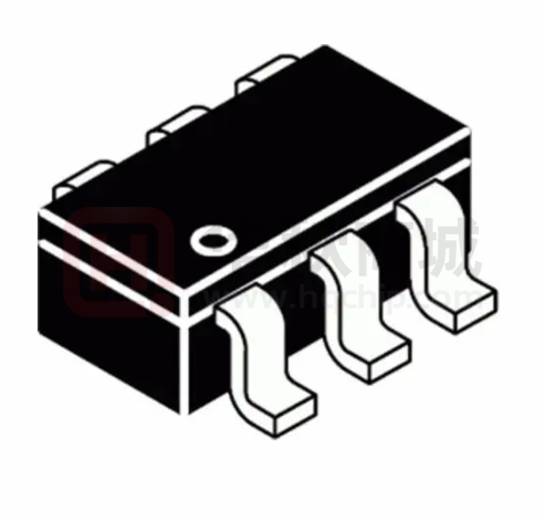
SOT-23-6 Package
Applications
LED Driver
IP Camera
LED Flashlights
Pin Assignments
Ordering Information
S6 Package (SOT-23-6)
FR9703 □
Package Type
S6: SOT-23-6 Package
ISEN VIN EN/D
6
5
4
(Marking)
1
2
3
LX GND NC
Figure 1. Pin Assignments of FR9703
FR9703-Preliminary 0.1-NOV-2019
SOT-23-6 Marking
Part Number
Product Code
FR9703S6
FU2
1
�FR9703
Typical Application Circuit
R SEN
VIN
C1
10μF
PWM or Analog
Signal
4
LED
6
ISEN
5
VIN
EN/D
D1
C2
1μF
FR9703
L1
6.8μH
LX 1
3 NC
LED
GND
2
Figure 2. Buck Application Circuit
L1
6.8μH
D1
VIN
1
LX
C1
10μF
PWM or Analog
Signal
4
VIN
EN/D
FR9703
ISEN
5
C3
1μF
R SEN
C2
1μF
RSEN
C2
1μF
6
LED
3 NC
GND
2
LED
Figure 3. Boost Application Circuit
VI N
L1
6.8μH
D1
1
LX
C1
10 μF
PWM or Analog
Signal
4
VIN
EN/D
5
C3
1μF
FR9703
ISEN
3 NC
GND
2
6
LED
LED
Figure 4. Buck-Boost Application Circuit
Note 1: LED dimming control can be done from either analog or PWM signal at the EN/D pin.
FR9703-Preliminary 0.1-NOV-2019
2
�FR9703
Functional Pin Description
Pin Name
Pin No.
Pin Function
LX
1
Power switching node. Connect an external inductor to this switching node.
GND
2
Ground pin.
NC
3
No connection. Keeps this pin floating.
EN/D
4
Enable control input and dimming control input . Logic high enables operation. This pin can select Analog
or PWM dimming controls the brightness of LEDs .
VIN
5
Power supply input pin. Placed input capacitors as close as possible from VIN to GND to avoid noise
influence.
ISEN
6
Current sense input pin. Connect an external resistor from VIN to ISEN to set the LED Current.
Block Diagram
VIN
UVLO
&
POR
EN/D
1M
Internal
Regulator
VCC
Input OVP
OTP
Oscillator
Analog & PWM
Dimming Control
LX
S
ISEN
ISEN
VIN
Current
Comp
R
Control
Logic
OTP
Driver
Logic
Internal
MOSFET
UVLO
Current
Limit
GND
Figure 5. Block Diagram of FR9703
FR9703-Preliminary 0.1-NOV-2019
3
�FR9703
Absolute Maximum Ratings
(Note 2)
● Supply Voltage VIN ------------------------------------------------------------------------------------------------ 0.3V to +28V
● Enable Voltage VEN/D ---------------------------------------------------------------------------------------------0.3V to +28V
● ISEN VISEN -----------------------------------------------------------------------------------------------------------0.3V to +28V
● LX Voltage VLX ------------------------------------------------------------------------------------------------ -0.3V to VIN +0.3V
● All Other Pins Voltage -------------------------------------------------------------------------------------- -0.3V to +6V
● Maximum Junction Temperature (TJ) --------------------------------------------------------------------- +150°C
● Storage Temperature (TS) -------------------------------------------------------------------------------------- 65°C to +150°C
● Lead Temperature (Soldering, 10sec.) ------------------------------------------------------------------- +260°C
● Package Thermal Resistance, (θJA)
(Note 3)
SOT-23-6 ------------------------------------------------------------------------------------------ 250°C/W
● Package Thermal Resistance, (θJC )
SOT-23-6 ------------------------------------------------------------------------------------------ 110°C/W
Note 2: Stresses beyond this listed under “Absolute Maximum Ratings" may cause permanent damage to the device.
Note 3: θJA is measured at 25°C ambient with the component mounted on a high effective thermal conductivity 4-layer
board of JEDEC-51-7. The thermal resistance greatly varies with layout, copper thickness, number of layers and PCB size.
Recommended Operating Conditions
● Supply Voltage VIN ------------------------------------------------------------------------------------------ +2.8V to +24V
● Operation Temperature Range --------------------------------------------------------------------------- -40°C to +85°C
FR9703-Preliminary 0.1-NOV-2019
4
�FR9703
Electrical Characteristics
(VIN=12V, TA=25°C, unless otherwise specified .)
Symbol
Conditions
VIN Quiescent Current
IDDQ
VEN/D=1.2V, VISEN=0.3V
VIN Shutdown Supply Current
ISD
VEN/D=0V
Parameter
Reference Voltage
96
VREF
MOSFET RDS(ON)
RDS(ON)
MOSFET Leakage Current
ILX(leak)
Min
Typ
Max
Unit
100
200
pA
10
pA
104
mV
100
mQ
200
10
VEN/D=1.2V, VLX=24V
1.7
pA
A
LX Current Limit
ILIMIT
Oscillation Frequency
FOSC
1.2
MHz
Maximum Duty Cycle
DMAX
100
%
TMIN
100
ns
2.5
V
200
mV
Minimum On Time
(Note 4)
Input Supply Voltage UVLO Threshold
VUVLO(Vth)
Input Supply Voltage UVLO Threshold
Hysteresis
VUVLO(HYS)
VIN Rising
EN/D High-Level Input Voltage
VEN/D
VEN/D Rising
EN/D Low-Level Input Voltage
VEN/D
VEN/D Falling
Analog Dimming Range
VEN/D
0.65
V
0.65
0.3
V
1.2
V
Analog Dimming Scale
VEN/D = 0.65V
5
%
Analog Dimming Scale
VEN/D = 1.2V
100
%
VIN_OVP
26.7
V
TSD
150
°C
THYS
20
°C
Input Over Voltage Protection
Thermal Shutdown Temperature
Thermal Shutdown Hysteresis
(Note 4)
(Note 4)
Note 4: Not production tested.
FR9703-Preliminary 0.1-NOV-2019
5
�FR9703
Typical Performance Curves
VIN=12V, IOUT=1.0A, 1S2P LED
SW
VIN=15V, IOUT=1.0A, 2S2P LED
SW
5V/div.
VLED
1V/div.
IL
500mA/div.
5V/div.
VLED
IL
2V/div.
500mA/div.
1μs/div.
1μs /div.
Figure 6. Switching Waveform
Figure 7. Switching Waveform
VIN=24V, IOUT=1.0A, 5S2P LED
SW
VLED
IL
VIN=12V, IOUT=1.0A, 1S2P LED
10V/div.
VIN
5V/div.
SW
5V/div.
VLED
2V/div.
5V/div.
1A/div.
ILED
500mA/div.
1μs /div.
10ms /div.
Figure 8. Switching Waveform
Figure 9. Power On through VIN Waveform
VIN=12V, IOUT=1.0A, 1S2P LED
VIN=12V, IOUT=1.0A, 1S2P LED
VIN
5V/div.
SW
5V/div.
VLED
2V/div.
ILED
500mA/div.
VEN
1V/div.
SW
5V/div.
VLED
2V/div.
ILED
500mA/div.
20ms /div.
2ms/div.
Figure 10. Power Off through VIN Waveform
Figure 11. Power On through EN Waveform
FR9703-Preliminary 0.1-NOV-2019
6
�FR9703
Typical Performance Curves ( Continued)
VIN=12V, IOUT=1.0A, 1S2P LED
VEN
1V/div.
SW
5V/div.
VLED
ILED
2V/div.
500mA/div.
100ms /div.
Figure 12. Power Off through VEN Waveform
Figure 13. Efficiency vs. Input Voltage
Figure 14. Frequency vs. Input Voltage
(IOUT=0.5A)
Figure 15. Frequency vs. Temperature
(IOUT=0.5A, 2S2P LED)
Figure 16. Quiescent Current vs. Temperature
Figure 17. Reference Voltage vs. Temperature
FR9703-Preliminary 0.1-NOV-2019
(IOUT=0 .5A, 2S2P LED)
7
�FR9703
Typical Performance Curves ( Continued)
Figure 18. EN/D Voltage vs. Temperature
(IOUT=0 .5A, 2S2P LED)
Figure 19. Analog Dimming :ILED vs. EN Voltage
(VIN=12V)
Figure 20. Digital Dimming :ILED vs. PWM Duty
(VIN=12V, 3S2P LED)
FR9703-Preliminary 0.1-NOV-2019
8
�FR9703
Function Description
The FR9703 is constant frequency and current
mode control LED driver IC. It has integrated 200mQ
power MOSFET, and provides 1.5A output current.
It regulates input voltage from 2.8V to 24V.
Over Current Protection
The stability of the ISEN circuit is controlled through
internal compensation circuits. This internal
compensation function is optimized for most
applications and this function can reduce external R,
C components.
The FR9703 over current protection function is
implemented using cycle-by-cycle current limit
architecture. The inductor current is monitored by
measuring the MOSFET series sense resistor
voltage. When the load current increases, the
inductor current also increases. When the inductor
current reaches the current limit threshold, the
output voltage starts to drop. When the over current
condition is removed, the output voltage returns to
the regulated value.
Enable and Dimming Control
Over Temperature Protection
The FR9703 EN/D pin provides digital control to
enable and disenable the converter. When the
voltage of EN/D exceeds the threshold voltage, the
FR9703 will operate enables. If the EN/D pin voltage
is below than the shutdown threshold voltage, the
FR9 70 3 will turn into the shutdown mode and the
shutdown current is around 10pA (typ). This pin
includes a 0.65V to 1.2V analog dimming input
which can be used for linear dimming of the LED
current. It includes a PWM dimming input that can
accept an external control signal with a duty ratio of
5% to 100% and PWM dimming is from 100Hz to
1kHz.
The FR9703 incorporates an over temperature
protection circuit to protect itself from overheating.
When the junction temperature exceeds the thermal
shutdown threshold temperature, the regulator will
be shutdown. And the hysteretic of the over
temperature protection is 20°C (typ).
Internal Compensation Function
Input Under Voltage Lockout
When the FR9703 is power on, the internal circuits
are held inactive until VIN voltage exceeds the input
UVLO threshold voltage. And the regulator will be
disabled when VIN is below the input UVLO
threshold voltage. The hysteretic of the UVLO
comparator is 200mV (typ).
Input Over Voltage Protection
When the VIN pin voltage exceeds 26.7V, the output
over voltage protection function will be triggered and
turn off the MOSFET.
FR9703-Preliminary 0.1-NOV-2019
9
�FR9703
Application Information
Setting LED Current
The LED current ILED is set using a resistor from the
VIN to ISEN. The ISEN pin regulated voltage is
100mV. Thus the LED current is:
The following figures show the form of the ripple
contributions.
VRIPPLE( ESR) ( t)
RSEN=
Input Capacitor Selection
The use of the input capacitor is filtering the input
voltage ripple and the MOSFETS switching spike
voltage. Because the input current to the step-down
converter is discontinuous, the input capacitor is
required to supply the current to the converter to
keep the DC input voltage. The capacitor voltage
rating should be 1.25 to 1.5 times greater than the
maximum input voltage. The input capacitor ripple
current RMS value is calculated as:
ICIN(RMS)=IOUT 根 D根 1-D
D=
Where D is the duty cycle of the power MOSFET.
A low ESR capacitor is required to keep the noise
minimum . To select the X7R (-55°C to 125°C) or X5R
(-55°C to 85°C) ceramic capacitors are better, but
tantalum or low ESR electrolytic capacitors may also
suffice. When using tantalum or electrolytic
capacitors, a 0.1pF ceramic capacitor should be
placed as close to the IC as possible.
+
VRIPPLE( ESL) ( t)
(t)
+
VRIPPLE( C) ( t)
(t)
+
VNOISE (t)
(t)
=
VRIPPLE( t)
(t)
Output Capacitor Selection
The output capacitor is used to keep the DC output
voltage and supply the load transient current. When
operating in constant current mode, the output ripple
is determined by four components:
VRIPPLE t = VRIPPLE C
t + VRIPPLE ESR
t
VRIPPLE( ESR)=
VRIPPLE( ESL) =
1-
ESR
VIN
+VRIPPLE( ESL) t +VNOISE t
VRIPPLE(C)=
FR9703-Preliminary 0.1-NOV-2019
1-
10
�FR9703
Application Information ( Continued)
Where FOSC is the switching frequency, L is the
inductance value, VIN is the input voltage, ESR is the
equivalent series resistance value of the output
capacitor, ESL is the equivalent series inductance
value of the output capacitor and the COUT is the
output capacitor.
Low ESR capacitors are preferred to use.
Ceramic, tantalum or low ESR electrolytic capacitors
can be used depending on the output ripple
requirement. When using the ceramic capacitors,
the ESL component is usually negligible.
It is important to use the proper method to eliminate
high frequency noise when measuring the output
ripple. The figure shows how to locate the probe
across the capacitor when measuring output ripple.
Removing the scope probe plastic jacket in order to
expose the ground at the tip of the probe. It gives a
very short connection from the probe ground to the
capacitor and eliminating noise.
Probe Ground
That will lower ripple current and result in lower
output ripple voltage. The Δ L is inductor
peak-to-peak ripple current:
T
A good compromise value between size and
efficiency is to set the peak- to- peak inductor ripple
current Δ L equal to 30% of the maximum load
current. But setting the peak-to-peak inductor ripple
current Δ L between 20%~50% of the maximum load
current is also acceptable. Then the inductance can
be calculated with the following equation:
.
-
T(MA
T
T
F
To guarantee sufficient output current, peak inductor
current must be lower than the FR9703 high-side
MOSFET current limit. The peak inductor current is
as below:
P A
T(MA
I PEAK
VOUT
GND
Ceramic Capacitor
T
-
F
∆IL
IOUT( MAX)
Time
Inductor Selection
The output inductor is used for storing energy and
filtering output ripple current. But the trade-off
condition often happens between maximum energy
storage and the physical size of the inductor. The
first consideration for selecting the output inductor is
to make sure that the inductance is large enough to
keep the converter in the continuous current mode.
FR9703-Preliminary 0.1-NOV-2019
11
�FR9703
Outline Information
SOT-23-6 Package (Unit: mm)
SYMBOLS
UNIT
DIMENSION IN MILLIMETER
MIN
MAX
A
0.90
1.45
A1
0.00
0.15
A2
0.90
1.30
B
0.30
0.50
D
2.80
3.00
E
2.60
3.00
E1
1.50
1.70
e
e1
0.90
1.00
1.80
2.00
L
0.30
0.60
Note 5: Followed From JEDEC MO- 178-C .
Note 6 : Body dimensions do not include mold
flash or protrusion. Mold flash and protrusion
shall not exceed 0. 3 mm.
Carrier dimensions
Life Support Policy
Fitipower’ s products are not authorized for use as critical components in life support devices or other medical systems .
FR9703-Preliminary 0.1-NOV-2019
12
�


 工商网监
湘ICP备2023018690号
工商网监
湘ICP备2023018690号
