Part No:
FXC.40 Series
Description:
Circular Form Factor Flexible Near Field Communications Antenna
Features:
13.56 MHz Antenna
Flexible Low Profile Embedded
Typical interrogation distance: 40 mm
Dimensions:
•
Diameter: 40 mm
•
Thickness: 0.14 mm - FXC.40.A - NFC without ferrite
•
Thickness: 0.27 mm - FXC.40.A.dg - NFC with ferrite
•
Thickness: 0.27 mm - FXC.40.52.0075X.A.dg - NFC with ferrite and 75mm
twisted cable.
Peel and stick 3M adhesive
RoHS & Reach Compliant
SPE-22-8-130-A
�1.
Introduction
3
2.
Specifications
4
3.
Antenna Application
5
4.
Mechanical Drawing
10
5.
Packaging
13
Changelog
14
Taoglas makes no warranties based on the accuracy or completeness of the contents of this document and reserves the right to
make changes to specifications and product descriptions at any time without notice. Taoglas reserves all rights to this document and
the information contained herein. Reproduction, use or disclosure to third parties without express permission is strictly prohibited.
SPE-22-8-130-A
www.taoglas.com
2
�1.
Introduction
1.
Introduction
1.
Introduction
1.
Introduction
1.
Introduction
The Taoglas FXR and FXC series of high-performance NFC (Near Field Communications) antennas are ideal
for IoT and mobile devices and for applications such as contactless payment systems, access control or RFID
systems.
1.
1.
1.
Introduction
The compact, flexible NFC antennas are supplied with adhesive backing for quick and easy installation and
can be mounted inside a plastic device enclosure or on an internal battery. For any NFC antennas that are
attached to the battery, we offer variants with ferrite flux directors to provide isolation from the battery or
other electronic components within the device. Using the antenna on a conductive surface without a ferrite
layer could result in losses on the antenna communication performance.
Introduction
Taking into consideration the many environments that the antenna could be used, Taoglas offers three
versions of each of the FXR and FXC series models. A standard model without ferrite and adhesive backing, a
model with a ferrite layer and adhesive backing and a third model with ferrite and a 75mm Twisted Pair
28AWG cable with ACH(F) connectors.
Introduction
Typical Applications Include:
-
Mobile Devices
Wearable Smart Devices
Payment Terminals
Device tracking and ID systems
Access control
For further optimization to customer-specific device environments and for support to integrate and test this
antennas performance in your device, contact your regional Taoglas Customer Services Team.
SPE-22-8-130-A
www.taoglas.com
3
�2.
Specifications
3.
Antenna Characteristics2.
Part Number
3.
4.
4.
13.56 MHz
13.56 MHz
0.99 µH
1.07 µH
Rs
0.86 ohm
1.24 ohm
1.52 ohm
Q Factor
70.3
68
60
Antenna Radiation Patterns3.Antenna
Specifications
Self-Resonance Frequency
154.8 MHz
119.7 MHz
78.4 MHz
Rp
12.6 kohm
5.22 kohm
4.05 kohm
Antenna Characteristics2.
Specifications
Mechanical
Diameter: 40 mm
Diameter: 40 mm
Diameter: 40 mm
0.27 mm
0.27 mm
Thickness
0.14 mm
Antenna
Characteristics
RoHS Compliant
Yes
Yes
Yes
Adhesive
3M467 or 3M9460
3M467 or 3M9460
3M467 or 3M9460
Antenna Radiation Patterns3.Antenna
Weight
Operation Temperature
1g
1g
1g
-40°C to 85°C
-40°C to 85°C
-40°C to 85°C
-40°C to 85°C
Non-condensing 65°C 95%
RH
Non-condensing 65°C 95% RH
Environmental
-40°C to 85°C
Storage Temperature
-40°C to 85°C
Antenna
Radiation Patterns
Humidity
4.
FXC.40.52.0075X.A.dg
0.71 µH
Characteristics
4.
FXC.40.A.dg
La
Antenna Dimensions
3.
FXC.40.A
FrequencyCharacteristics
13.56 MHz
Antenna
Characteristics2.
3.
Specifications
Electrical
Non-condensing 65°C
95% RH
* Contact pads are gold plated copper. Base material is polyimide which can take heat from soldering for brief periods suitable for
attaching wires. Additional wire length will affect read range and result in different performance than that detailed in this document.
Antenna Radiation Patterns3.Antenna
Characteristics
4.
Antenna Radiation Patterns3.Antenna
SPE-22-8-130-A
Characteristics2.
Specifications
www.taoglas.com
4
�3.
4.
Antenna Application
3.1
Test Setup
Antenna Radiation Patterns3.Antenna
Characteristics
A test fixture is used to measure the maximum interrogation distance. The
FXC.40.A antenna is
connected to NFC evaluation boards and then placed under the PC material blocks to communicate with
the standard card above them.
4.
4.
Antenna Radiation Patterns
The Demo
boards
Antenna Radiation Patterns3.Antenna
The standard
card
Characteristics
PC blocks
4.
Antenna Radiation Patterns3.Antenna
FXC.40.A
Characteristics
The POS
machines
4.
The Demo
boards
Antenna Radiation Patterns
PC blocks
4.
Antenna Radiation Patterns
FXC.40.A
4.
Antenna Radiation Patterns
When the number of the PC material blocks are carefully adjusted until the reader can no longer read
the sample, that’s mean in this point the FXC.40.A cannot establish communication with the standard
card or the POS machine, the thickness of the PC material block is the maximum interrogation distance
4.
Antenna Radiation Patterns3.Antenna
of them.
Characteristics
4.
Antenna Radiation Patterns3.Antenna
SPE-22-8-130-A
www.taoglas.com
5
�3.2
RFID Tags and POS Used for Test
A total of 5 NFC forum tags were used to measure the interrogation distances. The next picture shows
type 1, type 2, type 3, type 4 and type 5 tags, respectively.
Type 1 is based on ISO/IEC 14443A standard and has 96 bytes of memory.
Type 2 is based on ISO/IEC 14443A standard and has 144 bytes of memory.
Type 3 is based on ISO-18092, JIS-X-6319-4 Sony Felica standard and has 9k bytes of memory.
Type 4 is based on ISO / IEC 14443A 1-4 compliant and has 4K of memory
Type 5 is based on ISO-15693 specification, the communication with this NFC Forum Tag type is based on
NFC-V Technology.
SPE-22-8-130-A
www.taoglas.com
6
�3.3
The POS machine used for test
The next picture shows the POS machine using to measure the Card emulation performance of the
FXC.40 Series NFC antennas.
ACR122 is a PC-linked contactless smart card reader/writer developed on the 13.56MHz Contactless
(RFID) Technology and followed the ISO/IEC18092 Standard for Near Field Communication (NFC),
supporting not only MIFACE® ISO 14443 A and B cards but also NFC and FELICA contactless
technologies.
The ACR122 is a USB Plug and Play device with CCID compliance. By making use of up to 424 Kbps for
NFC Tag access and full USB speed of up to 12 Mbps, the ACR122 can read and write faster and more
efficiently. The proximity operating distance of ACR122 is up to 5 cm, depending on the type of
contactless tag in use. Operating distance can be extended on request by adding an RF boaster, so the
ACR122 is suitable for logistics and supply chain management.
T6-BU-00-00 is a 13.56MHz high frequency readable and writable device, a USB drive-free RFID reader
card which supports ISO14443 standard protocol Class A card reading and writing read and write. Also,
T6-BU-00-00 is a module that can be set to read and write a chip card that supports the ISO15693
standard protocol.
SPE-22-8-130-A
www.taoglas.com
7
�3.3
Matching
The interrogation distances presented here were taken with the antenna connected directly to the
evaluation boards with the optimzed matching circuit. For the NXP PN553 chipset, it is sugguesd using
20ohm impendence of the NFC antenna. Just like below:
As with any matching network the exact circuit and values for an optimal network depend on the
combination of antenna, NFC circuit, any intervening transmission line and the environment presented
to the antenna. These factors are specific to the particular end product.
As a starting point, to achieve the read range results presented here, use the matching network detailed
in the schematic of the evaluation board for your particular NFC chip and keep the antenna free of any
obstruction. Once you can demonstrate successful reads you can then optimize performance as desired.
SPE-22-8-130-A
www.taoglas.com
8
�3.4
Read/Write & Card emulation mode
The NFC forum card type 1~5 were used to measure the interrogation distances in Read/write mode. The POS
machine ACR122, T6-14443 T6-15693 were used to measure the interrogation distances in Card emulation mode.
The results are in the next tables:
Device
Interrogation Distance(mm)
FXC.40.A
FXC.40.A.dg
FXC.40.52.0075X.A.dg
Topaz512 (Type 1)
71
42
39
NTAG203 (Type 2)
72
42
39
Sony Felica (Type 3)
52
29
25
Mifare DESFire (Type 4)
46
23
20
ISO 15693 (Type 5)
120
77
74
ACR122
115
66
59
T6-14443
90
49
45
T6-15693
122
67
60
SPE-22-8-130-A
www.taoglas.com
9
�4.
Mechanical Drawing (Units: mm)
4.1
FXC.40.A
6.
Packaging5.
Mechanical Drawing
6.
Packaging
7.
Application Note6. Packaging5.
Mechanical
Drawing
6.
Packaging5.
Mechanical Drawing
6.
Packaging
7.
Application Note6. Packaging
7.
Application Note
7.
Application Note6. Packaging
7.
Application Note6. Packaging5.
Mechanical
Drawing
6.
Packaging5.
SPE-22-8-130-A
Mechanical Drawing
www.taoglas.com
10
�4.2
FXC.40.A.dg
SPE-22-8-130-A
www.taoglas.com
11
�4.3
FXC.40.52.0075X.A.dg
SPE-22-8-130-A
www.taoglas.com
12
�5.
Packaging
6.
Packaging5.
6.
Packaging
FXC.40
Series
1 pcs / Small PE Bag
7.
Mechanical Drawing
Application Note6. Packaging5.
Mechanical
Drawing
6.
6.
Packaging5.
Mechanical Drawing
100pcs/ Grid of Honeycomb Board
Packaging
7.
Application Note6. Packaging
7.
Application Note
7.
7.
Honeycomb
Board 1Note6.
set
Application
Packaging
Carton(mm): 230(L)x175(W)x160(H)
Carton board 2 pcs
Carton Label
Application Note6. Packaging5.
Mechanical
Drawing
6.
Packaging5.
SPE-22-8-130-A
Mechanical Drawing
www.taoglas.com
13
�Changelog for the datasheet
SPE-22-8-130 – FXC.40 Series
Revision: A (Original First Release)
Date:
Notes:
2022-09-01
Author:
Cesar Sousa
Previous Revisions
SPE-22-8-130-A
www.taoglas.com
14
�www.taoglas.com
SPE-22-8-130-A
© Taoglas 15
www.taoglas.com
�
很抱歉,暂时无法提供与“FXC.40.A.DG”相匹配的价格&库存,您可以联系我们找货
免费人工找货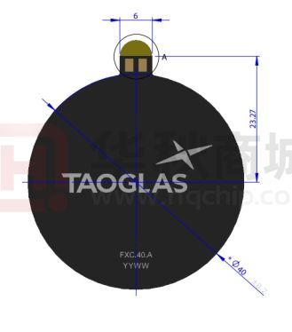


 工商网监
湘ICP备2023018690号
工商网监
湘ICP备2023018690号
