Type
NUMBER
PRODUCT SPECIFICATION
TITLE
GS-12-233
PAGE
REV.
TM
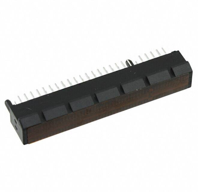
PCI EXPRESS CONNECTOR
AUTHORIZED BY
Richard Chiu
TABLE
OF
INTRODUCTION
SECTION 2
GENERAL REQUIREMENTS
07/04/08
MECHANICAL
3.1
3.2
3.3
3.4
3.5
SECTION 4
EXAMINATION OF PRODUCT
INSERTION/WITHDRAWAL FORCES – ADD IN CARD
CONTACT RETENTION
BOARD INSERTION/RETENTION FORCE
SOLDERABILITY
ELECTRICAL
4.1
4.2
4.3
4.4
4.5
4.6
4.7
SECTION 5
DATE
CONTENTS
SECTION 1
SECTION 3
H
1 of 11
LOW LEVEL CONTACT RESISTANCE
INSULATION RESISTANCE
DIELECTRIC WITHSTANDING
CONTACT CURRENT RATING
INSERTION LOSS
RETURN LOSS
CROSSTALK
ENVIRONMENTAL
5.1 THERMAL SHOCK
5.2 CYCLIC TEMPERATURE AND HUMIDITY
5.3 TEMPERATURE LIFE (PRE-CONDITIONING)
5.4 TEMPERATURE LIFE
5.5 VIBRATION
5.6 DURABILITY (PRE-CONDITIONING)
5.7 DURABILITY
5.8 MIXED FLOWING GAS
5.9 RESEATING
5.10 RESISTANCE TO SOLDER HEAT
SECTION 6
TEST MATRIX
This document is the property of and embodies CONFIDENTIAL and PROPRIETARY information of FCI. No part of the information shown on the document may be used in any way or
disclosed to others without the written consent of FCI. Copyright FCI.
Form E-3005
Rev E
GS-01-001
PDM: Rev:H
STATUS:Released
Printed: Nov 27, 2010.
�Type
NUMBER
PRODUCT SPECIFICATION
TITLE
GS-12-233
PAGE
TM
PCI EXPRESS CONNECTOR
REV.
H
2 of 11
AUTHORIZED BY
Richard Chiu
DATE
07/04/08
1.0 INTRODUCTION
1.1 SCOPE
This document describes
the functional and test requirements
for the PCI ExpressTM card-edge connector. The connector is
designed to meet the requirements of the PCI Express Card
Electromechanical Specification and certain customer
specifications not covered by the PCI-SIG document.
1.2 APPLICABLE DOCUMENTS
1.2.1
1.2.2
1.2.3
1.2.4
1.2.5
1.2.6
Solderability : BUS-19-002/A
PCI Express Card Electromechanical Specification
EIA –90, EIA-36409,17,20,21,28,31,32,65,70,101,108,638
PCI Express Connector High Speed Electrical Test
Procedure.
FCI drawing, PCI Express connector, inspection &
customer copy.
FCI drawing, solder washer, 78523 : inspection copy.
1.3 DRAWING PRECEDENCE
In the event of conflict between this document and product
prints, the product prints shall take precedence.
2.0 GENERAL REQUIREMENTS
2.1
2.2
2.3
2.4
2.5
The connector has the following characteristics:
1.00m(0.040”) pitch, X1, X4, X8, X16 sizes, through hole
or straddle mount configuration, rectangular outline,
plastic peg or two forklock holdowns requiring TH holes
on PCB.
Visual examination, unless otherwise specified, shall be
made at 7X.
Silicone compounds (mold releases, lubricants, etc.) May
not be used in the manufacturing processes.
Flammability to be rated UL 94V-0.
Unless otherwise specified, tests that require the use of
a pc edge card shall use the following
2.5.1Card material: FR-4 glass epoxy.
2.5.2Thickness: 1.57 +/- 0.13 (0.062 +/- 0.005 inch)
2.5.3Trace material: 0.035 (0.0014 inches), copper.
2.5.4Trace plating: 0.76 micrometers (30 microinches)
minimum gold over 1.27 micrometers (50 microinches)
minimum unbrushed nickel
This document is the property of and embodies CONFIDENTIAL and PROPRIETARY information of FCI. No part of the information shown on the document may be used in any way or
disclosed to others without the written consent of FCI. Copyright FCI.
Form E-3005
Rev E
GS-01-001
PDM: Rev:H
STATUS:Released
Printed: Nov 27, 2010.
�Type
NUMBER
PRODUCT SPECIFICATION
TITLE
GS-12-233
PAGE
TM
PCI EXPRESS CONNECTOR
REV.
H
3 of 11
AUTHORIZED BY
Richard Chiu
DATE
07/04/08
2.5.5Pad and trace design: pad and trace design shall follow
PCI Express standard as depicted in customer drawing.
2.6 SOLDERTAIL TERMINATION
Tests requiring termination of the soldertails to a PC
board shall be prepared as follows:
2.6.1A 2.4mm +/- 0.13 (0.094 +/- 0.005) thick FR-4 glass
epoxy board having no internal ground planes with
plated thru holes in the pattern specified in AFCI
customer drawing, shall be used.
2.6.2 Solder washers, AFCI part number 78523-001, shall be
applied to the tails, and the connector vapor phase
reflowed at 215°C (419°F) for a time not to exceed 2
minutes.
3.0 MECHANICAL REQUIREMENTS
3.1
EXAMINATION OF PRODUCT
Samples must comply to applicable FCI product prints.
3.2 INSERTION / WITHDRAWAL FORCE- ADD IN CARD
PER EIA-364-13
Mating cycle is with maximum/minimum thickness gage at a rate
of 25.4 mm/minute.
3.2.1 Maximum insertion force is 1.15 N max. per contact pair
when measured with a 1.70 +0.00/-0.01(0.067 +0.000/
-0.004 inches) thick hardened steel card made to the
dimensions shown for the PCI Express expansion board
in the FCI customer drawing. The card has a R0.05 min.,
R0.10 max.(sharpedge)and the surface roughness in
connector area to be 0.10 micrometers (4 microinches)
maximum.
3.2.2 Withdrawal force is 0.15N minimum per contact pair when
measured with a 1.44 +0.01/-0.00 (0.067 +0.004/-0.000
inches) thick hardened steel card made to the
dimensions shown for the PCI Express expansion board
in the FCI customer drawing. The card has a R0.05
min., R0.10 max (sharp edge) and the surface
roughness in the connector area to be 0.10 micrometers
(4 microinches) maximum.
3.3
CONTACT RETENTION
This document is the property of and embodies CONFIDENTIAL and PROPRIETARY information of FCI. No part of the information shown on the document may be used in any way or
disclosed to others without the written consent of FCI. Copyright FCI.
Form E-3005
Rev E
GS-01-001
PDM: Rev:H
STATUS:Released
Printed: Nov 27, 2010.
�Type
NUMBER
PRODUCT SPECIFICATION
TITLE
GS-12-233
PAGE
TM
PCI EXPRESS CONNECTOR
REV.
H
4 of 11
AUTHORIZED BY
Richard Chiu
DATE
07/04/08
Minimum retention force of terminals in the connector
housing to be 5N each. Pull rate to be 1.27 mm/min.
3.4 BOARD RETENTION / INSERTION FORCES
3.4.1 Board retention / insertion forces should be checked on
an 1.57 +/- 0.13 (0.062 +/- 0.005 inch) thick segment
of FR-4 glass / epoxy circuit board segment with a
hole of diameter as described below drilled through.
Connectors should have all contacts present. Forces
apply to connectors with plastic pegs and metal board
locks.
3.4.2 Maximum insertion force(including all types post or
straddle mount solder tails) to seat connector in
PCB(including straddle mount or through PCB)are:
36 pos
2.14 kg max.
64 pos
3.91 kg max.
98 pos
7.45 kg max.
164 pos
7.45 kg max.
3.5 SOLDERABILITY
Per J-STD-002
a. steam age for 1 hour
b. contact areas evaluated shall meet 95% minimum coverage.
4.0 ELECTRICAL REQUIREMENTS
Unless otherwise specified, all measurements should be
performed in the following ambients:
relative humidity:
temperature:
barometric pressure:
50% or less
25°C +/- 5°c
711 to 812 mm mercury (at sea level)
4.1 LOW LEVEL CONTACT RESISTANCE
EIA-364-23
This document is the property of and embodies CONFIDENTIAL and PROPRIETARY information of FCI. No part of the information shown on the document may be used in any way or
disclosed to others without the written consent of FCI. Copyright FCI.
Form E-3005
Rev E
GS-01-001
PDM: Rev:H
STATUS:Released
Printed: Nov 27, 2010.
�Type
NUMBER
PRODUCT SPECIFICATION
TITLE
GS-12-233
PAGE
REV.
TM
PCI EXPRESS CONNECTOR
H
5 of 11
AUTHORIZED BY
Richard Chiu
DATE
07/04/08
4.1.1Solder connector to pc board per section 2.6 and insert card
per section 2.5
4.1.2Resistance measurements should be made from the underside of
the pc board to the PTH in the add-in card above the contact
pad. The test current shall be 100 milliampere d.c. max.
with a maximum open circuit voltage of 20 millivolts D.C.
See figure 1.0 for attachment of current and voltage leads.
4.1.3Requirement is 30 milliohms maximum initial, with change of 10
milliohms maximum after exposure testing.
CONTACT RESISTANCE TEST SET UP
THROUGH HOLE
FIGURE 1
This document is the property of and embodies CONFIDENTIAL and PROPRIETARY information of FCI. No part of the information shown on the document may be used in any way or
disclosed to others without the written consent of FCI. Copyright FCI.
Form E-3005
Rev E
GS-01-001
PDM: Rev:H
STATUS:Released
Printed: Nov 27, 2010.
�Type
NUMBER
PRODUCT SPECIFICATION
TITLE
GS-12-233
PAGE
REV.
TM
PCI EXPRESS CONNECTOR
H
6 of 11
AUTHORIZED BY
Richard Chiu
DATE
07/04/08
CONTACT RESISTANCE TEST SET UP
STRADDLE MOUNT
FIGURE 2
4.2 INSULATION RESISTANCE
Requirement is 1000 megohm minimum at 100 + / - 10% vdc when
tested to EIA-364-21 per spec. The connector shall not be mated
during insulation resistance measurement.
4.3 DIELECTRIC WITHSTANDING
Per EIA-364-20 method B per spec. Test potential to be 300 VAC RMS,
60 HZ, and applied for 1 minute. No breakdown should occur. Test
is performed with connector unmated.
4.4 CONTACT CURRENT RATING
1.1 amp per contact minimum per EIA-364—70, method 2 and PCI
Express Connector High Speed Electrical Test Procedure. The
temperature rise shall not exceed 30 degree C. Ambient condition
is still air at 25°C.
4.5 INSERTION LOSS
Per EIA-364-101 and PCI Express Connector High Speed Electrical
Test Procedure.
Requirements:
Less than or equal to 1dB up to 1.25 GHz
This document is the property of and embodies CONFIDENTIAL and PROPRIETARY information of FCI. No part of the information shown on the document may be used in any way or
disclosed to others without the written consent of FCI. Copyright FCI.
Form E-3005
Rev E
GS-01-001
PDM: Rev:H
STATUS:Released
Printed: Nov 27, 2010.
�Type
NUMBER
PRODUCT SPECIFICATION
TITLE
GS-12-233
PAGE
TM
PCI EXPRESS CONNECTOR
REV.
H
7 of 11
AUTHORIZED BY
Richard Chiu
DATE
07/04/08
Less than or equal to 1.6 x (F-1.25)+1) db between
1.25GHz and 3.75GHz.
Less than or equal to 5 dB at 3.75 GHz
4.6 RETURN LOSS
Per EIA-364-108 and
Test Procedure.
Requirements:
Less than
Less than
Less than
PCI Express Connector High Speed Electrical
or equal to -12dB up to 1.3 GHz
or equal to -7dB up to 2.0 GHz
or equal to -4dB up to 3.75 GHz
4.7 CROSSTALK: NEXT
Per EIA-90 and PCI Express Connector
Procedure.
Requirements:
Less than or equal to -32 dB max
Less than or equal to –(32 – 2.4
GHz and 3.75GHz.
Less than or equal to -26 dB max
High Speed Electrical Test
up to 1.25 GHz
x (F-1.25)) db between 1.25
up to 3.75 GHz
5.0 ENVIRONMENTAL REQUIREMENTS (Per EIA-364-1000.01)
5.1 THERMAL SHOCK
Per EIA-364-32, test condition I, 10 cycles
5.2 CYCLIC TEMPERATURE AND HUMIDITY
Per EIA-364-31, 24 cycles
5.3 TEMPERATURE LIFE (Pre-conditioning)
Per EIA-364-17, method A, 92 hours at 105°C
5.4 TEMPERATURE LIFE
Per EIA-364-17, method A, 168 hours at 105°C
5.5 VIBRATION
Per EIA-364-28, test condition VII, test condition letter D.
Requirements: no evidence of physical damage
5.6 DURABILITY (Pre-conditioning)
CYCLE RATE : 500 MATING / HOUR
Per EIA-364-09, 20 cycles
This document is the property of and embodies CONFIDENTIAL and PROPRIETARY information of FCI. No part of the information shown on the document may be used in any way or
disclosed to others without the written consent of FCI. Copyright FCI.
Form E-3005
Rev E
GS-01-001
PDM: Rev:H
STATUS:Released
Printed: Nov 27, 2010.
�Type
NUMBER
PRODUCT SPECIFICATION
TITLE
GS-12-233
PAGE
REV.
TM
PCI EXPRESS CONNECTOR
H
8 of 11
AUTHORIZED BY
Richard Chiu
DATE
07/04/08
5.7 DURABILITY
CYCLE RATE : 500 MATING / HOUR
Per EIA-364-09, 50 cycles
5.8 MIXED FLOWING GAS
Per EIA-364-65, class IIA, 10 days exposure. Expose connectors
unmated for 2/3 of the total duration. Mate each connector to the
same add-in card that it was mated to in temperature life
(preconditioning) and expose for the remainder of the test
duration.
5.9 RESEATING
Manually plug/unplug the card and connector, 3 cycles.
5.10RESISTANCE TO SOLDERING HEAT
Per EIA-364-56 procedure 3, test condition C.
260°±5°C 10±2 seconds
This document is the property of and embodies CONFIDENTIAL and PROPRIETARY information of FCI. No part of the information shown on the document may be used in any way or
disclosed to others without the written consent of FCI. Copyright FCI.
Form E-3005
Rev E
GS-01-001
PDM: Rev:H
STATUS:Released
Printed: Nov 27, 2010.
�Type
NUMBER
PRODUCT SPECIFICATION
GS-12-233
TITLE
PAGE
REV.
TM
PCI EXPRESS CONNECTOR
H
9 of 11
AUTHORIZED BY
DATE
Richard Chiu
07/04/08
6.0 Test Matrix for 1X,4X,8X,& 16X
TABLE 1 - QUALIFICATION TESTING MATRIX
TEST
Examination of Product
Insertion/Withdrawal
Force – Add In Card
Contact Retention
Board Retention
/Insertion Forces
Solderability
Low Level Contact
Resistance
Insulation Resistance
DWV
Contact Current Rating
Insertion Loss
Return Loss
Crosstalk
Thermal Shock
Cyclic Temp and
Humidity
Temperature Life (preconditioning)
Temperature Life
Vibration
Durability (preconditioning)
Durability
Mixed Flowing Gas
Reseating
Resistance to soldering
heat
PARA
3.1
TEST
GROUP
TEST
GROUP
TEST
GROUP
TEST
GROUP
1
2
3
4
1
1
1
1
5
TEST
SEQUENCE
1
3.2
3.3
3
5
3.4
3.5
2
4
4.1
4.2
4.3
4.4
4.5
4.6
4.7
5.1
2,5,7
5.6
5.7
5.8
5.9
2,5,7
TEST
GROUP
TEST
GROUP
TEST
GROUP
6
7
8
1
1
1
2,5,7,9
,11
TEST
GROUP
9
1
3,5
2,6
2
2
3
4
4
5.2
5.3
5.4
5.5
2,5,8,
10
7
8
6
4
4
4
6
3
3
3
3
4
6
9
6
10
5.10
(1)
Sample Quantity / Group
TEST
GROUP
16X-5
(1)
200-5
(1)
280-5
16X-5
16X10,8X-10,
4X-10,1X(3)
16X-5
10
200-10,
200-5
(2)
280-5 16X-10 280-10
(4)
4X-3
16X-10
(1)
200-10
(1)
(5)
280-10
16X-4
2
16X-3
Plasti
c peg
16X-3
board
lock
This document is the property of and embodies CONFIDENTIAL and PROPRIETARY information of FCI. No part of the information shown on the document may be used in any way or
disclosed to others without the written consent of FCI. Copyright FCI.
Form E-3005
Rev E
GS-01-001
PDM: Rev:H
STATUS:Released
Printed: Nov 27, 2010.
�Type
NUMBER
PRODUCT SPECIFICATION
TITLE
GS-12-233
PAGE
TM
PCI EXPRESS CONNECTOR
REV.
H
10 of 11
AUTHORIZED BY
Richard Chiu
DATE
07/04/08
Notes:
1.
2.
samples for test groups 1,2,3,6 & 8 have metal hold downs, phos bronze
contacts and 0.38 micrometers (15 u”) gold plate, and black housings.
samples for test group 4:
a. 5 each same as note 1
b.
5 each same as note except with 0.76 micrometers (30u”) gold plate.
3.
samples for test group 5:
a.
5 each same as
b.
5 each same as
4. samples for test group 7:
a.
5 each same as
b.
5 each same as
note 1
note except with plastic locating pegs.
note 1
note except with 0.76 micrometers (30U”) gold plate.
5. samples for test group 8:
a.
2 each same as note 1
b.
2 each same as note except with 0.76 micrometers (30U”) gold plate.
This document is the property of and embodies CONFIDENTIAL and PROPRIETARY information of FCI. No part of the information shown on the document may be used in any way or
disclosed to others without the written consent of FCI. Copyright FCI.
Form E-3005
Rev E
GS-01-001
PDM: Rev:H
STATUS:Released
Printed: Nov 27, 2010.
�Type
NUMBER
PRODUCT SPECIFICATION
TITLE
GS-12-233
PAGE
TM
PCI EXPRESS CONNECTOR
REV.
H
11 of 11
AUTHORIZED BY
Richard Chiu
DATE
07/04/08
REVISION RECORD
REV
A
PAGE
ALL
RELEASED
B
ALL
c
ALL
D
ALL
E
DESCRIPTION
ECR #
T03-0302
DATE
07/21/2003
Add 5.10 on Sheet 7
Add group 9 on sheet 8
Modify 5.8 on sheet 7
T03-0463
T03-0513
10/17/03
11/24/03
03/10/04
ALL
3.2 add PER EIA-364-13 & cycle T04-0114
rate
4.1 add PER EIA-364-23
5.6 & 5.7 add cycle rate
ADD STRADDLE MOUNT TYPE
T04-0341
08/04/04
F
ALL
ADD 3.4.3
T04-0414
11/23/04
G
ALL
06/20/06
H
4
MODIFY 3.4.2, REMOVE 3.4.3 AND T06-0120
CHANGE FORM
SOLDERABILITY-REFERENCE
T08-1128
DOCUMENT WAS REPLACED BY “JSTD-002”
07/04/08
This document is the property of and embodies CONFIDENTIAL and PROPRIETARY information of FCI. No part of the information shown on the document may be used in any way or
disclosed to others without the written consent of FCI. Copyright FCI.
Form E-3005
Rev E
GS-01-001
PDM: Rev:H
STATUS:Released
Printed: Nov 27, 2010.
�


 工商网监
湘ICP备2023018690号
工商网监
湘ICP备2023018690号
