1136 ITT - CCM Catalog 11/20/00 12:28 PM Page 45
CCM04 MKII
The CCM04 without card guidance is
used where space is at a premium and
the card guidance can be built around
the connector (rather than provided by
the connector itself).
The CCM04 low profile without card
guidance is dedicated to applications
where the overall height of the
connector is paramount. A range of low
profile CCM04 connectors are available
with 1.25 mm thick moldings.
The wide choice of contact
configurations and molding heights suit
a broad range of applications.
Construction
Contacts
Plating
Copper alloy
Contact area : Gold alloy inlay
Terminals : Tin lead (2µ min)
High temp. thermoplastic UL 94V-0 rated
Moldings
Mechanical data
Number of Contacts
Mechanical life
Durability of inlay
Contact force
Card detection switch
actuation force
Features
Vibration
50m/s2
• Available in a variety of molding heights
from 1.25 mm to 5 mm.
Shock
• The integrated card detection switch
(optional) is sealed against dust and grit.
• By using an inlay finish in the contact
area, the life of the precious metal is
extended by more than 10 times that
of standard gold plating.
• The height of the contact above the
insulator is 0.75 mm, so allowing a
wider tolerance for the card entry slot.
• The contact area is spooned to
reduce the risk of accidental (or
deliberate) damage, and to optimize
the electrical connection with the card.
• The tip of the contact is protected by
the molding so that it cannot catch on
the card as the card is being inserted.
• The contact design ensures a
consistent and reliable contact force
over the life of the connector.
• Robustly formed printed circuit tails
are well protected by the insulator
body: a coplanarity of ± 0.05 mm is
guaranteed.
Electrical data
Insulation resistance
Contact resistance max
Switching current
Dielectric strength
Card detection switch
Switch contact resistance
Dielectric switch contacts
Maximum switch power
Environmental data
Operating temperature
Soldering temperature
Damp heat
Salt mist
Card detection switch
6, 8 or 16
50,000 cycles min
5,000 cycles min (see note 1)
0.25 N min / 0.5 N max
0.8 N max for actuation (end travel switch
actuates when card is 0.9 mm from
card stop) 1.8 N max for complete
depression
Frequency 10 to 500 Hz. Acceleration
Duration 6 hours - amplitude 0.35 mm
Max electrical discontinuity 1µs
Peak value 500 m/s2 – Duration 11 ms
3 shocks in each direction of each axis
Max electrical discontinuity 1 µs
1,000 MΩ min
100 mΩ max
10 µA min / 1 A max
750 Vrms min
Normally open (closes on card insertion)
100mΩ max
250 Vrms min
0.2 VA
-40°C to +85°C
Temperature/time profile acc. to CECC00802
para. 6.1, Fig. 3 with peak temperature 250°C
IEC 512 test number 11c (10 days)
IEC 512 test number 11f (96 hours)
Sealed IP 54 For CCM04 1889 & 1905
Sealed against dust for other versions
Note 1: Inlay (precious metal) rating is based on a very abrasive card being used and is
intended to represent worst case.
• The moldings are made from high
temperature thermoplastic suited for
infrared and convection soldering
processes.
• With tape and reel packaging as
standard, the connectors are designed
to be automatically picked & placed.
Dimensions are shown in mm
Dimensions subject to change
www.ittcannon.com/ccm
43
�1136 ITT - CCM Catalog 11/20/00 12:29 PM Page 46
CCM04 MKII
Ordering code
Molding Height
1.25 mm
1.25 mm
2.00 mm
2.75 mm
2.75 mm
3.50 mm
4.25 mm
5.00 mm
SMT Tails
Standard
Straight
Standard
Straight
Standard
Standard
Standard
Standard
Without Switch
2 x 3 contacts
2 x 4 contacts
CCM04-1801
CCM04-1814
CCM04-1800*
CCM04-1813*
CCM04-5004**
CCM04-1415*
CCM04-1200
CCM04-1217*
CCM04-1201
CCM04-1218
CCM04-1202
CCM04-1219*
CCM04-1203*
CCM04-1220
CCM04-1221
With Switch
2 x 4 contacts
2 x 8 contacts
CCM04-1889
CCM04-1905
CCM04-1888*
CCM04-1316
CCM04-1317
CCM04-1318
CCM04-1319*
CCM04-1320
CCM04-1333*
CCM04-1334
*Note: On request
**Note: Replaced by CCM04-5102 (see page 53)
Packaging
Connectors without a switch are packaged in accordance with EIA 481-2 or IEC 286-3.
Connectors with a switch are packaged in accordance with EIA 481-3 or IEC 286-3
Standard packaging is in tape and reel. A modification code is added to the part number that indicates
reel packaging and the number of components per reel (which varies according to the molding height).
Example: A CCM04 with 8 contacts plus switch and a molding height of 3.50 mm has a part number
CCM04-1318-R751.
Molding Height
SMT Tails
1.25 mm
1.25 mm
2.00 mm
2.75 mm
2.75 mm
3.50 mm
4.25 mm
5.00 mm
Standard
Straight
Standard
Straight
Standard
Standard
Standard
Standard
Without Switch
2x3
2x4
contacts
contacts
R182 (1800pcs)
R132 (1300pcs)
R182 (1800pcs)
R132 (1300pcs)
R122 (1200pcs)
R901 (900pcs)
R122 (1200pcs)
R901 (900pcs)
R122 (1200pcs)
R901 (900pcs)
R112 (1100pcs)
R801 (800pcs)
R951 (950pcs)
R701 (700pcs)
R651 (650pcs)
With Switch
2x4
2x8
contacts
contacts
R102 (1000pcs)
R651 (650pcs)
R102 (1000pcs)
R801 (800pcs)
R801 (800pcs)
R751 (750pcs)
R651 (650pcs)
R601 (600pcs)
R451 (450pcs)
R451 (450pcs)
N° reels
per box
5
5
5
5
5
5
5
5
R = Reel
Reel Diameter
360 mm
Reel Width
24.4 mm
X
344 mm
Y
350 mm
Z
152
Dimensions are shown in mm
Dimensions subject to change
www.ittcannon.com/ccm
44
�1136 ITT - CCM Catalog 11/20/00 12:29 PM Page 47
CCM04 MK II Low Profile
Dimensional Drawings
CCM04-1801 2 x 3 contacts
CCM04-1801 PCB Layout
CCM04-1814 2 x 4 contacts
CCM04-1814 PCB layout
CCM04-1889 2 x 4 contacts + switch
CCM04-1889 PCB Layout
Unless otherwise stated, tolerances are ± 0.10 mm
Dimensions are shown in mm
Dimensions subject to change
www.ittcannon.com/ccm
45
�1136 ITT - CCM Catalog 11/20/00 12:29 PM Page 48
CCM04 MK II Low Profile
Dimensional Drawings
CCM04-1905 2 x 8 contacts
PCB Layout
CCM04-1905
Dimensions are shown in mm
Dimensions subject to change
www.ittcannon.com/ccm
46
�1136 ITT - CCM Catalog 11/20/00 12:29 PM Page 49
CCM04 MK II
Dimensional Drawings
CCM04-1200
2x3 contacts straight surface mount
CCM04-1200 PCB Layout
PCB Configuration 1
PCB Configuration 2
CCM04-1316 2 x 4 contacts straight surface mount
CCM04-1316 PCB Layout
PCB Configuration 1
CCM04-1218/1219/1220/1221/1415 2x4 contacts
CCM04-1415
CCM04-1218
CCM04-1219
CCM04-1220
CCM04-1221
CCM04-1218/1219/1220/1221/1415 PCB Layout
A = 2mm
A = 2.75
A = 3.50
A = 4.25
A = 5.00
Dimensions are shown in mm
Dimensions subject to change
www.ittcannon.com/ccm
47
�1136 ITT - CCM Catalog 11/20/00 12:29 PM Page 50
CCM04 MK II
Dimensional Drawings
CCM04-1317/1318/1319/1320 2 x4 contacts plus switch
CCM04-1317
CCM04-1318
CCM04-1319
CCM04-1320
CCM04-1317/1318/1319/1320 PCB Layout
A = 2.75
A = 3.50
A = 4.25
A = 5.00
Unless otherwise stated, tolerances are ± 0.10 mm
CCM04-1334 2 x 8 contacts standard surface mount
CCM04-1334 PCB Layout
CCM04-5004/1201/1202/1203/1204
2x3 contacts standard surface mount
CCM04-5004*
CCM04-1201
CCM04-1202
CCM04-1203
CCM04-1204
CCM04-5004*/1201/1202/1203/1204 PCB Layout
A = 2.75
A = 3.50
A = 4.25
A = 5.00
*CCM04-5004 replaced by
CCM04-5102 (see page 53)
Unless otherwise stated, tolerances are ± 0.10 mm
Dimensions are shown in mm
Dimensions subject to change
www.ittcannon.com/ccm
48
�1136 ITT - CCM Catalog 11/20/00 12:29 PM Page 51
CCM04 MK III Miniature Connectors
Introducing a new range of CCM04
connectors designed to interface with
either full or SIM/SAM smart cards and
designed to minimize space usage on
the PCB while maximizing price
economy.
Construction
Insulator
Contacts
Contact finish
PC Tail plating
High temperature thermoplastic UL 94V.0
Copper Alloy
Gold Alloy Inlay (Au / Ag / Pd)
Tin lead (2 µm min) Sn / Pb
Features
Mechanical data
Mechanical life
Precious metal
Contact force
Contact travel
50,000 cycles minimum
5000 cycles minimum (see note 1)
0.25N min / 0.5N max
0.75mm
Electrical data
Insulation resistance
Contact resistance max
Switching current
Dielectric strength
1000 MΩ min
100 mΩ max
10 µA min / 1 A max
500 Vrms min
• Available with 6 or 8 contacts.
• By using an inlay finish in the contact
area, the life of the precious metal is
extended by up to 10 times that of a
standard gold plating.
• The contact area is spooned to reduce
the risk of accidental (or deliberate)
damage and to optimize the electrical
connection with the card.
• The insulators, molded from high
temperature thermoplastic, are suited
for infrared and convection soldering
processes.
• With tape and reel packaging as
standard, the connectors are designed
to be automatically pick and placed.
Environmental data
Operating temperature
Soldering temperature
Salt mist
Damp heat
-40°C to +85°C
Temperature/time profile acc. to CECC00802
para. 6.1, Fig. 3 with peak temperature
IEC 512 test number 11f (96 hours)
IEC 512 test number 11c (10 days)
• Gold plating versions are also available.
Dimensions are shown in mm
Dimensions subject to change
www.ittcannon.com/ccm
49
�1136 ITT - CCM Catalog 11/20/00 12:29 PM Page 52
CCM04 MK III
6 Contacts Versions
Part Number
N° of
Contacts
Total
Height
CCM04-4105
CCM04-5137
CCM04-4118
CCM04-5102*
CCM04-5111
CCM04-4106
CCM04-5116
CCM04-4119
CCM04-5112
CCM04-4120
CCM04-5120
CCM04-5106
CCM04-5114
CCM04-4121
CCM04-5121
CCM04-5115
CCM04-5134
CCM04-4122*
CCM04-5122*
6
6
6
6
6
6
6
6
6
6
6
6
6
6
6
6
6
6
6
1.90
1.90
1.90
1.90
1.90
2.10
2.10
2.10
2.10
2.40
2.40
2.50
2.50
2.65
2.65
2.80
2.80
2.90
2.90
Part Number
N° of
Contacts
Total
Height
CCM04-4135*
CCM04-5123*
CCM04-4148*
CCM04-5129*
CCM04-4136
CCM04-5113
CCM04-4149
CCM04-5130
CCM04-4150
CCM04-5131
CCM04-5109
CCM04-5125
CCM04-4151
CCM04-5132
CCM04-5108
CCM04-5127
CCM04-4152*
CCM04-5133*
8
8
8
8
8
8
8
8
8
8
8
8
8
8
8
8
8
8
1.90
1.90
1.90
1.90
2.10
2.10
2.10
2.10
2.40
2.40
2.50
2.50
2.65
2.65
2.80
2.80
2.90
2.90
Total
Length
Terminal
Design
11.8
11.8
14.3
15.2
14.3
11.8
11.8
14.3
14.3
14.3
14.3
11.8
11.8
14.3
14.3
11.8
11.8
14.3
14.3
SMT IN
SMT IN
SMT OUT
SMT OUT
SMT OUT
SMT IN
SMT IN
SMT OUT
SMT OUT
SMT OUT
SMT OUT
SMT IN
SMT IN
SMT OUT
SMT OUT
SMT IN
SMT IN
SMT OUT
SMT OUT
Total
Length
Terminal
Design
11.8
11.8
14.3
14.3
11.8
11.8
14.3
14.3
14.3
14.3
11.8
11.8
14.3
14.3
11.8
11.8
14.3
14.3
SMT IN
SMT IN
SMT OUT
SMT OUT
SMT IN
SMT IN
SMT OUT
SMT OUT
SMT OUT
SMT OUT
SMT IN
SMT IN
SMT OUT
SMT OUT
SMT IN
SMT IN
SMT OUT
SMT OUT
Contact
Plating
Inlay Gold
X
X
X
X
X
X
X
X
X
X
X
X
X
X
X
X
X
X
X
Insulator
Width
Packaging
Modification
Code
7.62
7.62
7.62
7.62
7.62
7.62
7.62
7.62
7.62
7.62
7.62
7.62
7.62
7.62
7.62
7.62
7.62
7.62
7.62
2400
2400
2400
2400
2400
1900
1900
1900
1900
1900
1900
1900
1900
1900
1900
1900
1900
1600
1600
R242
R242
R242
R242
R242
R192
R192
R192
R192
R192
R192
R192
R192
R192
R192
R192
R192
R162
R162
Contact
Plating
Inlay Gold
X
X
X
X
X
X
X
X
X
X
X
X
X
X
X
X
X
X
Insulator
Width
Packaging
Modification
Code
10.16
10.16
10.16
10.16
10.16
10.16
10.16
10.16
10.16
10.16
10.16
10.16
10.16
10.16
10.16
10.16
10.16
10.16
2400
2400
2400
2400
1900
1900
1900
1900
1900
1900
1900
1900
1900
1900
1900
1900
1600
1600
R242
R242
R242
R242
R192
R192
R192
R192
R192
R192
R192
R192
R192
R192
R192
R192
R162
R162
8 Contacts Versions
Note: *Versions on request
Dimensions are shown in mm
Dimensions subject to change
www.ittcannon.com/ccm
50
�1136 ITT - CCM Catalog 11/20/00 12:29 PM Page 53
CCM04 MK III
2 x 3 contacts SMT IN
Height
1.90 mm
Inlay
CCM04-4105
Gold
CCM04-5137
Height
2.1 mm
Inlay
CCM04-4106
Gold
CCM04-5116
Dimensional Drawings
PCB Layout
Note: * Versions on request
Dimensions are shown in mm
Dimensions subject to change
www.ittcannon.com/ccm
51
�1136 ITT - CCM Catalog 11/20/00 12:29 PM Page 54
CCM04 MK III
2 x 3 contacts SMT IN
Height A
2.4 mm
2.5 mm
2.65 mm
2.9 mm
3.15 mm
Height B
0.5 mm
0.6 mm
0.75 mm
1 mm
1.25 mm
Inlay
CCM04-4107*
CCM04-5114
CCM04-4108*
CCM04-4109*
CCM04-4110*
Gold
CCM04-5117*
CCM04-5106
CCM04-5118*
CCM04-5119*
CCM04-5107*
Height
2.8 mm
Inlay
CCM04-5134
Gold
CCM04-5115
Dimensional Drawings
PCB Layout
Note: * Versions on request
Dimensions are shown in mm
Dimensions subject to change
www.ittcannon.com
52
�1136 ITT - CCM Catalog 11/20/00 12:29 PM Page 55
CCM04 MK III
2 x 3 contacts SMT OUT
Height A
1.9 mm
2.1 mm
2.4 mm
2.65 mm
2.9 mm
Height B
0.1 mm
0.2 mm
0.5 mm
0.75 mm
1.0 mm
2 x 3 contacts SMT OUT LONG
Inlay
CCM04-4118
CCM04-4119
CCM04-4120
CCM04-4121
CCM04-4122*
Gold
CCM04-5111
CCM04-5112
CCM04-5120
CCM04-5121
CCM04-5122*
Height
1.9 mm
Inlay
Gold
CCM04-5102*
Dimensional Drawings
PCB Layout
Note: * Versions on request
Dimensions are shown in mm
Dimensions subject to change
www.ittcannon.com
53
�1136 ITT - CCM Catalog 11/20/00 12:29 PM Page 56
CCM04 MK III
2 x 4 contacts SMT IN
Height
1.90 mm
Inlay
CCM04-4135
Gold
CCM04-5123
Height
2.1 mm
Inlay
CCM04-4136
Gold
CCM04-5113
Dimensional Drawings
PCB Layout
Dimensions are shown in mm
Dimensions subject to change
www.ittcannon.com
54
�1136 ITT - CCM Catalog 11/20/00 12:29 PM Page 57
CCM04 MK III
2 x 4 contacts SMT IN
Height A
2.4 mm
2.5 mm
2.65 mm
2.9 mm
3.15 mm
Height B
0.5 mm
0.6 mm
0.75 mm
1.0 mm
1.25 mm
Inlay
CCM04-4137*
CCM04-5109
CCM04-4138*
CCM04-4139*
CCM04-4140
Gold
CCM04-5124*
CCM04-5125
CCM04-5126*
CCM04-5128*
CCM04-5135*
Height
2.8 mm
Inlay
CCM04-5108
Gold
CCM04-5127
Dimensional Drawings
PCB Layout
Note: * Versions on request
Dimensions are shown in mm
Dimensions subject to change
www.ittcannon.com
55
�1136 ITT - CCM Catalog 11/20/00 12:29 PM Page 58
CCM04 MK III
2 x 4 contacts SMT OUT
Height A
1.9 mm
2.1 mm
2.4 mm
2.65 mm
2.9 mm
Height B
0.1 mm
0.2 mm
0.5 mm
0.75 mm
1.0 mm
Inlay
CCM04-4148
CCM04-4149
CCM04-4150
CCM04-4151
CCM04-4152*
Gold
CCM04-5129
CCM04-5130
CCM04-5131
CCM04-5132
CCM04-5133*
Dimensional Drawings
PCB Layout
Note: * Versions on request
Dimensions are shown in mm
Dimensions subject to change
www.ittcannon.com/ccm
56
�
很抱歉,暂时无法提供与“CCM04-1316”相匹配的价格&库存,您可以联系我们找货
免费人工找货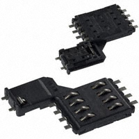


 工商网监
湘ICP备2023018690号
工商网监
湘ICP备2023018690号
