PHASE CHANGE
Heat Pipe Selection Guide ............................................ 126–131
Vapor Chamber Design Guide ........................................ 132–137
Fluid Phase Change applications, often referred to as “re-circulating,” use closed loop
heat pipes to transfer heat quickly through evaporation and condensation within
the heat pipe. Because of their high thermal efficiency, heat pipes are often designed
into advanced heat sink technologies when increased thermal density or physical size
restrictions exist. This similar process is utilized in vapor chamber technology as well.
PHASE CHANGE
124
125
�PHASE
CHANGE
PHASE
CHANGE
HEAT PIPE SELECTION GUIDE
WHY USE HEAT PIPES?
HEAT PIPE INTRODUCTION
Heat pipes are used to transport heat over a distance with very low thermal resistance. This
is very helpful when small or distant heat sources need to be dissipated over a larger area or
moved to a remote heat exchanger. Heat pipes are a Fluid Phase Change application, often
referred to as “re-circulating,” because they use a closed loop to transfer heat quickly through
evaporation and condensation within the heat pipe.
Heat pipes have proven to be robust and reliable over many years in these types of applications. The next section will give
more technical detail on the performance of heat pipes depending on diameter, length, and angle of use. Many thermal
systems benefit from the addition of heat pipes, especially when heat sources are dense and/or remote to the final heat
exchanger. Computer applications, such as processors, graphics cards and other chip-sets, have high thermally dissipated
power in a small area. Fan heat sink combinations used in these applications can offer high-performance dissipation to the
ambient, but much of the battle is to bring the heat to the heat exchanger with as little temperature change as possible. Heat
pipes excel at this and can transport large heat loads from small areas with very little temperature difference.
Heat pipes do not actually dissipate the heat to the environment, but serve to
move heat efficiently within a thermal system. A heat pipe is a copper tube with an
internal wick structure that is sealed on both ends with a small amount of water
inside. As heat is applied to the pipe, the water will boil and turn to a gas, which
then travels to the colder section of the heat pipe where it condenses back to a
liquid. It is the evaporating and condensing of the water that form a pumping action
to move the water (and thus the heat) from end to end of the pipe. There are many
types of wick structure that can be used within the heat pipe and they are generally
classified into grooved, mesh, powder and hybrid.
Heat pipes are used in many harsh environments such as:
•
•
•
•
Telecommunications
Aerospace
Transportation
Computers and Data Centers
KEY FEATURES
•
•
•
•
Material: Copper
Wick Structure: Powder Sintered Copper
Light Weight
Versatile with high thermal performance
HOW HEAT PIPES OPERATE
A grooved heat pipe is a copper tube with a series of shallow grooves around
the internal perimeter of the heat pipe. While the water is a liquid, it travels in the
grooves and while it is a vapor it travels in the open space of the pipe. Grooved
pipes can be used in horizontal orientations, but are very limited in performance if
used above 15° out of horizontal.
GROOVED HEAT PIPE
1
A mesh heat pipe is a smooth wall copper tube with a woven copper mesh
installed along the interior of the pipe. The mesh is designed to remain in
contact with the walls of the pipe in areas where the pipe may be bent or
flattened. Mesh pipes can be used in horizontal and orientations up to 30°
out of horizontal.
3
2
5
4
Heat Source
MESH HEAT PIPE
1.
2.
3.
4.
5.
6.
A powder wick heat pipe can also be known as a sintered heat pipe. During the
manufacturing process a mandrel is installed in the center of the pipe and copper
powder is poured into the pipe around the mandrel. After the powder is sufficiently
packed, the parts are placed into a sintering oven. Once at temperature, the copper
powder will stick to the pipe and to itself, forming numerous internal pockets like a
sponge. Because of the small pocket sizes, sintered pipes can efficiently move the water
and can be used horizontally, vertically and all points in between including upside down.
Working fluid absorbs heat while evaporating to vapor
Vapor transfers along the cavity to the lower temperature area
Vapor condenses back to fluid, discharging heat
Fluid is absorbed by the sintered/powdered wick structure
Fluid returns to high temperature end via capillary force in the wick structure
Natural or forced convection air flow dissipates excess heat to ambient
6
POWDER WICK
HEAT PIPE
126
Wakefield-Vette primarily sells sintered, or powder, style heat pipes due to their higher performance
and the best heat pipe for your application.
127
�PHASE
CHANGE
PHASE
CHANGE
HEAT PIPE SELECTION GUIDE
FLATTENING HEAT PIPES
HEAT PIPE BASICS
When selecting the diameter and length of heat pipe it is important to consider the
orientation with respect to gravity and overall heat load for the thermal system. The
transport of vapor within the heat pipe is responsible for the thermal conduction from
one end to the other. A larger diameter heat pipe can transport more vapor, translating
into a larger heat carrying capacity. Also, the orientation of the pipe with respect to
gravity plays a role in the thermal capacity of a heat pipe.
HEAT PIPE BASICS
•
•
•
•
•
Picking the correct pipe
Transport
General parameters
Bending
Flattening
When selecting the diameter and length of heat pipe it is important to consider the
orientation with respect to The thermal capacity is increased when the heat source is
lower than the condenser (or ambient heat exchanger) because gravity assists the return
of condensed water back to the heat source. The opposite is also true as the thermal
capacity is reduced when the condensed water must move by capillary forces back to the
heat source against gravity. This effect is exaggerated with longer heat pipes and testing
has shown that the gravity effect can nearly the double the thermal capacity in the
advantageous direction and cut the capacity in half in the deleterious direction from the
heat pipe in the horizontal orientation. In the short heat pipe extreme (3”-4” length), this
effect is nearly zero, so please consult with Wakefield-Vette engineers to find the right
solution for your application.
MAXIMUM HEAT TRANSFER TABLE
(POWDER TYPE)
Qmax
Out Diameter
Type
Ф3mm
Flatten
13.2 W
t=2.0mm
Flatten
13.2 W
t=2.5mm
Flatten
13.1 W
t=3.0mm
Round Pipe
13.2 W
HEAT PIPE LENGTH = 150MM
Out Diameter Out Diameter
Ф4mm Ф5mm
16.6 W
20.5 W
19.8 W
23.6 W
34.0 W
51.5 W
19.8 W
28.4 W
39.2 W
67.5 W
19.8 W
30.1 W
48.1 W
74.2 W
MAXIMUM HEAT TRANSFER TABLE
(POWDER TYPE)
Qmax
Out Diameter
Type
Ф3mm
Flatten
7.2 W
t=2.0mm
Flatten
8.1 W
t=2.5mm
Flatten
8.2 W
t=3.0mm
Round Pipe
9.0 W
Out Diameter Out Diameter
Ф6mm Ф8mm
SIZE OF FLATTED HEAT PIPES
Diameter
(mm)
4mm
5mm
6mm
8mm
Thickness
(mm)
3
2.5
2
3.5
3
2
4
3.5
6
5
4
3
Width
(mm)
4.65
5
5.23
5.97
6.25
6.83
7.3
7.58
9.35
9.95
10.5
10.99
Tolerance
(mm)
+/- 0.15
+/- 0.15
+/- 0.15
+/- 0.15
+/- 0.15
+/- 0.15
+/- 0.15
+/- 0.15
+/- 0.15
+/- 0.15
+/- 0.15
+/- 0.15
Bending radius for heat pipes of different
diameters depending on the method of bending.
BENDING
By Hand:
• 4mm: 4 x diameter
• 6mm: 4 x diameter
• 8mm: 5 x diameter
Tooling:
• 4mm: 3 x diameter
• 6mm: 3 x diameter
• 8mm: 4 x diameter
HEAT PIPE LENGTH = 250MM
Out Diameter Out Diameter
Ф4mm Ф5mm
10.1 W
12.2 W
Out Diameter Out Diameter
Ф6mm Ф8mm
11.2 W
13.1 W
16.5 W
23.0 W
12.1 W
14.1 W
22.0 W
37.0 W
12.3 W
15.6 W
29.3 W
45.0 W
wakefield-vette.com
128
Flattening is another aspect of heat pipes that effect their performance. Often it is necessary to
flatten a heat pipe to fit into a desired shape or gap or to increase the contact area of the pipe with
the heat. Since flattening reduces the effective cross-sectional area of the round pipe, the thermal
capacity is reduced, just as if a smaller diameter pipe was being used. The larger diameter of the
starting heat pipe, the larger reduction of thermal capacity is seen when flattening. Also, the larger
diameter pipes cannot be flattened to the same ultimate dimension as the smaller pipes without
disrupting heat flow altogether. This is also true for bending of pipes. The radius of bending is usually
3-5x the diameter of the heat pipe depending on the pipe diameter and the process of bending the
pipe. The potential danger is to collapse the pipe, effectively cutting off vapor and thermal transport.
Contact us: (603) 635-2800
129
�PHASE
CHANGE
PHASE
CHANGE
HEAT PIPE SELECTION GUIDE
HEAT PIPE ASSEMBLIES
WAKEFIELD-VETTE STANDARD HEAT PIPES
Interfacing heat pipes with plates and heat exchangers is predominately about maximizing contact
area while adhering to the flattening and bending guidelines mentioned above. In most cases, the
heat pipes are slotted into channels/grooves in the plate to maximize contact. The heat pipe can
be secured into the groove using solder or thermal epoxy, which also augments the contact area
of the heat pipe. The heat pipe can also be clamped between two plates with matching channels/
grooves which are fastened together. In the clamped configuration, thermal grease can be used to
increase the contact of the heat pipe to the plates to reduce the thermal resistance of the contact
interface, just as the thermal epoxy and solder did in the prior example.
Vapor transports heat from evaporator to
condenser. Condensed liquid flows back to
evaporator through capillary action.
Heat pipe dissipates thermal power to
fins/ heat exchanger and condenses
vapor to liquid.
Wakefield-Vette offers individual Heat Pipes through distribution. These most common offerings are a great option for
testing, sampling, and validating your heat pipe solution into eventual production.
When building or testing your heat sink assembly please feel free to contact one of Wakefield Vette’s authorized distributors
to purchase. Always remember to contact us for free consultation on assembly design or parameter questions.
Wakefield-Vette
Part Number
121686
121687
121688
110578
110579
110580
110581
110582
121968
110583
110584
110585
121689
121690
121691
121692
121716
121717
121718
121719
121720
121721
121722
121723
121724
121725
121726
121727
121728
121729
120231
120229
Description
Round Heat Pipe 4 x 70mm
Round Heat Pipe 4 x 100mm
Round Heat Pipe 4 x 150mm
Round Heat Pipe 6 x 100mm
Round Heat Pipe 6 x 150mm
Round Heat Pipe 6 x 200mm
Round Heat Pipe 6 x 250mm
Round Heat Pipe 6 x 300mm
Round Heat Pipe 8 x 100mm
Round Heat Pipe 8 x 200mm
Round Heat Pipe 8 x 250mm
Round Heat Pipe 8 x 300mm
Round Heat Pipe 10 x 100mm
Round Heat Pipe 10 x 200mm
Round Heat Pipe 10 x 250mm
Round Heat Pipe 10 x 300mm
Flat Heat Pipe 2.5 x 100mm
Flat Heat Pipe 2.5 x 150mm
Flat Heat Pipe 2.5 x 200mm
Flat Heat Pipe 2.5 x 250mm
Flat Heat Pipe 3 x 100 mm
Flat Heat Pipe 3 x 150 mm
Flat Heat Pipe 3 x 200 mm
Flat Heat Pipe 3 x 250 mm
Flat Heat Pipe 3 x 300 mm
Flat Heat Pipe 4.5 x 100mm
Flat Heat Pipe 4.5 x 150 mm
Flat Heat Pipe 4.5 x 200 mm
Flat Heat Pipe 4.5 x 250 mm
Flat Heat Pipe 4.5 x 300 mm
Ultra Thin 6MM DIA X 1.50MM
Ultra Thin 5MM DIA X 1.00MM
Embedded heat pipe in plate absorbs heat
through vaporization of liquid.
wakefield-vette.com
130
Contact us: (603) 635-2800
131
�PHASE
CHANGE
PHASE
CHANGE
VAPOR CHAMBER DESIGN GUIDE
WHY USE VAPOR CHAMBERS?
VAPOR CHAMBER INTRODUCTION
Vapor Chambers are used to transport heat over a distance with very low thermal resistance.
This is very helpful when small heat sources need to be dissipated over a larger area. Vapor
chambers are a Fluid Phase Change application because they use a closed loop to transfer heat
quickly through evaporation and condensation within the chamber. The particular aspect useful
in designs is that vapor chambers transport heat in a plane, more effectively “spreading heat”
compared to a heat pipe which transports heat over a distance in a straight line.
Vapor chambers, like heat pipes, do not actually dissipate the heat to the
environment, but serve to move heat efficiently within a thermal system. A
vapor chamber is made from copper plates (top and bottom) with an internal
wick structure that is sealed around the perimeter with a small amount of water
inside. As heat is applied to the chamber, the water will boil and turn to a gas,
which then travels to the colder section of the vapor chamber, where heat is
dissipated through an external heat exchanger, where it condenses back to a
liquid. It is the evaporating and condensing of the water that form a pumping
action to move the water (and thus the heat) from the area of the heat source
to all other areas of the vapor chamber.
There are a few types of wick structure that can be used within the vapor chamber, but
most commercial chambers are classified as mesh or powder. In both cases, the powder
or mess line the copper plate surfaces to allow water flow to/from all directions within
the area of the vapor chamber. Often, when mesh is used as the wick structure, different
sized meshes are used together to promote condensation or transport of liquid depending
on the void size. Vapor chambers are best used in horizontal orientations. The effects of
gravity may vary depending on application and orientation, but one must consider lower
performance if used above 15° out of horizontal.
TOP COPPER PLATE
TOP WICK
(COPPER MESH)
COPPER COLUMNS
WORKING FLUID
BOTTOM WICK
(COPPER MESH)
BOTTOM COPPER PLATE
wakefield-vette.com
132
During the manufacturing process copper columns
are used throughout the vapor chamber to
support the plates that act as the lids and contain
the liquid and vapor. The copper mesh is oriented
within the chamber pressed against the copper
plates. The plates are sealed around the perimeter
via diffusion bonding. In some cases, soldering or
welding are used, but diffusion bonding allows for
the strongest and highest temperature compatible
seal for the vapor chamber. The diffusion bonding
process also allows the mesh to bond to the
copper plates as well.
Vapor chambers have proven to be robust and reliable over many years in these types of applications. The next section will
give more technical detail on the performance of vapor chambers depending on thickness and area. Many thermal systems
benefit from the addition of vapor chambers, especially when heat sources are dense and the final heat exchanger is much
larger and the heat from the source must be spread to a larger area effectively to efficiently use the heat exchanger. Computer
applications, such as processors, graphics cards and other chip-sets, have high thermally dissipated power in a small area. Fan
heat sink combinations used in these applications can offer high-performance dissipation to the ambient, but much of the battle
is to spread the heat to the heat exchanger with as little temperature change as possible. Vapor chambers excel at this and can
transport large heat loads from small areas with very little temperature difference.
Vapor chambers are used in many harsh environments such as:
• Computers and Data Centers
• Telecommunications
• Aerospace
• Transportation
KEY FEATURES
•
•
•
•
Material: Copper
Wick Structure: Copper Mesh
Light Weight
Versatile with high thermal performance
HOW VAPOR CHAMBERS OPERATE
COOLING
HEAT EXCHANGER
FINS
VAPOR CHAMBER
HEAT SOURCE
COPPER COLUMN
MESH
WICK
Contact us: (603) 635-2800
133
�PHASE
CHANGE
PHASE
CHANGE
VAPOR CHAMBER DESIGN GUIDE
VAPOR CHAMBERS THERMAL CAPACITY
VAPOR CHAMBER BASICS
VAPOR CHAMBER BASICS
When considering the use of a vapor chamber in your application, it is important to consider the
orientation with respect to gravity and overall heat load for the thermal system. The transport of
vapor within the vapor chamber is responsible for the thermal conduction from one area to the
other. A thicker vapor chamber can transport more vapor, translating into a larger heat carrying
capacity. Although vapor chambers can have complex shapes and mounting features, they are not
typically bent and integration can be more direct with the heat source than with heat pipes.
• Comparison to Heat Pipes
• Transport
• General parameters
VAPOR CHAMBER
HEAT PIPE
Theory
2-Phase heat transfer
2-D heat distribution. Spreading heat by a single vapor
chamber. Suitable for large heat flux and high power.
Complex shape in X and Y direction with pedestal.
Mounted with through-holes in vapor chamber
Direct contact. Mounting pressure to 90PSI
T=5mm > 400W; T=3mm > 200W; T=1mm > 60W
Vapor chamber has larger tooling cost so high volume
applications can lower cost to ~2X heat pipe. However,
solution may need only 1 vapor chamber compared to
many heat pipes and fixture/base plates.
Much like heat pipes, the ultimate dimension in determining heat carrying capacity of a vapor
chamber is the volume of the vapor space. This is determined by the thickness and area of the
vapor chamber. For most applications, the thickness of the vapor chamber does not exceed 3mm,
however pedestals and other surface features can be used to contact specific heat sources while
leaving clearance for other board mounted objects. These pedestals can be extended 5mm from
the vapor chamber lid plate. Mounting holes can also be integrated within the area of the vapor
chamber for better integration with the heat source and locating the heat source a the center of
the vapor chamber with good pressure application.
Application
Shape
Fixtures
Heat Source Contact
Qmax
Cost
2-Phase heat Transfer
1-D heat distribution. Using one or more heat pipes to spread heat.
Suitable for long distance between heat source and heat exchanger.
HEAT CARRYING CAPACITY (Q-MAX) BY VAPOR CHAMBER THICKNESS
Round, flattened or bent in any direction.
Additional fixure plates needed to mount heat pipes.
A base plate required to contact the heat source unless
flattened/machined.
Ø5 > 20W; Ø6 > 40W; Ø8 > 60W
Lower cost for a single heat pipe, but may also need tooling cost for
bending/flattening.
�
45*45
90*90
120*120
150*150
200*200
250*250
300*300
1.0mm
10W
40W
40W
1.2mm
15W
50W
50W
1.5mm 2.0mm 2.3mm 2.5mm 3.0mm >3.0mm
20W
25W
60W
80W
100W
>100W
80W
100W
150W
180W
250W
>300W
80W
100W
160W
200W
275W
>300W
80W
100W
170W
220W
300W
>300W
100W
175W
225W
>300W
>300W
180W
240W
>300W
>300W
>300W
Note: Heat source = 30*30mm
This table is for reference. Q-max is related to heat source power density and effectiveness of final
heat exchanger.
In many applications, the decision to use a vapor chamber is frequently compared to a thermal
solution using heat pipes. In both cases, 2-phase transport is used as a vapor moves heat within
the chamber or pipe and the liquid is condensed at the heat exchanger and transported back
to the heat source. However, the main aspects of applications that differentiate vapor chambers
from heat pipes are:
•
•
High power density: when the heat source is small but heat generation is large, vapor
chambers can more easily transport the heat to a larger area. A heat pipe solution would
require multiple pipes, which may be difficult to integrate within the footprint of the heat source.
High power: when the application must dissipate large wattage, a vapor chamber spreads the
heat to a large area efficiently with similar temperatures of the chamber surface. This allows
more efficient use of the final heat exchanger since hot spots are minimized. Heat pipes
can also spread the heat, but unless many are ganged together, the hot spots may still persist.
wakefield-vette.com
134
Contact us: (603) 635-2800
135
�PHASE
CHANGE
PHASE
CHANGE
VAPOR CHAMBER DESIGN GUIDE
WAKEFIELD-VETTE STANDARD VAPOR CHAMBERS
VAPOR CHAMBER ASSEMBLIES
Interfacing vapor chambers with plates and heat exchangers is predominately about maximizing contact
area. In most cases, the vapor chambers are soldered to heat exchanger fins for air cooled applications.
The vapor chambers can also be soldered to liquid cold plates to take advantage of spreading the heat
before final heat exchange with the liquid. In many cases, the vapor chambers are also integrated with
heat pipes to take the heat that has spread in the plane of the vapor chamber and extend it in the vertical
dimension to more efficiency interact with cooling fins. Integrating with the heat source is most commonly
done with pressure, up to 90 psi, and the use of a thermal grease or other interface material to maximize
surface area contact to the source.
Wakefield-Vette offers individual vapor chambers through distribution. These most common offerings are a great option for testing,
sampling, and validating your vapor chamber solution into eventual production. When building or testing your heat sink assembly
please feel free to contact one of Wakefield-Vette’s authorized distributors to purchase. Always remember to contact us for free
consultation on assembly design or parameter questions.
WKV Part #
VC-1131-8175-517
VC-90-90-3
VC-106-70-3
VC-106-82-3
Product Description
Thermal Resistance Length Width Thickness qMax
Standard Vapor Chamber 113.1mm x 81.75mm X 5.17mm
0.145
113.1
81.75
5.7
180W~
Standard Vapor Chamber 90mm x 90mm x 3.00mm
0.143
90
90
3
150W~
Standard Vapor Chamber 106mm x70mm x 3mm
0.150
106
70
3
150W~
Standard Vapor Chamber 106mm x 82mm x 3mm
0.140
106
82
3
150W~
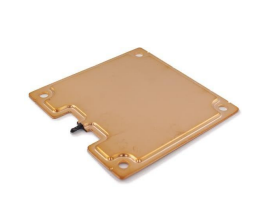
PART NUMBER VC-1131-8175-517
Product Info Description
Dimension(mm): L: 113mm / W: 81.8mm / T: 5.7mm
Operation Power: 180W~
Product Info Details
Thermal Resistance: 0.145°C/W
Operation Temp: 40~130°C
Platform : VGA
PART NUMBER VC-90-90-3
Product Info Description
Dimension(mm): L: 90mm / W: 90mm / T: 3mm
Operation Power: 150W~
PART NUMBER VC-106-70-3
2 TYPES OF FILLING PORTS
(7MM MAXIMUM):
RETRACTED
Product Info Details
Thermal Resistance: 0.143°C/W
Operation Temp: 40~140°C
Platform : Intel 2011 Square
CHAMFER
Product Info Description
Dimension(mm): L: 106mm / W: 70mm / T: 3mm
Operation Power: 150W~
Product Info Details
Thermal Resistance: 0.150°C/W
Operation Temp: 40~140°C
Platform : Intel 2011 Narrow
PART NUMBER VC-106-82-3
Product Info Description
Dimension(mm): L: 106mm / W: 82mm / T: 3mm
Operation Power: 150W~
wakefield-vette.com
136
Product Info Details
Thermal Resistance: 0.140°C/W
Operation Temp: 40~140°C
Platform : Intel 2011 Narrow
Contact us: (603) 635-2800
137
�


 工商网监
湘ICP备2023018690号
工商网监
湘ICP备2023018690号
